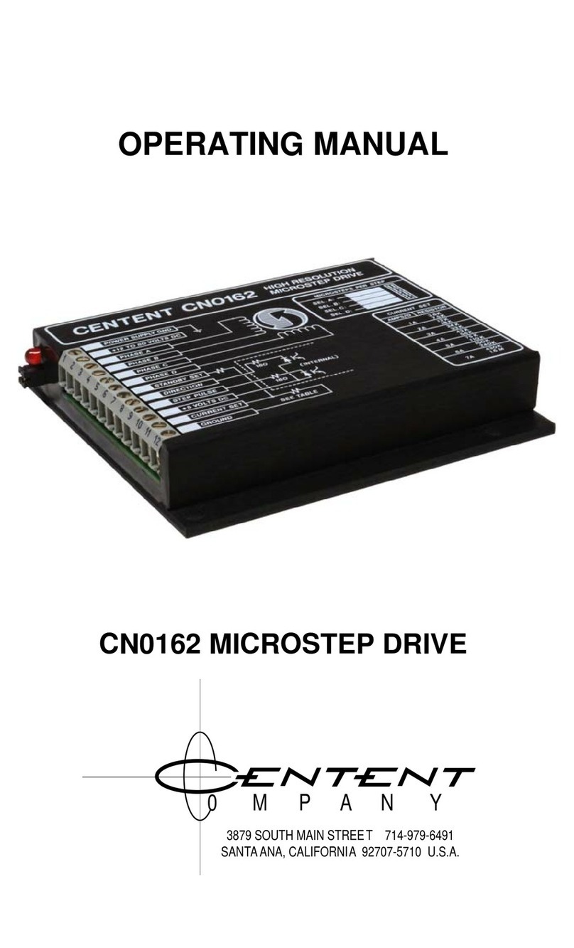
CENTENT CN0165 User manual

CN0165
OPERATING MANUAL
HIGH RESOLUTION MICROSTEP DRIVE
3879 SOUTH MAIN STREET 714-979-6491
SANTAANA, CALIFORNIA 92707-5710 U.S.A.
0 M P A N Y

This manual contains information for installing and operating the following
Centent Company product:
CN0165 Microstep Drive
Centent and the Centent Company logo are trademarks of Centent Company.
Other trademarks, tradenames, and service marks owned or registered by any other
company and used in this manual are the property of their respective companies.
Copyright ©2019 Centent Company
3879 South Main Street
Santa Ana, CA 97207
All Rights Reserved

GENERAL DESCRIPTION...............................................................................1
LOCATION OF COMPONENTS......................................................................2
INSTALLATION
Heat Sinking .................................................................................................3
Power Supply................................................................................................4
Motor lead color codes................................................................................. 8
Fault/Reset....................................................................................................9
Direction.....................................................................................................10
Step Pulse ...................................................................................................10
+5 VDC ......................................................................................................10
Current Set..................................................................................................11
Current Set Table........................................................................................13
Option Header............................................................................................ 14
OPERATION
Standby Current Trimpot............................................................................ 15
Offset Trimpot.............................................................................................15
Fault Led ....................................................................................................16
Power-On Reset.......................................................................................... 16
Under-Voltage Lockout ..............................................................................16
PERFORMANCE
Microstepping............................................................................................. 16
Anti-resonance............................................................................................17
Torque and Power......................................................................................18
Motor Winding Configuration....................................................................19
Power Supply Voltage ................................................................................22
Power Supply Current................................................................................22
Motor and Drive Heating ...........................................................................23
ACCURACY
Motor Tolerances .......................................................................................23
Motor Load.................................................................................................24
Motor Linearity...........................................................................................24
Current Profile Option ...............................................................................25
SPEED-TORQUE CURVES............................................................................25
FULL SCALE DRAWING ...............................................................................40
SPECIFICATIONS ..........................................................................................41
INDEX...............................................................................................................42


1
GENERAL DESCRIPTION
The Centent CN0165 is a high resolution step motor drive designed for the operation of
hybrid PM step motors rated from 0.1 to 20 amps per phase. The CN0165 operates on a
supply voltage of 18-80 volts DC. Drive output current ranges from 0.1 to 10 amps per
phase. Maximum step input frequency is 1.5 MHz. The minimum on or off time for the
step input is 300 nanoseconds. Motor winding inductance as low as 0.5 millihenrys is
permitted.
The CN0165 features eight selectable microstep resolutions per drive. Available
resolutions range from full-step to 256 microsteps per full step. The step resolution is
selected by jumpering the option header located on the face of the drive.
The CN0165 is capable of delivering up to 1.5 million microsteps per second to the step
motor. The pin-out of the CN0165 is compatible with other Centent step motor drives.
The design of the CN0165 is a combination of recirculating current and non-recirculating
current type chopper drives. It features electronic viscous damping for control of motor
mid-band instability (anti--resonance) and a high-speed torque boost circuit. MOSFET
transistors are utilized in the 'H' bridge output circuit. Automatic current standby, easily
adjustable from zero to full current, reduces motor phase current while the motor is at
rest. The combination of these features results in an extremely efficient step motor drive
with minimum motor iron losses (heating).
The CN0165 uses high speed opto-isolators for the Step Pulse and the Direction inputs to
provide maximum noise immunity. The Step Pulse and Direction inputs are compatible
with TTL drivers and require no additional components.
Motor stepping occurs on the high to low transition of the Step Pulse Input. The
Direction Input hold time is one microsecond after the active edge of the Step Pulse
Input. The Direction Input can be updated simultaneously with the active transition of the
Step Pulse Input.
Over-current conditions like winding shorts, overheating conditions such as insufficient
heat sinking, and under-voltage conditions like power supply failure are sensed by the
CN0165. When any of these conditions occur the CN0165 shuts down, activating the
Fault Output and lighting the Fault LED located on the face of the drive.
The Centent CN0165 High Resolution Microstep Drive is compact; measuring 4.75
inches x 4.00 inches x 0.85 inches (121mm x 102mm x 22mm). It comes encapsulated in
a heat conductive epoxy and encased in an anodized aluminum cover. This results in a
rugged package that resists abuse and contamination, suitable for harsh environments.

CENTENT CN0165 MICROSTEP DRIVE
2
LOCATION OF COMPONENTS
(1) MOUNTING PLATE
The base plate also serves as a heat sink, although additional heat sinking may be
required. The temperature of the drive must never exceed +70°C (+158°F). Four
mounting holes on 3.625 inch (92 mm) centers are provided to secure the drive to the
heat sink or the user’s equipment.
(2) OPTION HEADER
A six pin header selects the active
microstep resolution or current profile.
The user jumpers the desired pins with the
shorting bars supplied with the drive.
Eight resolutions or current profiles are
available in each drive. The value for each
selection is printed in the Resolution
Table (see Page X14X). There are 21
microstep resolutions available for the
CN0165 Microstep Drive.
Figure 1 - Component location
(3) FAULT LED
This light emitting diode turns on when the CN0165 is in a fault mode. The fault status is
also available on the Fault/Reset Terminal of the connector (see page X9X). A fault
condition is cleared by shorting the Fault/Reset Terminal to ground potential or by
recycling the power supply (power off, power on).
(4) TERMINAL CONNECTOR
A 12 position terminal strip provides the connections for the power supply, the motor, the
Current Set and the indexer interface (Step Pulse and Direction inputs). Care must be
taken not to over-torque the terminal screws to prevent damage to the connector.
(5) RESOLUTION TABLE
The Resolution Table provides a diagram of each Option Header configuration, and the
resolution associated with it. A maximum of eight of the twenty-one possible step
resolutions are available in each CN0165.
(6) CURRENT SET TABLE
This table provides the user with standard 5% values for the Current Set Resistor
connected between terminals 11 and 12 of the Terminal Connector.Values are given for
Parallel and Series operation from 0.25 to 20 amps per phase.
(7) OFFSET TRIMPOT
This is a fine-tuning adjustment for high microstep resolutions. It is used to optimize
operation at resolutions of sixteen microsteps or greater.
(8) STANDBY TRIMPOT
This trimpot sets the current level of the CN0165 during periods of motor inactivity.
Standby current may be set from 0% to 100% of operating current.
13
24
76
8
5

INSTALLATION
3
SECURING AND WIRING THE DRIVE
The mounting holes in the corners of the drive provide the means of mounting the drive
to the system chassis or bulkhead. It is desirable to mount the drive close to the motor
and to make the motor phase wiring as short as possible. This will help to minimize
noise generated from this source. Although the drive is impervious to dirt and grease,
the connector must be protected from contamination.
A major factor in choosing the mounting location is heat sinking. An aluminum chassis
will extract heat from the drive while a steel one will not. Dirty or painted surfaces are
poor heat conductors. Clean the mating surfaces between drive and chassis before
assembly. Use of a commercial transistor heat sink compound enhances the dissipation
of heat from the CN0165 drive.
The protection provided by the internal temperature sensor of the CN0165 is not
designed as a substitute for adequate heat sinking. Repeatedly tripping the Fault Output
by allowing the drive to overheat causes thermal stress that will eventually lead to
permanent damage.
If this occurs it will be necessary to provide additional heat sinking. As a practical
guide, additional heat sinking will be necessary for the CN0165 if it is operated at three
amps or more. A fan to force air circulation through the heat sink may also be required.
The optional HSK heat sink kit for Centent drives consists of heat sink, side rails and
screws to secure the drive and side rails. The side rails are reversible, allowing the two
mounting configurations shown in XFigure 2X. Contact Centent Company to order the
HSK heat sink kit.
Figure 2 - HSK heat sink kit
No additional connectors are required when wiring to the Terminal Connector of the
CN0165. Either stranded or solid conductor wire may be used. A wire size of 16-22
gauge is recommended. The insulation should be stripped back 0.25 inches (7 mm) for
insertion into the terminal block. Care must be taken when tightening the screws in the
terminal block. Use a torque limiting driver if possible, to avoid damage to the
terminals.
CAUTION: DO NOT OVER-TORQUE THE TERMINAL CONNECTOR
SCREWS. MAXIMUM TORQUE ON THE TERMINALS IS 4.5 LB. - IN.

CENTENT CN0165 MICROSTEP DRIVE
4
POWER SUPPLY INPUTS
Terminal 2 connects to the positive output from the power supply. The voltage range is
+18 to +80 VDC. The power supply may be unregulated. Limit the ripple voltage
(unregulated supplies) to a maximum of 10% of the DC output voltage. Terminal 1 is
the ground connection. Do not use Terminal 12 for power supply ground; it is the return
connection for the Current Set resistor.
For those users that wish to build their own power supply, XFigure 3Xshows a suggested
circuit. Because of the electrical noise generated by these drives, it is not recommended
that the supply be shared with low level logic circuitry.
Figure 3 - Power Supply
The power supply terminals should have a capacitor of 470µf or greater
connected across them. This is particularly important for regulated power
supplies since they usually have little output capacitance. Locate the
capacitor as close to Terminals 1 & 2 of the CN0165 as possible (see
XFigure 3X, C2). Be sure the voltage rating for the capacitor is higher than
the drive’s supply voltage.
During rapid deceleration of large inertial loads from high speeds, step motors become
generators of considerable electrical power. This is returned to the power supply by the
step motor drive. If the supply cannot absorb this power, the voltage generated may
exceed the 80 volt limit of the CN0165, thus damaging the drive and power supply.
To protect the drive and power supply, the user may connect an external zener diode
from Terminal 2 to ground (see XFigure 3X, D5). This diode will protect the drive from
over-voltage conditions. Recommended diodes are 1N4762 (one watt) or 1N5375 (five
watt). Note the 7-10 amp fuse (F1) placed in series with Terminal 2 and the power
supply. Be sure this fuse is located between the power supply and the zener diode. In
case of an over-voltage condition, the zener diode and fuse may be destroyed, but the
CN0165 and the power supply will be protected from damage.
The power supply current required depends on the motor being used and whether the
configuration is for parallel or series operation. See Motor Winding Configuration in
the Performance section of this manual on page X19Xfor a complete explanation of motor
wiring options.

INSTALLATION
5
Parallel operation requires a maximum of
two thirds of the motor's rated per phase
current.
Series operation requires a maximum of one
third the motor's rated per phase current.
Use the manufacturer's phase current rating for the motor and the motor wiring
configuration (high or low performance) to estimate the size of power supply required.
As an example, a six lead motor rated by the manufacturer at four amps per phase is
connected in the full winding (series) configuration. To calculate the current required
from the power supply use Equation 2. Assume a transformer with a 25 volt RMS
secondary is used. After rectification the transformer will produce a 37 VDC power
supply voltage. To calculate the size of the filter capacitor (C1) use the following
equation:
()()
(
)
(
)
ff
VI
CSUPPLY
SUPPLY
μμ
300048.2995
37 33.1333,83333,83
1≈===
Equation 3 - Power Supply filter capacitor
C2 (XFigure 3X, page X4X) is the 470 µf capacitor located close to the CN0165’s power
supply terminals. C1may be made smaller by that amount if desired. Both capacitors
must have a voltage rating safely in excess of the power supply voltage, 50 VDC in this
example.
More than one CN0165 may be run from a common power supply if the filter capacitor
is large enough to handle the combined load of the drives. Each CN0165 must have
separate power leads to the supply. Do not daisy-chain power leads from supply to
driver to driver.
ISUPPLY = 2/3 x IPHASE
Equation 1 - Drive Current (Parallel)
ISUPPLY = 1/3 x IPHASE
Equation 2 - Drive Current (Series)

CENTENT CN0165 MICROSTEP DRIVE
6
MOTOR PHASE OUTPUTS
These are the drive’s
outputs to the step motor
phase windings. One motor
winding pair goes to
Terminals 3 & 4 and the
other motor winding pair
goes to Terminals 5 & 6.
The CN0165 is designed to drive four, six and eight lead step motors. With six or eight
lead motors, there are two options for connecting the motor to the drive. They are Series
and Parallel, as shown in XFigure 4Xand XFigure 5X.
Figure 4 - Parallel configuration
Figure 5 - Series configuration
Since a four lead motor has only one possible wiring configuration, consider it to be
connected in the Parallel configuration. See Motor Winding Configuration in the
Performance section of this manual (page X19X) to determine the best wiring configuration
for the application.
The CN0165 is a high frequency switching type drive. Because of the rapid rate of
voltage and current change inherent with this type of drive, considerable RFI is
generated. The following precautions will prevent noise from coupling back to the
inputs and causing erratic operation.
n.c.
n.c.
6 LEAD
MOTOR
PHASE A
PHASE C
PHASE B
PHASE D
8 LEAD
MOTOR
PHASE A
PHASE C
PHASE B
PHASE D
n.c.
n.c.
6 LEAD
MOTOR
PHASE A
PHASE C
PHASE B
PHASE D
8 LEAD
MOTOR
PHASE A
PHASE C
PHASE B
PHASE D

INSTALLATION
7
The Parallel configuration in a six lead motor uses the center-tap and one end to form a
winding. The other lead of each phase pair is not connected. For an eight lead motor,
the phases are connected as two pairs of parallel windings. See
Figure 4Xfor details.
The Series configuration in a six lead motor uses the end leads of each phase to
constitute a winding. The center-taps are not used. For an eight lead motor the phases
are connected as a pair of series windings. See Figure 5 for details.
1. Never run the motor leads in the same cable or wiring harness as
the Step Pulse, Direction or +5 VDC input lines.
2. Keep power supply leads as short as possible. If the length exceeds
12 inches, use a 0.1 µf capacitor across Terminals 1 & 2 at the
drive.
3. Never wire capacitors, inductors or any other components to the
motor output terminals.
4. Ground the CN0165 case.
5. Ground the step motor case.
Tables 1 & 2, page X8X, show various manufacturers’ color codes for six lead motors and
the connections to the CN0165 for half winding and full winding operation. Tables 3 &
4 show how to connect various manufacturers’ eight lead motors for series and parallel
operation.
Note that the leads connected together for series operation do not connect to a terminal
on the CN0165. These leads should not be left exposed; insulate them with electrical
tape or heat-shrink tubing.
Consult the motor manufacturer's catalog for motors not listed in tables 1 through 4.

CENTENT CN0165 MICROSTEP DRIVE
8
CN0165 TERMINAL
MANUFACTURER 3 4 5 6
SUPERIOR ELECTRIC GREEN/WHITE GREEN RED/WHITE RED
RAPIDSYN GREEN/WHITE GREEN RED/WHITE RED
IMC GREEN/WHITE GREEN RED/WHITE RED
EASTERN AIR DEV. GREEN/WHITE GREEN RED/WHITE RED
PACIFIC SCIENTIFIC BLACK ORANGE RED YELLOW
WARNER ELECTRIC BROWN ORANGE RED YELLOW
VEXTA BLUE RED BLACK GREEN
JAPAN SERVO BLUE RED YELLOW GREEN
Table 1 - Full Winding Operation
CN0165 TERMINAL
MANUFACTURER 3 4 5 6
SUPERIOR ELECTRIC WHITE GREEN BLACK RED
RAPIDSYN WHITE GREEN BLACK RED
IMC WHITE GREEN BLACK RED
EASTERN AIR DEV. WHITE GREEN BLACK RED
PACIFIC SCIENTIFIC BLACK ORG./BLACK RED RED/YEL.
WARNER ELECTRIC BLACK ORANGE RED WHITE
VEXTA BLUE WHITE YELLOW GREEN
JAPAN SERVO BLUE WHITE•WHITE•GREEN
White leads are NOT interchangeable. Use ohm meter to find White-Blue & White-Green pairs.
Table 2 - Half Winding Operation
CN0165 TERMINAL
MANUFACTURER 3 4 5 6
SUPERIOR RED RED/WHITE GREEN GRN./WHT.
ELECTRIC BLACK ∋WHITE ORANGE ∋BLACK/WHITE
PACIFIC BLACK ORANGE RED YELLOW
SCIENTIFIC BLACK/WHITE ∋ORANGE/WHITE RED/WHITE ∋YEL./WHITE
BODINE BROWN ORANGE RED YELLOW
BRN./WHITE ∋ORANGE/WHITE RED/WHITE ∋YEL./WHITE
PORTESCAP BROWN ORG./WHITE RED YEL./WHITE
BROWN/WHITE ∋ORANGE RED/WHITE ∋YELLOW
DIGITAL MOTOR BLACK ORANGE RED YELLOW
BLACK/WHITE ∋ORANGE/WHITE RED/WHITE ∋YEL./WHITE
Table 3 - Series Winding Operation
CN0165 TERMINAL
MANUFACTURER 3 4 5 6
SUPERIOR
ELECTRIC RED
WHITE BLACK
RED/WHITE GREEN
BLACK/WHITE ORANGE
GRN./WHITE
PACIFIC
SCIENTIFIC BLACK
ORANGE/WHITE BLACK/WHITE
ORANGE RED
YEL./WHITE RED/WHITE
YELLOW
BODINE BROWN
ORG./WHITE BRN./WHITE
ORANGE RED/WHITE
YELLOW RED
YEL./WHITE
PORTESCAP BROWN
ORANGE BRN./WHITE
ORG./WHITE RED
YELLOW RED/WHITE
YEL./WHITE
DIGITAL MOTOR BLACK
ORANGE/WHITE BLACK/WHITE
ORANGE RED
YEL./WHITE RED /WHITE
YELLOW
Table 4 - Parallel Winding Operation

INSTALLATION
9
FAULT / RESET
(INPUT/OUTPUT)
Terminal 7 is the Fault/Reset Terminal. This serves both as an output, to indicate when
a fault has occurred; and as an input, to reset the drive.
The CN0165 has protection circuitry to shut down the drive when potentially damaging
conditions exist. The state of the protection circuitry is available on the Fault/Reset
Terminal. The Fault LED (light emitting diode) provides visual indication of the fault
condition.
The Fault Output latches low and the LED stays on for either of the following fault
conditions:
•A short circuit of the motor windings (or motor lead wiring)
•Overheating: temperature of CN0165 exceeds 70°C
A short circuit reset is distinguished from an overheating reset by observing the case
temperature of the CN0165. A short-circuit reset will shut down the drive before it
reaches a high temperature. If the case temperature is low immediately after a reset
occurs, the cause is a short circuit.
Do not continue to operate the CN0165 if it is resetting due to overheating. Heat sinking
must be provided to prevent the drive from repeatedly entering thermal shutdown.
The Fault Output goes low (LED on), but does not latch, if the power supply voltage
drops below 18 volts DC. When no fault condition exists, the Fault Output is pulled up
to 12 volts DC by an internal 470 ohm resistor and the LED is turned off. The Fault
Output is capable of sinking up to 20 milliamps of current.
While the Fault Output is low, the internal counters reset to microstep zero and the
phase outputs are held low. The CN0165 ceases all switching activity and the motor
phase current goes to zero. A latched fault condition is cleared by a Reset (take
Terminal 7 to ground) or by recycling the power supply to the drive (power off, power
on).
Terminal 7 also functions as a Reset input. By taking the Fault/Reset Terminal to
ground, the motor phase currents are shut off and the internal counters are reset. When
Terminal 7 is released from ground the motor is located at microstep zero. A current of
20 milliamps will flow from the Fault/Reset Terminal when it is shorted to ground.
THE PROTECTION PROVIDED BY THE INTERNAL TEMPERATURE
SENSOR OF THE CN0165 IS NOT A SUBSTITUTE FOR ADEQUATE
HEAT SINKING. REPEATEDLY TRIPPING THE FAULT OUTPUT BY
ALLOWING THE DRIVE TO OVERHEAT CAUSES THERMAL STRESS
THAT WILL EVENTUALLY LEAD TO FAILURE OF THE DRIVE.

CENTENT CN0165 MICROSTEP DRIVE
10
DIRECTION INPUT
Terminal 8 is the Direction Input. This input is sampled by the CN0165 on every step
pulse input to determine which direction the step motor will move.
The state of the Direction Input must be held one microsecond after the active edge of
the Step Pulse Input to insure correct direction. The Direction Input can be updated
simultaneously with the active (high to low) transition of the Step Pulse Input.
The CN0165 uses a high speed opto-isolator for the Direction Input. The purpose of the
opto-isolator is to isolate the Direction Input from the driver's power supply. The user
must provide a +5 VDC supply to operate the opto-isolator. This permits the use of
current sink drivers, such as TTL logic or open collector transistors, to operate the
input. The minimum current required to operate the opto-isolator is 3.5 milliamps.
STEP PULSE INPUT
Microstepping in the CN0165 occurs on the high to low transition of the step pulse
input.
The CN0165 employs a high speed opto-isolator to isolate the Step Pulse Input from the
driver's power supply. The user must provide a +5 VDC supply (shared with the
Direction Input) to operate the opto-isolator circuitry. This permits the use of current
sink drivers, such as TTL logic or open collector transistors, to operate the input.
The minimum current required to operate the opto-isolator is 5 milliamps. The
maximum Step Pulse rate is 1.5 MHz. The minimum on or off time is 50 nanoseconds.
+5 VDC INPUT
This input is connected internally to the anodes of the Step Pulse and the Direction
opto-isolator LEDs. The external +5 VDC supply provides the source of LED current
for the Step Pulse and Direction inputs. A minimum of 10 mA is required (Step and
Direction both 'on' @ 5 mA per opto-isolator).
Power supply voltages higher than 5 VDC may be used for this input. Both the Step
Pulse and the Direction Input will require external resistors to limit the current to the
opto-isolators if the operating voltage is higher than five volts. The following equation
determines the value for these resistors and limits the supply current to the opto-isolator
LEDs to approximately five milliamps.

INSTALLATION
11
01.
)5(
R−
=VEquation 4 - External Opto-isolator resistor
For example, if a +12 volt supply is to be used:
Ω≈=
−
=680007
.01 )5(12
R
Place 680 ohm resistors between Terminal 8 and the Direction source and between
Terminal 9 and the Step Pulse source.
to direction source
to step pulse source
from power source
Figure 6 - External Opto-isolator resistors
IMPORTANT: DO NOT PUT A RESISTOR IN SERIES WITH THE +5 VDC TERMINAL.
CURRENT SET
The Current Set Input determines the magnitude of the motor phase currents. This is
done by connecting a ¼ watt resistor between terminals 11 & 12. Terminal 11 is the
Current Set Input and Terminal 12 is the ground reference.
Table 5, page X13X, lists resistors to the nearest 5% standard value, for both parallel (half
winding) and series (full winding) operation. An abbreviated table is printed on the case
of the CN0165 for user convenience. Use the parallel values for operating four lead
motors.
The resistor values in Table 5 and on the case of the CN0165 are derived by using the
following equation:
SET
SET
SET II
R−
=10 ))(47000(
Where:
R
SET = current set resistor
I
SET = desired current.
Equation 5 - Current Set resistor

CENTENT CN0165 MICROSTEP DRIVE
12
Zero operating current is obtained by shorting terminals 11 & 12 together.
The maximum phase current of 10 amps is obtained with no resistor installed across the
terminals. Be sure the motor is large enough, and the drive heat sinking is adequate to
handle the current if Terminal 11 is left unconnected.
For best low speed smoothness, the motor phase current should not differ from the
manufacturer's suggested phase current rating by more than ± 20%. Currents above or
below this level may affect microstep accuracy and increase low speed vibration.
The Current Set Input is used in conjunction with the Standby Current Trimpot (see
page X15X) to set the current levels for active (motor moving) and standby (motor idle)
conditions.
The Current Set Input may also be driven by external circuitry such as an operational
amplifier or a digital to analog converter from a programmable controller.
Motor phase current is a linear function of the voltage on Terminal 11. The voltage
applied to Terminal 11 should range from zero (phase current = zero amps) to 2.5 volts
(phase current = 10 amps). Do not apply voltages higher than 2.5 volts to Terminal 11
as it may result in permanent damage to the drive.
DO NOT USE TERMINAL 12 FOR POWER SUPPLY GROUND.
TERMINAL 12 IS FOR CURRENT REFERENCE ONLY.
TERMINAL 1 IS THE POWER SUPPLY GROUND.

INSTALLATION
13
CURRENT SET TABLE
MODE OF OPERATION RESISTOR
HALF WINDING
(PARALLEL) FULL WINDING
(SERIES) STANDARD ±5%
(OHMS)
0.1 A
0.2 A
0.3 A
0.4 A
0.5 A
0.6 A
0.7 A
0.8 A
0.9 A
1.0 A
0.2 A
0.4 A
0.6 A
0.8 A
1.0 A
1.2 A
1.4 A
1.6 A
1.8 A
2.0 A
470Ω
1.0 K
1.5 K
2.0 K
2.4 K
3.0 K
3.6 K
3.9 K
4.7 K
5.1 K
1.25A
1.50 A
1.75 A
2.00 A
2.50 A
3.00 A
3.50 A
4.00 A
6.8 K
8.2 K
10 K
12 K
2.25A
2.50 A
2.75 A
3.00 A
4.50 A
5.00 A
5.50 A
6.00 A
13 K
16 K
18 K
20 K
3.25A
3.50 A
3.75 A
4.00 A
6.50 A
7.00 A
7.50 A
8.00 A
22 K
24 K
27 K
30 K
4.25A
4.50 A
4.75 A
5.00 A
8.50 A
9.00 A
9.50 A
10.00 A
36 K
39 K
43 K
47 K
5.25A
5.50 A
5.75 A
6.00 A
10.50 A
11.00 A
11.50 A
12.00 A
51 K
56 K
62 K
68 K
6.25A
6.50 A
6.75 A
7.00 A
12.50 A
13.00 A
13.50 A
14.00 A
75 K
91 K
100 K
110 K
7.25A
7.50 A
7.75 A
8.00 A
14.50 A
15.00 A
15.50 A
16.00 A
120 K
150 K
160 K
180 K
8.25A
8.50 A
8.75 A
9.00 A
16.50 A
17.00 A
17.50 A
18.00 A
220 K
270 K
330 K
430 K
9.25A
9.50 A
9.75 A
10.00 A
18.50 A
19.00 A
19.50 A
20.00 A
560 K
910 K
1.8 M
OPEN
Table 5 - Current Set

CENTENT CN0165 MICROSTEP DRIVE
14
OPTION HEADER: RESOLUTION SELECTION
The Option Header selects a microstep
resolution from the eight available in the drive.
The header is located on the face of the drive,
next to the Fault LED.
The jumper configuration for each of the eight
selections is printed on the cover of the
CN0165 adjacent to the Option Header. The
step rate for each selection is shown. To select
a resolution, install the jumper(s) as indicated
for the desired microstep.
Figure 7 - Resolution Header
There are twenty-one different microstep
resolutions available in the CN0165. The
drive is supplied to the user with up to eight
of the twenty-one available. Not all
combinations of step resolutions are possible.
All eight step resolutions for a given CN0165
must come from a single option column (A,
B, C or D) of XTable 6X.
It is permissible to switch the Option Header
selection dynamically. To accomplish this
the shorting bars are replaced with TTL
compatible drivers. No damage will occur if
the microstep resolution or current profile is
changed while the motor is running.
Switching must occur at the full step location
to maintain accurate step position.
As well as choosing between microstep
resolutions, the Option Header may be used
to select different phase current profiles. Any
combination of microstep resolutions and
phase current profiles may be specified,
provided all step resolutions come from the
same column of XTable 6X. For more
information on current profiles, see Current
Profile Option on page X25X. Table 6 - Resolution options
125
250
5125
10
CONFIGURED FOR
10 MICROSTEPS
IN THIS EXAMPLE
250
256
250
200
160
128
125
100
80
64
50
40
32
25
20
16
10
8
5
4
half
full ABCD
STEP RESOLUTION
OPTION

INSTALLATION
15
STANDBY CURRENT TRIMPOT
The Standby Trimpot sets the current level of the CN0165 when the motor is not
stepping. Turning the potentiometer to the full clockwise position disables Current
Standby. The full counter-clockwise position results in 100% Current Standby
(freewheeling). The halfway position (screwdriver slot vertical) results in a Standby
current of 50% of operating current. Current Standby becomes active one second after
the last step pulse is received. Motor phase current is restored to its normal level two
milliseconds after the first step pulse in the next motor move is received.
OFFSET TRIMPOT
The offset trimpot provides compensation for the distortion that occurs to microstep size
near the half-step location. Residual full step cyclic errors, a function of power supply
voltage, motor phase inductance and phase current magnitude, can cause an uneven
microstep size. These errors can be compensated by adjusting the Offset Trimpot.
The magnitude of the untrimmed error is on the order of one sixteenth of a full step, so it
is unlikely to be noticeable at resolutions less than 16 microsteps. Trimming is certainly
unnecessary at resolutions below 10 microsteps. Compensation is disabled at the
half-scale position (screwdriver slot vertical) of the trimpot.
To adjust the CN0165 for optimum microstep compensation:
1. Disable the microstep compensation by positioning the screwdriver slot of the
Offset Trimpot vertical.
2. Connect the motor and power supply to the CN0165.
3. Connect a pulse source to the Step Pulse Input and set to 2-3 full steps/sec.
(a function generator set to
±
5 volt levels is suitable for this purpose)
4. Apply power to the motor and drive.
5. Adjust the Offset Trimpot for minimum vibration by turning clockwise or
counter-clockwise.
STANDBY
(REAR VIEW)
(REAR VIEW)
OFFSET

CENTENT CN0165 MICROSTEP DRIVE
16
FAULT LED
The CN0165 has protection circuitry to shut down the drive when potentially damaging
conditions exist. The state of the protection circuit is available on the Fault LED as well
as the Fault/Reset Terminal. See Fault/Reset, Terminal 7, on page X9Xfor details on fault
conditions.
POWER ON RESET
The Power-on Reset circuitry of the CN0165 insures that the drive turns on in an
organized manner. The motor phase outputs are held low (ground) and the internal
counters are held to microstep zero until the power supply voltage rises to the minimum
operating voltage level of the drive.
The minimum voltage for operation is 18 VDC. Power-on Reset releases when the power
supply voltage reaches this voltage threshold. The motor phase outputs become active,
carrying a 20 kHz signal equal in voltage to that of the power supply. The drive is now
ready to receive step pulses.
UNDER-VOLTAGE LOCKOUT
Under-voltage Lockout protects the CN0165's output transistors from damage resulting
from low power supply voltage. This feature activates when the power supply voltage
drops below 18 volts. Below this voltage, the Phase outputs (Terminals 3, 4, 5 & 6) are
pulled low. Supply current is removed from the output transistors and the motor stops
positioning. When the power supply voltage falls below five volts, the Phase outputs go
to an open circuit (floating) condition.
While the CN0165 remains in an under-voltage condition, the drive is held in the reset
state. Once the power supply voltage rises above 18 volts and all internal voltages have
stabilized to their proper levels, the Power-on Reset is automatically executed.
MICROSTEPPING
Microstepping is a technique that electronically multiplies the number of steps a motor
takes per revolution. This is useful because it increases motor angular resolution and
decreases motor vibration. A 200 step per revolution motor, operated at 100 microstep
resolution, will take 20,000 microsteps to complete one revolution of the motor shaft.
Microstepping is normally accomplished by driving the motor windings with sine and
cosine weighted currents. A 90°electrical angle change in these currents results in a
mechanical angle movement of 1.8°(full step) in a 200 step-per-revolution motor. The
sine-cosine values may be replaced with values compensated for a specific motor type or
characteristics. See Current Profile Option, page X25X, for further information on
compensated current profiles.
Low speed vibration is the result of the start-stop pulsing motion of the motor. This
incremental input generates periodic acceleration and deceleration reaction torque at the
Table of contents
Other CENTENT DC Drive manuals
Popular DC Drive manuals by other brands
Yale
Yale MSW030-F maintenance

Rockwell Automation
Rockwell Automation Allen-Bradley DRIVES HEADQUARTERS Flying Start PowerFlex... manual
Siemens
Siemens SED2 Series Application guide
ABB
ABB ACSM1-04 Series Hardware manual
Nord Drivesystems
Nord Drivesystems NORDAC LINK SK250E-FDS user manual

Siemens
Siemens SINAMICS G120 CU230P-2 operating instructions
