Table of contents
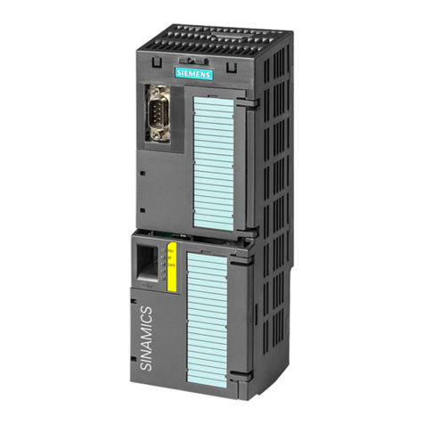
Frequency inverters with Control Units CU230P-2 HVAC, CU230P-2 DP, CU230P-2 CAN
Operating Instructions, 01/2011, FW 4.4, A5E02430659B AD 7
6.2.2.6 USS read request ......................................................................................................................128
6.2.2.7 USS write job .............................................................................................................................129
6.2.2.8 USS process data channel (PZD)..............................................................................................130
6.2.2.9 Time-out and other errors ..........................................................................................................130
6.2.3 Communication over Modbus RTU............................................................................................133
6.2.3.1 Setting the address ....................................................................................................................134
6.2.3.2 Basic settings for communication ..............................................................................................134
6.2.3.3 Modbus RTU telegram...............................................................................................................135
6.2.3.4 Baud rates and mapping tables .................................................................................................136
6.2.3.5 Write and read access via FC 3 and FC 6.................................................................................139
6.2.3.6 Communication procedure.........................................................................................................141
6.2.4 Communication via BACnet MS/TP...........................................................................................143
6.2.4.1 Setting the address ....................................................................................................................144
6.2.4.2 Basic settings for communication ..............................................................................................144
6.2.4.3 Supported services and objects.................................................................................................145
6.3 Communication over CANopen .................................................................................................152
6.3.1 CANopen functionality of the converter .....................................................................................153
6.3.2 Commissioning CANopen..........................................................................................................154
6.3.2.1 Setting the node ID and baud rate.............................................................................................154
6.3.2.2 Monitoring the communication and response of the inverter.....................................................155
6.3.2.3 SDO services .............................................................................................................................156
6.3.2.4 Access to SINAMICS parameters via SDO ...............................................................................159
6.3.2.5 PDO and PDO services .............................................................................................................161
6.3.2.6 Predefined connection set .........................................................................................................165
6.3.2.7 Free PDO mapping ....................................................................................................................166
6.3.3 Other CANopen functions..........................................................................................................167
6.3.3.1 Network management (NMT service) ........................................................................................167
6.3.4 Object directories .......................................................................................................................170
6.3.4.1 Free objects ...............................................................................................................................177
6.3.4.2 Objects in drive profile DSP402.................................................................................................178
6.3.5 Configuration example ...............................................................................................................179
7 Functions............................................................................................................................................... 183
7.1 Overview of the inverter functions..............................................................................................183
7.2 Inverter control ...........................................................................................................................185
7.2.1 Two-wire control: method 1........................................................................................................186
7.2.2 Two-wire control, method 2........................................................................................................187
7.2.3 Two-wire control, method 3........................................................................................................188
7.2.4 Three-wire control, method 1.....................................................................................................189
7.2.5 Three-wire control, method 2.....................................................................................................190
7.2.6 Switching over the inverter control (command data set) ...........................................................191
7.3 Command sources.....................................................................................................................194
7.4 Setpoint sources ........................................................................................................................195
7.4.1 Analog input as setpoint source.................................................................................................195
7.4.2 Motorized potentiometer as setpoint source..............................................................................196
7.4.3 Fixed speed as setpoint source .................................................................................................198
7.4.4 Running the motor in jog mode (JOG function) .........................................................................200
7.4.5 Specifying the motor speed via the fieldbus ..............................................................................201
7.5 Setpoint calculation....................................................................................................................202
7.5.1 Minimum speed and maximum speed .......................................................................................202
