Troubleshooting
Step 1: Remove and Replace Battery from Device
Open the battery tray on the side of the device. Remove
battery and replace with a new CR-2450 battery.
Reassemble and test operation.
Step 2: Factory Reset and Rejoin
Remove battery. Insert a paper clip into the reset hole on
the side of the device. While holding down the reset button,
reinsert battery to factory reset the device. Repeat the
“Getting Started” steps to rejoin the ZigBee network.
Specications
Power
Rated: 3V
Battery: CR-2450
Battery Life: Up to 2 years
Environmental
Operating Temperature: 0° to 40°C
Shipping/ Storage
Teperature: -20° to 50°C
Humidity Range: 0 to 90% RH. (non-condensing)
Approvals
This device complies with Part 15 of the FCC rules. Operation
is subject to the following two conditions:
(1) This device may not cause harmful interference and
(2) This device must accept any interference received,
including interference that may cause undesired operation.
Conforms to FCC Part 15B
FCC ID: T3L-SS006
IC: 12192A-SS006
Industry Canada licence-exempt RSS Standards. Operation is subject
to the following two conditions: (1) This device may not cause harmful
interference, and (2) This device must accept any interference
received, including interference that may cause undesired operation.
Under Industry Canada regulations, this radio transmitter may only
operate using an antenna of a type and maximum (or lesser) gain
approved for the transmitter by Industry Canada. To reduce potential
radio interference to other users, the antenna type and its gain should
be so chosen that the equivalent isotropically radiated power (e.i.r.p.)
is not more than that necessary for successful communication.
This equipment complies with FCC and IC radiation exposure limits
set forth for an uncontrolled environment. This equipment is in direct
contact with the body of the user under normal operating conditions.
This transmitter must not be co-located or operating in conjunction
with any other antenna or transmitter.
Changes or modications not expressly approved by CentraLite
Systems, Inc. could void the user’s authority to operate the
equipment.
Le présent appareil est conforme aux CNR d’Industrie Canada
applicables aux appareils radio exempts de licence. L’exploitation est
autorisée aux deux conditions suivantes: (1) l’appareil ne doit pas
produire de brouillage, et (2) l’utilisateur de l’appareil doit accepter
tout brouillage radioélectrique subi, même si le brouillage est
susceptible d’en compromettre le fonctionnement.
Conformément à la réglementation d’Industrie Canada, le présent
émetteur radio peut fonctionner avec une antenne d’un type et
d’un gain maximal (ou inférieur) approuvé pour l’émetteur par
Industrie Canada. Dans le but de réduire les risques de brouillage
radioélectrique à l’intention des autres utilisateurs, il faut choisir
le type d’antenne et son gain de sorte que la puissance isotrope
rayonnée équivalente (p.i.r.e.) ne dépasse pas l’intensité nécessaire
à l’établissement d’une communication satisfaisante.
Installation
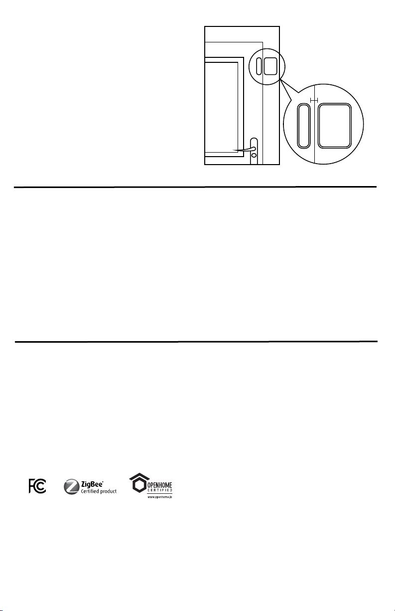
Installing on Doors
1. Place the sensor’s mounting clip on the door frame and
mark the screw hole locations with a pencil. Repeat for
magnet mounting clip on door.
Note: Sensor and magnet must be less than 1” apart when
the door is in the closed position.
2. Drill 3/16” pilot holes at each marked screw location.
3. Attach mounts using included screws, then snap the
Micro Door Sensor and magnet into their corresponding
mounts.
4. To install without screws or mounting clips, use the
included mounting tape.
Less than 1” apart
Door Frame
Door


