Centroid OAK User manual

Centroid OAK CNC Control Installation Manual
4
5
8
14
19
24
38
53
www.centroidcnc.com
OAK CNC control
Introduction and Discussion
What’s Included
Bench Testing Hardware Setup
Windows and CNC software install
Electrical Cabinet Installation
Final CNC Software Conguration
Appendices
Centroid_Oak_install_manual.pdf rev 4-10-15 Copyright © 2015 CENTROID
CNC CPU combination with AC Servo drive interface w/ built-in PLC and Spindle control
Bench Test

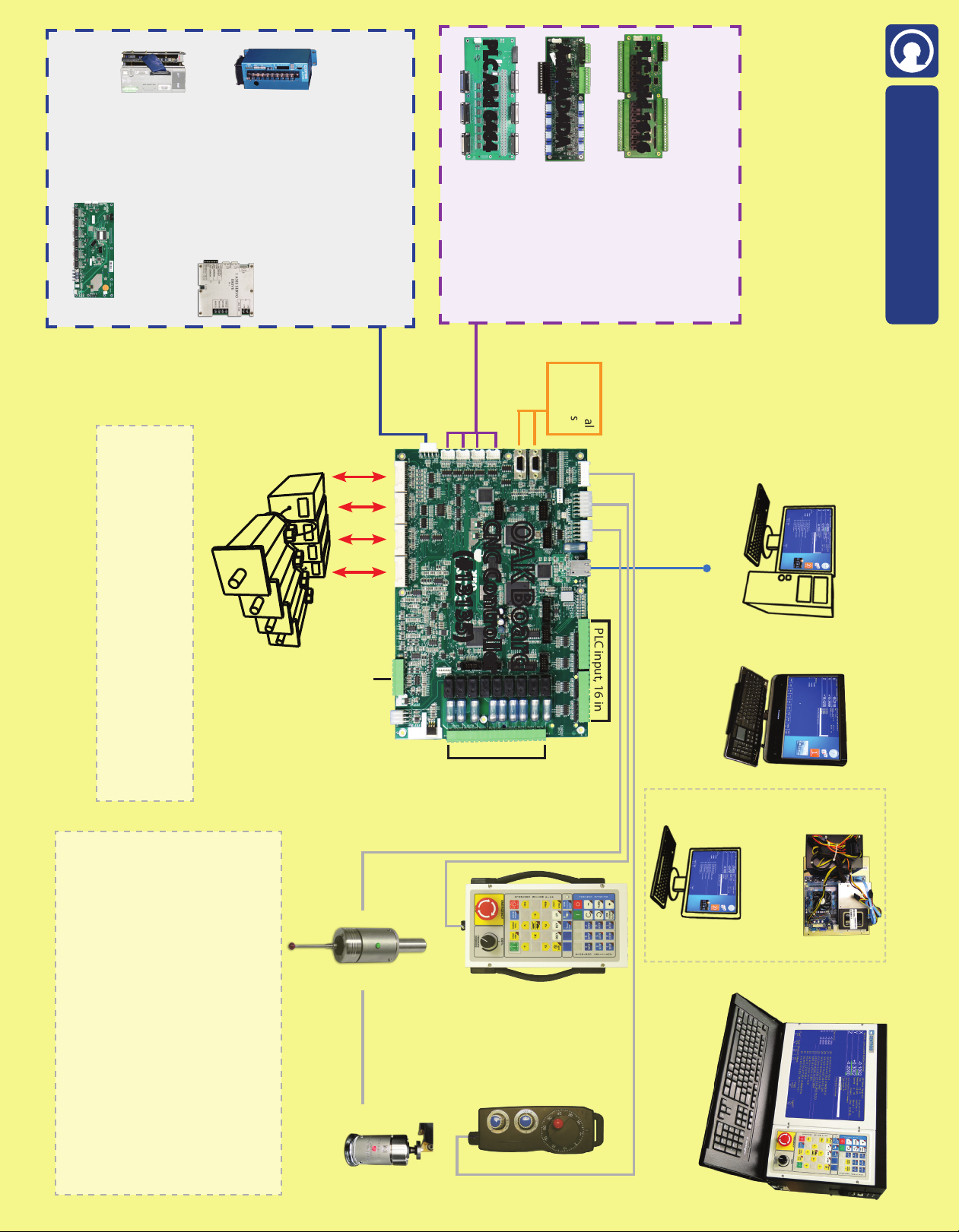
Built-in: 4-Axis 3rd Party Digital Servo Drive Interface, Spindle Control and CNC PLC (16 in/9 relay out)
with CENTROID Mill or Lathe software.
Additional
Encoders
or Scales
159 Gates Road, Howard, PA 16841 USA
(814) 353-9290
www.centroidcnc.com
PLC input, 16 in
TM OAK Board: Single board CNC Controller
16 Inputs (5, 12, 24 VDC)
16 Relay Outputs
(#11025)
4 Digital to Analog Outputs
4 Analog to Digital Inputs
(#11141)
PLC Add 1616
Add4AD4DA
Optional PLC I/O Expansion Boards
Add more I/O, up to 4 in any combination
for up to 272 In / 272Out
64 Inputs 5V non isolated
64 Outputs Open Collector
(#11212)
PLC Add 6464
Your Windows 7/8 PC
Ethernet
Cable to PC
CNC PC choices:
OR:
Our All-in-One PC
(11084tb)
Our CNC PC
cabinet mount (#11084)
& your display
OR:
OR:
Our CNC console
(#11082)
Copyright © 2012-15 CENTROID. rev7 2-10-15
All prices and specications subject to change without notice.
* at time of purchase. This price sheet supersedes all previous pricing.
Optional
Manual Pulse
Generator (MPG)
(#11069)
Optional Touch Probe&Software
DP-4 (#10405)
DP-7 (#12431)
Console, Display, & Cabinet opt. mounting hardware
- Console ext. cable in conduit (6 ft) (#11028)
- Console cable in conduit (over 6ft) (#11028)
- Console mounting arm (#10636)
- Console swivel mount (use w/ your arm) (#10834)
- Rolling cabinet stand and display tray (#10512)
- Rolling console stand (#10695)
- Display/keyboard tray with arm (#10240)
- Operators Pendant mounting hardware (#10491)
- MPG internal cable 20’ w/bulkhead con. (#11086)
- Probe internal cable 6’ w/bulkhead con. (#11085)
- Operators control panel internal cable 20’ (#11029)
- OEM/DIY console cable connector set (#13138)
Optional
Operator’s
Control Panel
(#11077)
Optional Auto Tool Set
- TT-2 (#12486)
- TT-1 (#10220)
Panel Mount console (#11170)
OAK Board
CNC Controller
(#13135)
*must meet minimum performance
requirements, you install software.
Two way digital servo
drive communication
1 2 3 4
CENTROID Servo Drive Interface
Optional: Servo drives, Optical drive interface
and Encoder expansion board.
Connect up to 4 via daisy chain
CENTROID DC1 servo drive
(#11112)
CENTROID OpticDirect drive interface
(#12554)
CENTROID Encoder
Expansion Board
(#13085)
Add up to 4 additional axes, up to 8 axes total
Yaskawa, Delta, Estun,
and many other motor-
drive packages
CENTROID AC/DC servo drive
30 amp AC/DC-30 (#12854)
60 amp AC/DC-60 (#12855)
PLC relay
output,
9 out
Analog Spindle
Control
Oak Plug and Play Drive Interface cables
Delta Interface Cable (#13131)
Estun Interface Cable (#13132)
Yaskawa Interface Cable (#13134)
“Flying lead”cable for connection to other drives (#13133)
CENTROID
(factory installed software)


Table of Co te ts
CENTROID..............................................................................................1
Oak Board Install Manual......................................................................1
Introduction............................................................................................4
Before You Begin...................................................................................4
Cha ter 1 – What's included.................................................................5
1.1 Oak Board.............................................................................................................................................................5
1.2 Cables...................................................................................................................................................................6
1.3 Overview..............................................................................................................................................................7
Cha ter 2 – Connecting Com onents for a Bench Test....................8
2.1 Bench Test – Tools and Eq ipment......................................................................................................................8
2.2 Bench Test – Power S pply Config ration..........................................................................................................9
2.3 Bench Test – Comm nication Config ration.....................................................................................................10
2.4 Bench Test – Connecting Accessories................................................................................................................11
2.5 Bench Test – Powering On & Verifying LED States..........................................................................................12
Cha ter 3 – Software Installation.......................................................14
3.1 Windows Software Preinstallation.....................................................................................................................14
3.2 CNC 11 Software Installation.............................................................................................................................15
Cha ter 4 – Configuring for a Bench Test.........................................19
4.1 Bench Test – CNC11 Software Config ration...................................................................................................19
Cha ter 5 – Electrical Cabinet Wiring................................................24
5.1 Introd ction to Electrical Cabinet Wiring..........................................................................................................24
5.2 Electrically Config ring Inp ts on the Oak Board.............................................................................................27
5.3 Install Major Components in Cabinet.................................................................................................................29
5.4 Wiring E-Stop.....................................................................................................................................................30
5.5 Wiring Limit Switches........................................................................................................................................31
5.6 Wiring L be P mp.............................................................................................................................................32
5.7 Wiring Coolant P mp.........................................................................................................................................33
5.8 Wiring Spindle....................................................................................................................................................34
5.9 Wiring 3rd Party Servo Amplifiers to the Oak Board........................................................................................37
Cha ter 6 – Final Software Configuration.........................................38
6.1 Programing yo r Third Party Drive...................................................................................................................38
6.2 Confirm Encoder Comm nication.....................................................................................................................40
Page 2 of 72
T:\_Docs worki g\Oak Board Ma ual\Oakboard i stall ma ual V2 4-10-15.odt

6.3 Clearing Software Fa lts....................................................................................................................................41
6.4 Motor Software Set p.........................................................................................................................................42
6.5 Config re Axes to Move Correct Distance........................................................................................................45
6.6 Homing the Machine..........................................................................................................................................46
6.7 T ne the PID.......................................................................................................................................................48
6.8 Backlash Compensation.....................................................................................................................................49
6.9 Software Travel Limits.......................................................................................................................................50
6.10 Performing a System Test.................................................................................................................................52
6.11 Create A Report................................................................................................................................................52
A endix A: Troubleshooting............................................................53
Error Initializing MPU11..........................................................................................................................................53
452 PC Receive Data Error......................................................................................................................................53
Jog Panel Comm nication In Fa lt..........................................................................................................................53
Axis does not move the correct distance..................................................................................................................53
Axes don't move - No Error or Fa lt displayed........................................................................................................53
F ll Power Witho t Motion, Position Errors and SV_STALL Errors......................................................................54
Motor Behaving Unexpectedly.................................................................................................................................54
A endix B: Technical Information...................................................55
A endix C: 3rd Party Drive Cable Information...............................69
Page 3 of 72
T:\_Docs worki g\Oak Board Ma ual\Oakboard i stall ma ual V2 4-10-15.odt

INTRODUCTION
This ma ual describes how to i stall the Ce troid CNC system.
Follow each step i order without skippi g steps.
The system provides up to 4 axes (upgradable to 8 axes) of closed loop servo i terpolated motio , co trolled by G-Code.
The system is i te ded for CNC co trol of milli g machi es, routers, lathes, flame, plasma, laser/water jet cutters, a d other
specialized applicatio s.
This system is i te ded to be i stalled by compete t i stallers, retro-fitters, a d machi e tool builders who wa t to do their ow
i stallatio . This i stallatio ma ual is ot i te ded for casual e d users. Users of this ma ual should be comfortable with the
followi g:
•basic wiri g
•readi g basic electrical schematics
•PC skills (copyi g, pasti g, extracti g zip files, k owledge of directories)
BEFORE YOU BEGIN
I stalli g the Ce troid CNC11 based Oak Board system is a straight forward process if the directio s are followed. Before getti g
started, please take the time to familiarize yourself with the schematics, ma uals a d i stallatio i structio s.
While doi g the i stallatio , it is very importa t that you follow the i structio s i order a d that you follow them exactly.
Your system will ot fu ctio if you attempt to take shortcuts by skippi g steps.
Doi g the i stallatio i creme tally a d testi g as you go will allow you to immediately isolate the cause of a y problems that you
may ru i to.
Troubleshooting:
•Appe dix A i cludes troubleshooti g procedures for various commo problems.
•If you ru i to a problem first refer to the troubleshooti g procedure, the the Appe dix.
•If the problem persists after exhausti g all other optio s, visit ce troidc c.com a d fill out a help request form, fou d
u der the tech su ort tab.
•Fee based pho e support is also available if eeded.
Page 4 of 72 Before You Begi
T:\_Docs worki g\Oak Board Ma ual\Oakboard i stall ma ual V2 4-10-15.odt

CHAPTER 1 – WHAT'S INCLUDED
1.1 OAK BOARD
The followi g compo e ts are i cluded with your Oak Board:
1. Oak Board ..................................................................................................................... Part Number 13126
2. Power supply.................................................................................................................... Part Number 7135
3. Power supply Output cable............................................................................................. Part Number 13106
4. Seve positio termi al block...........................................................................................Part Number 2611
5. Twe ty positio termi al block..........................................................................................Part Number 3450
6. 2 Te positio termi al block............................................................................................Part Number 3904
7. 4 Twelve volt SIPs (color a d appeara ce may vary).......................................................Part Number 4152
8. 4 Five volt SIPs (color a d appeara ce may vary)...........................................................Part Number 3956
Page 5 of 72 1.1 Oak Board
T:\_Docs worki g\Oak Board Ma ual\Oakboard i stall ma ual V2 4-10-15.odt
2 Power Su ly
3
4
1 Oak Board
5
67
8
SIPs
Power Su ly
Out ut Cable
Terminal Block

1.2 CABLES
Ce troid offers the followi g cables for purchase:
1. Probe Cable (multiple le gths available) ........................................................................Part Number 11211
2. Jog Pa el Cable (multiple le gths available) (Supplied with Jog Pa el)..............Part Number 12991 (10 ft)
3. MPG Cable (multiple le gths available)...............................................................Part Number 12987 (10 ft)
4. Ether et Cable (multiple le gths available)..............................................................Part Number 6144 (6 ft)
5. Drive Cable................................................................................................................... Part Numbers Below
Drive Centroid Part Number
Delta ASDA-A2 13131
Estu 13132
Yaskawa Sigma I, II, V 13134
Flyi g Lead 13133
6. Co sole Exte sio Cable (exte sio s available)....................................................Part Number 11028 (6 ft)
◦I cludes Jog, MPG, Ether et. Co sole Power, a d E-stop cables
Page 6 of 72 1.2 Cables
T:\_Docs worki g\Oak Board Ma ual\Oakboard i stall ma ual V2 4-10-15.odt
1 Probe Cable 2 Jog Panel Cable
3 MPG Cable 4 Ethernet Cable 5 Drive Cable

1.3 OVERVIEW
Page 7 of 72 1.3 Overview
T:\_Docs worki g\Oak Board Ma ual\Oakboard i stall ma ual V2 4-10-15.odt

CHAPTER 2 – CONNECTING COMPONENTS FOR A BENCH TEST
The first step i i stalli g the ew system is performi g a be ch test. A “be ch test” co sists of co ecti g all of the electro ics
together to test them before i stalli g the system i a machi e.
The be ch test ALWAYS eeds to be performed BEFORE applyi g HIGH VOLTAGE to the drive, ot be ch testi g could cause
physical harm to the tech icia or operator a d perma e t damage to the hardware.
2.1 BENCH TEST – TOOLS AND EQUIPMENT
•Picking a good location: A be ch test eeds to be performed o a large table or desk with good lighti g a d easy
access to electrical outlets.
◦A clean wooden surface is an ideal test bench location.
◦The surface should NOT be made out of metal or co tai metal scraps or shavi gs.
•Some method of poweri g the board o a d off. A outlet strip with a “o /off” switch a d some 120VAC power cords is
the recomme ded a d easiest method.
•A PC with a i ter et co ectio , or a Ce troid co sole u it (comes with CNC11 already i stalled).
Note: The PC must meet the specificatio s listed i Tech ical Bulleti 273, which ca be fou d here:
(http://www.ce troidc c.com/dealersupport/tech_bulleti s/uploads/273.pdf)
•Small screw driver set
•Digital Multimeter
•Some method of splici g wires such as crimp termi als or a termi al block.
•Wire Strippers
Page 8 of 72 2.1 Be ch Test – Tools a d Equipme t
T:\_Docs worki g\Oak Board Ma ual\Oakboard i stall ma ual V2 4-10-15.odt

2.2 BENCH TEST – POWER SUPPLY CONFIGURATION
Connect Oak Board to the ower su ly: Follow the i structio s below.
1) Co ect the supplied cables to the Mea Well power supply a d the plug labeled Power o the Oak board. Co ect
positio 1 a d 2 from H1 o the Oak Board to V4 a d COM respectively.
2) Splice a 110 V power cord to the power supply AC i put. Live to L, Neutral to N, a d Grou d to grou d.
Page 9 of 72 2.2 Be ch Test – Power Supply Co figuratio
T:\_Docs worki g\Oak Board Ma ual\Oakboard i stall ma ual V2 4-10-15.odt
Figure 2.2.1
Power Supply Co ected
to Oak Board
Twisted Wires Not I cluded
Hot 110 V (cable ot i cluded)
Neutral 110 V (cable ot i cluded)
Grou d 110V (cable ot i cluded)
V3, +24 V (H2 positio 1)
-V4 (-12 V)
+V2 V (+12 V)
COM (multiple wires)
+5 V
110 V from power strip
( ot i cluded)
COM
Black
G d
Gree
+V2 V
Yellow
+5V
Red
COM
Black
-V4
Blue
Looki g at fro t of plug

2.3 BENCH TEST – COMMUNICATION CONFIGURATION
Connect the Shielded Ethernet Cable: Co ect a shielded Ether et cable from your Oak Board to the PC.
•A shielded Ether et cable will have a metal clip arou d the RJ-45 co ector as show o the cable o the right i Figure
2.3.1.
•Ce troid recomme ds usi g s agless patch cables from StarTech. Use the shortest practical cables.
This i formatio is outli ed i Tech ical Bulleti 251. The latest versio ca be fou d here:
http://www.ce troidc c.com/dealersupport/tech_bulleti s/uploads/251.pdf
Note: A u shielded cable ca cause i termitte t PC Data receive errors i the software due to electro ic oise a d
i terfere ce.
Length (ft) Centroid Part Number
6 6144
15 7269
25 6143
Page 10 of 72 2.3 Be ch Test – Commu icatio Co figuratio
T:\_Docs worki g\Oak Board Ma ual\Oakboard i stall ma ual V2 4-10-15.odt
Figure 2.3.2
U shielded Ether et cable (left) compared to
Shielded Ether et cable (right)
Figure 2.3.1
Ether et cable co ected to PC

2.4 BENCH TEST – CONNECTING ACCESSORIES
Connect Any Accessories: Co ect optio al accessories
•If a Jog Pa el/Pe da t or MPG was ordered, please co ect it to the Oak Board as see i Figures 2.4.1 a d 2.4.2.
Page 11 of 72 2.4 Be ch Test – Co ecti g Accessories
T:\_Docs worki g\Oak Board Ma ual\Oakboard i stall ma ual V2 4-10-15.odt
Figure 2.4.2
MPG
Figure 2.4.1
Jog Pe da t

2.5 BENCH TEST – POWERING ON & VERIFYING LED STATES
Before you begin:
Before poweri g o , verify that othi g metallic ca touch the circuit boards a d cause a short. Make sure all wiri g is firmly i
place.
Switch the outlet stri on: Poweri g the Oak Board a d a y accessories.
Oak Board Status LED states:
After 15-30 seco ds the status LED's should all be solid o except for DEBUG, which should flash o ce per seco d, a d DF,
which does 't tur o u til the software is i stalled.
Figure 2.5.1 shows where these status LED's are located.
If they are ot all o , or the DSP DEBUG is flashi g faster tha o ce per seco d, refer to the table below for troubleshooti g.
Page 12 of 72 2.5 Be ch Test – Poweri g O & Verifyi g LED States
T:\_Docs worki g\Oak Board Ma ual\Oakboard i stall ma ual V2 4-10-15.odt
-12 LED
5 LED
3.3 LED
PLC OK
DF
FPGA OK
DBUG
DSP OK
Bli ks o ce per seco d
+12 LED
Off U til
Co ected
to Computer
ON ON ON ON ON ON ON
Figure 2.5.1
Status LEDs o the Oak Board
Bli ks o ce per seco d

Oak Board Status LED Troubleshooting
LED Sym tom Possible Cause Corrective Action
All status LED's out Logic power ot applied Measure AC comi g i to power supply,
correct wiri g or supply problems
5, 3.3, 12, or -12 LED out Power supply or
co ectio problem
Measure AC comi g i to power supply,
correct wiri g or supply problems
FPGA LED ot lit Oak ot ready Wait 45 seco ds
I ter al Fault Retur for repair
DSP LED ot lit Oak is booti g up Wait 45 Seco ds
DSP DEBUG LED flashi g fast Detecti g hardware Wait to detect hardware
DSP DEBUG LED flashi g o e
time per seco d
New drive protocols
active No e, ormal operatio
DSP DEBUG LED flashi g two
times per seco d
Legacy drive protocols
active
I ter al fault, o ly ew protocols should be i
use, retur for repair
DF LED out
Motio co trol
processor sectio
has 't booted up
Start software, wait for the mai scree to
load
"Servo Power
Removed" due to fault
Restart system to reset ru away or other
serious fault co ditio
PLC OK LED out
Motio co trol
processor sectio
has 't booted up
Start software, wait for the mai scree to
load
LED1 display flashi g with decimal
poi t lit
A error co ditio has
bee detected
See the "LED1 Error Codes" sectio i Oak
Ma ual for details o the error
Page 13 of 72 2.5 Be ch Test – Poweri g O & Verifyi g LED States
T:\_Docs worki g\Oak Board Ma ual\Oakboard i stall ma ual V2 4-10-15.odt
LED1 Display
Figure 2.5.2
LED1 Display

CHAPTER 3 – SOFTWARE INSTALLATION
3.1 WINDOWS SOFTWARE PRE-INSTALLATION
1. If a console unit or com uter was urchased from Centroid, it already comes with Wi dows properly co figured a d
the CNC11 software already i stalled.
If using your own com uter, it must meet the prerequisites listed i TB 273 posted here:
(http://www.ce troidc c.com/dealersupport/tech_bulleti s/uploads/273.pdf)
If using windows 8, you must follow the procedure outli ed i TB 283:
(http://www.ce troidc c.com/dealersupport/tech_bulleti s/uploads/283.pdf)
If using windows 7, you must follow the procedure outli ed i TB 244:
(http://www.ce troidc c.com/dealersupport/tech_bulleti s/uploads/244.pdf)
Note: Microsoft Wi dows Xp, Vista, a d older versio s of Wi dows are ot supported. Mac OS a d Li ux operati g
systems are also ot supported.
2. Before installing CNC11 all anti-virus, anti-malware, and 3rd arty firewall software should be uninstalled (not
disabled) and the com uter rebooted.
•Turn off windows Firewall:
1) Click the start butto
2) Search for “firewall”, click o Windows Firewall
3) Click Turn Windows Firewall on or off
4) Click Turn off Windows Firewall
5) Click OK
•Nearly 100% of all communication roblems between CNC11 and the Oak Board are caused by anti-virus and
3rd arty firewall software. Virus software almost always detects the i teractio betwee the Oak Board a d the
PC as u usual/suspicious a d i terferes with the operatio of CNC11. Firewalls ofte block the ports eeded for the
operatio of CNC11.
•If your corporate policy requires a ti-virus software, a third party firewall, or that certai Wi dows security features be
e abled to co ect to the etwork, the Ce troid recomme ds that you keep a y computers with CNC11 i stalled
disco ected from the etwork.
Page 14 of 72 3.1 Wi dows Software Pre-i stallatio
T:\_Docs worki g\Oak Board Ma ual\Oakboard i stall ma ual V2 4-10-15.odt

3.2 CNC 11 SOFTWARE INSTALLATION
With your be ch co figuratio completely powered as described i Sectio 2.4 a d your PC powered up, i stall the CNC11
Software as follows:
1. Download the latest CNC11 Software version:
The latest versio ca be fou d here: CNC11 Software dow load
(http://www.ce troidc c.com/usersupport/support_files/latest_release/c c11_latest.zip)
2. Co y the downloaded file to your deskto :
Depe di g o your Wi dows 7 setti gs, the file you dow loaded will be displayed as either cnc11_win7_latest.zi or
cnc11_win7_latest. Copy this file to your desktop a d the double click o the file from your desktop.
3. Drag the installation folder from the com ressed file to your deskto as shown below in Figure 3.2.1:
E ter or extract the c c11_wi 7_latest folder, you will see the i stallatio folder i side.
The i stallatio folder i this example is called centroid-cnc11-v314. The “v314” sig ifies the CNC11 versio , yours may
be ewer, do ot use a versio lower tha v314 with the Oak Board. Copy this to the desktop.
4. Double click the centroid-cnc11-v314 folder. Then double click “setu ” to begin CNC11 install as seen in Figure
3.2.2
5. Wi dows may ask “Do you want to allow the following program from an unknown publisher to make changes on this
computer?”
Click “Yes”.
Page 15 of 72 3.2 CNC 11 Software I stallatio
T:\_Docs worki g\Oak Board Ma ual\Oakboard i stall ma ual V2 4-10-15.odt
Figure 3.2.1
Copy to desktop
Figure 3.2.2
Double click Setu

6. Select CNC11 Mill a d WinPca for a Mill i stallatio as show i Figure 3.2.3.
Select CNC11 Lathe a d WinPca for a Lathe i stallatio .
Click Next, accept default i stallatio servo drive a d directory (c:\) a d click Install as see i Figure 3.2.4. The software
will extract as show i Figure 3.2.5.
7. Install WinPca : Click “Next” i the Wi Pcap Setup Wizard wi dow as circled i Figure 3.2.6.
Check the “Automatically start the WinPca at boot” box whe prompted ( ot show ).
8. Click “Next” to continue: After the Wi Pcap i stallatio has fi ished, click “Next.”
Page 16 of 72 3.2 CNC 11 Software I stallatio
T:\_Docs worki g\Oak Board Ma ual\Oakboard i stall ma ual V2 4-10-15.odt
Figure 3.2.3
Select CNC11 a d Wi Pcap Figure 3.2.4
Select the C drive
Figure 3.2.5
Software i stallatio
Figure 3.2.6
I stallatio complete

9. Network Ada ter Setu : Click the dow arrow to display the etwork adapters that are curre tly i stalled.
Select the etwork adapter that is co ected to the Oak Board as circled i Figure 3.2.7.
Disconnect all ethernet cables from the PC exce t for the one connecting to the Oak Board. The Oak Board should
be powered
If you see multiple optio s, retur to step 4 a d make sure o ly the Oak Board is plugged i to the ether et ports.
Note: Your IP address will differ from those show i the picture.
Note: Ce troid recomme ds usi g a computer with two Ether et ports. O e Ether et port is used for the Oak Board,
a d the seco d Ether et port ca be used to access the i ter et or a LAN.
Click Next to co ti ue.
Whe asked if you would like to cha ge the IP address for the adapter selected, click “yes”.
Page 17 of 72 3.2 CNC 11 Software I stallatio
T:\_Docs worki g\Oak Board Ma ual\Oakboard i stall ma ual V2 4-10-15.odt
Figure 3.2.7
Select the etwork adapter that is co ected to the Oak

10. Installing a PLC rogram: After the CNC11 software has bee i stalled, the i staller will prompt you to i stall a PLC
program, select Yes.
Click o the + sig s ext to Mill or Lathe a d click _OAK.
Click o _basic
Click Install as show i Figure 3.2.8.
Note: the plc i staller ca be fou d i the same folder as setup, the dow load li k is i the begi i g of this sectio .
11. Click “Finish” to com lete CNC11 software installation.
12. Power off everything and restart.
Page 18 of 72 3.2 CNC 11 Software I stallatio
T:\_Docs worki g\Oak Board Ma ual\Oakboard i stall ma ual V2 4-10-15.odt
Figure 3.2.8
I stall the PLC program
Figure 3.2.9
PLC i staller
Other manuals for OAK
1
Table of contents
Other Centroid Control Unit manuals
Popular Control Unit manuals by other brands

Infineon
Infineon GPT12 PWM Capture 1 manual

Agilent Technologies
Agilent Technologies 54751A manual

M-system
M-system R8-SVT8 instruction manual

SystemBase
SystemBase Eddy Series user guide

BEINAT
BEINAT BX280 Installation and user guide

Roger Technology
Roger Technology H70/104AC Instructions and warnings for installation

ARI-Armaturen
ARI-Armaturen BR 012 ZESA Operating and installation instruction

Norgren
Norgren VR10 Operation & service manual

GYS
GYS 025981 operating manual

Siemens
Siemens RS-485 operating instructions

IFM
IFM AS interface E70188 installation instructions

motogadget
motogadget m.unit blue Operating and installation guide