Centroid DP-7 User manual

DP-7 Touch Probe
Operator's Manual
U.S Patent #6553682
Rev 2013-11-11
Copyr ght © 2003-2013 Centro d Corporat on
Howard, PA 16841

DP-7 Quick Start Guide
1. Install MPU11 Probe cable assembly #11085 if necessary. Refer to Common Cables
picture on page 12 connection diagram on page 13 and appropriate appendix for
parameter settings and upgrade information.
2. Connect coil cord to DP-7 and to bulkhead connector on probe cable assembly
#11085. See probe features and general description page 1. LED indicating light will
alternate colors during power up and initialization and the probe outputs are exercised
also as a diagnostic tool at this time
3. Set system control parameters. See “Table of Contents” to locate application specific
appendix for a list of parameter settings and upgrade information.
4. Confirm machine is responding to DP-7 input by running an automatic cycle without the
probe in the spindle and manually touching the DP-7 stylus mount boss. Refer to
control operator's manual for automatic probing cycles. Follow the “Initial Control/Probe
Setup Procedures” in the appendix appropriate for your control.
5. Install the DP-7 and tool holder in the spindle then install the stylus in the DP-7. See
Stylus handling and installation procedures on page 4 and perform run-out adjustment
as shown on page 5.
6. Review stylus travel limits on page 3 and perform an automatic probing cycle at
reduced speed.
7. Calibrate stylus tip size. See procedures on page 9.
8. Review Adjustments page 3 4 and 5 and Maintenance and Care page 9 to keep DP-7
in good operational condition.
9. Probe is now ready to use.

TABLE OF CONTENTS
General Description Page 1
Over Travel Limits and Dimensions Page 2
Specifications Page 3
Stylus Assembly Installation and Alignment Procedures Page 4
Run-out Adjustment “Dialing-in” Page 5
When to check run-out Page 7
Angular Alignment Page 7
Angular Alignment Adjustment Procedure Page 8
Initial Control / Probe set up procedure Page 9
Stylus Tip Diameter Calibration Page 9
Maintenance and Care Page 10
Shipping Instructions Page 11
Kit Contents Page 12
Common Cables Page 13
Connection Diagram (universal) Page 14
Grid Digitizing Tips Page 15
Cutting a Copy of Digitized Part Tips Page 16
Appendix A – CNC10 Centroid Control System Application Page 17
Upgrading from DP-4 and DP-4D
Appendix B – CNC11 Centroid Control System Application Page 21

DP-7 PROBE GENERAL DESCRIPTION AND SPECIFICATIONS
GENERAL DESCRIPTION:
The DP-7 was designed for applications that require minimal pre-travel variation (PTV) such
as digitizing, measuring and pro ing in varying directions. The DP-7 can maintain minimal
pre-travel variation while using stylus assem lies much longer than other pro es. The DP-7
features pre-travel correction technology making it the o vious choice for demanding high
accuracy applications.
The user should first ecome familiar with the various parts and features of the pro e as
shown a ove to facilitate assem ly, installation, cali ration and maintenance. Read the stylus
installation and alignment procedures section efore attempting assem ly. Review the over-
travel limits shown in the specifications. Exceeding the limits will damage the pro e and stylus
assem ly.
The DP-7 is factory tested and adjusted using the stylus components it is shipped with.
Specify the required stylus assem ly when ordering to minimize the num er of adjustments
necessary during set up. Off the shelf stylus components rarely align properly when first
assem led.
A high quality 5 pin connector through the pro e ody provides a convenient disconnect point
for the stock 6 foot retractile cord. A short retractile cord is also availa le.
Last Modified 2014-09-16 04:12:44 AM Page 1 of 21
C:\Users\Keith\AppData\Local\Temp\7zO0E521723\DP7 ody20140916.odt
Mounting shank
Run-out adjustment screws
Use 3/32” hex wrench
LED indicator light
ngular alignment screws
Rubber seal
Stylus mount boss
Stylus tightening hole
DP-7 RE R VIEW
Electrical
connector
Body
Stylus stem
Stylus tip
DP-7 FRONT VIEW
Stylus stem base

The DP-7 works with the Centroid control to minimize pre-travel variation. CNC11 systems
are plug-in ready for the DP-7. CNC10 systems require an additional installation kit. See the
Centroid appendix for CNC10 installation kit information.
DP-7 SPECIFICATIONS:
Last Modified 2014-09-16 04:12:44 AM Page 2 of 21
C:\Users\Keith\AppData\Local\Temp\7zO0E521723\DP7 ody20140916.odt
OVER TR VEL LIMITS ND DIMENSIONS
10°10°
0.15”
3.8mm
0.5” ø
12.7mm
1.3” ø
33mm
1.5”
38mm
2.64”
67mm

DP-7 SPECIFICATIONS:
Pro ing directions X+/-, Y+/-, Z-
Unidirectional repeata ility (2 sigma) 0.00004” (1 micron)
Pro e deflection force (X,Y) 5 ounce nominal with 40mm stylus
Pre-travel variation X,Y,Z <0.0009” with 140 mm stylus
Pro e deflection force (Z) 35 ounce nominal
Pro e ody diameter and length D= 1.30” (33.1mm) L= 2.64” (67.2mm)
Mounting shank diameter and length D= 0.50” (12.7mm) L= 1.50” (38.2mm)
Stylus mount thread M3
Output signals Sinking (FET open drain) up to 30V 50mA
Output logic normally open
Power supply required 10 – 30 VDC 50mA
LED status indicator green = ready, red = tripped, flashing = travel warning
Weight of pro e and ½”shank 0.55 l
Over travel limit angle (X,Y) +/- 10 degrees from vertical
Over travel limit (Z-) 0.150” (4.3mm)
Environmental IP54, Dust Proof
Last Modified 2014-09-16 04:12:44 AM Page 3 of 21
C:\Users\Keith\AppData\Local\Temp\7zO0E521723\DP7 ody20140916.odt

STYLUS ASSEMBLY INSTALLATION AND ALIGNMENT PROCEEDURES
Important: Read the complete procedure efore starting.
The DP-7 is factory adjusted for the stylus and stylus extension that are supplied with it.
Using other stylus components will pro a ly require some adjustment. When assem ling
stylus extensions do not twist or apply torque to the car on fi er or ceramic composite
section. Use the supplied 0.035” hex wrenches to tighten the stylus assem ly as explained
elow.
Req ired Tools:
3/16” open end wrench
0.035” hex wrench (two of these)
0.001" or etter Dial Indicator with Magnetic Base
0.500" Dedicated Tool Holder
STEP 1: Thread the 0.25” ru y tip stylus into the car on fi er stylus extension. Use the
supplied 035” hex wrenches to tighten the stylus assem ly, insert a wrench through the hole
nearest to the joint to e tightened. See photos elow. Never apply torque to the car on fi er
section of the stylus extension assem ly. Apply force with thum and finger to the hex
wrench ends to tighten the threads. Do not end the hex wrenches. If the hex wrenches are
ending too much force is eing applied. Be careful not to drop or end the stylus assem ly.
It is very rigid and will e damaged y mechanical shock and stress.
STEP 2: Install the DP-7 Pro e into a dedicated 0.500" tool holder and into the machine
spindle.
Last Modified 2014-09-16 04:12:44 AM Page 4 of 21
C:\Users\Keith\AppData\Local\Temp\7zO0E521723\DP7 ody20140916.odt

STEP 3: Thread the stylus assem ly into the stylus mount oss on the DP-7. Insert a
wrench into the hole located closest to stylus mount oss. Place the 3/16" wrench, on the
flats of the stylus mount oss. Refer to the pictures elow.
Use thum and finger to apply torque to the hex wrench. Do not apply any twisting force with
the 3/16" open end wrench; use the wrench to counter act the twisting force eing applied y
the hex wrench in the hole. Excessive twisting force applied to the pro e through the stylus
mount oss could damage the internal sensor assem ly! If the 035” hex wrench egins to
end too much force is eing applied.
RUN-OUT ADJUSTMENT:
The run-out adjustment procedure, is necessary to ensure that the center of the pro e stylus
tip is aligned with the center of the spindle rotation axis. This eliminates any unexpected off-
set when digitizing or doing automated part set-up.
STEP 1: Position the dial indicator, as shown in the photo elow, with the finger of the dial
indicator on the front and center of the stylus all.
Last Modified 2014-09-16 04:12:44 AM Page 5 of 21
C:\Users\Keith\AppData\Local\Temp\7zO0E521723\DP7 ody20140916.odt

Run-out Adjustment set-up and effect of Set Screw Movement
STEP 2: Rotate the spindle y hand (without touching the pro e) so that the pro e spins
through a full 360 degrees and watch the dial indicator to locate the high and low run-out
rotation positions of the stylus. Adjust the dial indicator so that the entire run-out of the tip can
e seen on the dial. If the run-out exceeds the range of the dial then egin at the highest point
of the run-out and set the dial indicator so it is at the limit of its range at this point.
STEP 3: Rotate the pro e to locate the max run-out location. Rotate the pro e so that
the nearest run-out adjustment set screw is a ove the finger tip of the indicator. Only adjust a
set screw when it is directly a ove the indicator finger. This way you can see the full effect of
the adjustment you are making. Using the 3/32" hex wrench slowly turn the setscrew directly
a ove the indicator finger, in the counter clock-wise direction, the dial indicator will show the
reduction in the run-out. Do not allow the pro e to ecome loose on the mounting shank.
Rotate the pro e to the set screw that was nearest the low run-out and position the set screw
directly a ove the finger of the dial indicator. Insert the 3/32” hex wrench in the run-out
adjustment set screw and tighten. Watch the dial indicator to see the effect of the adjustment.
STEP 4: Repeat step 3 as many times as necessary, minimizing force and deflection of
the dial indicator each time. Adjust until no run-out of the tip is visi le on the dial indicator
needle. If the screws ecome too tight efore you have finished the adjustment, do not force
them, instead loosen the setscrew that corresponds with the highest reading on the dial
indicator and tighten the set screw at the lowest reading. Only adjust a set screw when it is
directly a ove the indicator finger. This way you can see the full effect of the adjustment you
are making. When all three set screws are equally tight and no run-out is visi le on the dial
indicator needle the adjustment is complete.
Last Modified 2014-09-16 04:12:44 AM Page 6 of 21
C:\Users\Keith\AppData\Local\Temp\7zO0E521723\DP7 ody20140916.odt

WHEN TO CHECK RUN-OUT:
Any time the pro e is removed from its holder, the stylus is changed or the pro e is used in a
different machine, the alignment procedure should e repeated to ensure accuracy. The user
should also repeat the alignment procedure if the unit receives any sudden external shock. It
is good practice to periodically check alignment for quality control and to esta lish a ase line
maintenance schedule.
ANGULAR ALIGNMENT:
Angular alignment is the relation of the spindle center line to the stylus stem center line. This
adjustment provides for equal clearance all around the stylus stem. This adjustment is rarely
needed except when an extremely small tip or long stylus is used. When the stylus tip and
stem are nearly the same diameter this adjustment is critical to keep the stem from contacting
a vertical surface efore the tip. This adjustment is also convenient to adjust parallelism when
flat disc or lock stylus types are used. The range of adjustment is very small as it is only
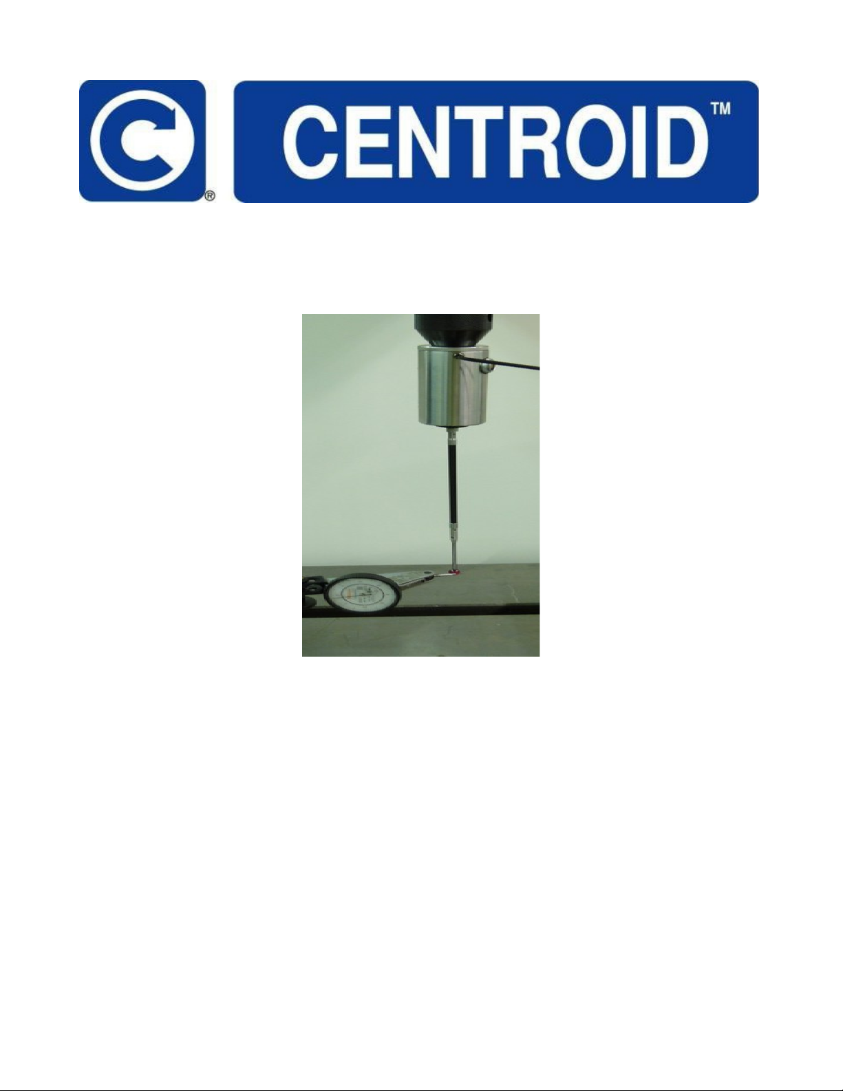
intended to correct the stylus and spindle center line alignment. If this adjustment must e
performed use the run-out adjustment set-up shown a ove to monitor the effect of the
adjustment. The angular alignment and run-out adjustments are interdependent. It will e
necessary to repeat each several times to achieve significant results. When completed, the
run-out at the stylus mount end of the stylus stem should e nearly the same as the run-out at
the tip. Adjust the stylus tip run-out last.
WHEN TO CHECK ANGULAR ALIGNMENT:
The DP-7 when shipped with a long stylus assem ly is aligned for that assem ly at the
factory. When replacing stylus assem lies with off the shelf parts it is likely adjustment will e
needed. Check the angular alignment any time stylus parts have een first assem led,
changed or adjusted.
CHECKING ANGULAR ALIGNMENT:
To check the angular alignment egin y checking run-out at the pro e tip. Adjust the tip run-
out to zero. Measure the run-out at the ase of the stylus stem (the end at the stylus mount
oss) with the dial indicator. If the run-out is greater than the difference etween the cali rated
tip diameter and stem diameter then it will e possi le for the stem to contact a vertical
surface efore the tip (also called “shanking out”). Adjustment is necessary if it is possi le for
the stylus to shank out.
Last Modified 2014-09-16 04:12:44 AM Page 7 of 21
C:\Users\Keith\AppData\Local\Temp\7zO0E521723\DP7 ody20140916.odt

ANGULAR ALIGNMENT PROCEDURE:
The angular alignment procedure has a high degree of difficulty. Read this entire section and
e certain adjustment is necessary efore attempting it. Consider having Centroid (TM)
perform this adjustment, test the pro e and install any up-grades that may e applica le to
continue relia le performance. If this is a new installation it is unlikely this adjustment is
needed unless damage has occurred in shipping. In that case the pro e should e returned
for service.
The six angular alignment screws are interdependent. The Phillips head screws are in tension
and the socket head set screws are in compression. The pro e core is suspended and
oriented y these screws. Use the dial indicator setup as shown in the run-out adjustment
section. Make adjustment when the screw is vertically aligned with the indicator tip to directly
monitor the effect of the adjustment.
STEP 1: Adjust the run-out to zero at the stylus stem ase using the run-out adjustment
set screws.
STEP 2: Measure run-out at the tip. At the point of least run-out loosen the nearest
Phillips head screw(s) a small amount (¼ turn) and tighten the nearest socket head set
screw(s). Maintain a minimum load on all screws at all times.
STEP 3: Measure run-out at the stylus stem ase. The adjustments done in step 2 will
cause it to change. Use the run-out adjustment set screws to again minimize the run-out.
STEP 4: Repeat steps 2 and 3 until run-out at the tip and ase is less than 0.002”. Adjust
the run-out at the tip to zero using the run-out adjustment set screws. Measure run-out at the
stylus stem ase. It must e less than the cali rated tip diameter minus the stem diameter
minus any additional allowance for over-travel.
STEP 5: Be sure all screws are equally tight when finished.
Last Modified 2014-09-16 04:12:44 AM Page 8 of 21
C:\Users\Keith\AppData\Local\Temp\7zO0E521723\DP7 ody20140916.odt

INITIAL CONTROL/PROBE SETUP PROCEDURE
STEP 1: Confirm that control parameters are setup correctly for your system. The
automatic pro ing cycles will not work if the parameters are not correctly set. See appendix
to check the default parameter settings for the appropriate control system. Check the control
operation manual if compati le parameter settings are not found in the appendix.
STEP 2: Plug the retractile cord into the DP-7 pro e and into the digitizing port on the
control. The cord ends are keyed to prevent incorrect connection. At the pro e end line-up the
red dot with the red painted slot on the pro e connector, push the plug in until it clicks. At the
opposite cord end insert the large lack connector and rotate until it drops into the digitizing
port connector then finger tighten the securing ring to seat the connector. The LED indicating
light on the front of the pro e alternately flash red and green. The pro e outputs also turn on
and off as the LED flashes as a diagnostic tool.
STEP 3:
Review the pro e overtravel limits in the specifications on page 2. Perform an automatic
pro e cycle test with the feedrate over ride reduced to 20% and the stylus 10 inches away
from any o ject to verify everything is working together. Be prepared to manually stop the
machine to prevent overtravel damage to the pro e. From the main screen, press <F1-
Setup>, then <F1-part>, then <F5-Pro ing>, then <F7-Single Axis>, and finally <Cycle Start>.
The control will jog the stylus in the direction of the single axis move selected. Touch the
stylus once and the control will stop and reverse travel the pro e clearance amount then stop
and then resume motion in the single axis direction at the slow pro e rate. Touch the stylus
once more and the control will stop and display a position window. Repeat this step and
adjust parameters as needed to gain confidence using the automated cycles.
STYLUS TIP DIAMETER CALIBRATION PROCEDURE:
The pro e stylus tip diameter must e cali rated to compensate for any fixed signal delays or
deflections in the pro ing process. Inconsistent delays, feedrate and machine characteristics
will result in variations in the pro ing and digitizing data. Repeating the cali ration procedure
many times will give an indication of the range of error due to inconsistent factors. Be sure
the feedrate over-ride is set at 100% for the automated portions of this procedure. The control
commands in this procedure are for Centroid (TM) systems. Consult your control manual for
equivalent commands.
STEP 1: On the mill ta le, fixture the precision ring gauge from the pro e tool kit. The ring
must lie flat with the center line of the ore aligned with the center line of the pro e stylus.
Note the diameter of the gauge. Be sure the pro ing parameters are set correctly. See the
appendix appropriate for your application.
STEP 2: Jog the pro e over the center (roughly) of the ring gauge, and then slowly jog the
Z-axis down until the tip of the pro e is inside the ore and not touching anything.
Last Modified 2014-09-16 04:12:44 AM Page 9 of 21
C:\Users\Keith\AppData\Local\Temp\7zO0E521723\DP7 ody20140916.odt

STEP 3: From the main screen, press <F1-Setup>, then <F1-part>, then <F4-Pro ing>,
Set your pro e diameter to 0.000 in the field provided and press enter, then <F1-Bore>,and
finally <Cycle Start>. The control will jog the stylus to and pro e each quadrant of the ore. It
will then return to the center of the ore. A message ox will appear on the screen that will
display the measured diameter of the ore. Su tract this num er from the known diameter of
the gauge ore. The resulting num er will e the cali rated diameter of the pro e stylus tip.
STEP 4: Test the result. press <F4-Pro ing>, Enter the cali rated pro e diameter in the
field provided and press enter, then <F1-Bore>,and finally <Cycle Start>. The control will jog
the stylus to and pro e each quadrant of the ore. The message ox will appear on the screen
and will display the measured ore diameter within +/- 0.0002" if the cali rated tip diameter is
correct and the machine is in good condition. Adjust tip cali ration diameter and repeat as
needed.
STEP 5: Go to the Tool Li rary and enter the cali rated diameter for the pro e stylus in
the tool# you assigned to the pro e. Cali ration complete.
MAINTENANCE AND CARE
Do not s bmerge or expose the DP-7 to liquids. Wipe off any liquids immediately to prevent
internal contamination or degradation of the ru er seal and indicator lens. The pro e ody is
stainless steel and should only e wiped clean with compati le cleaners.
Storage. When not in use, store the pro e in a vertical or inverted vertical position, not on its
side. This minimizes stress on internal mechanical parts and distri utes lu rication more
evenly. Do not ship or store the pro e with the stylus mount oss pushed into the pro e ody
as this will negatively affect internal lu rication.
User repairs. The DP-7 has no internal user servicea le parts or adjustments and should
only e serviced y Centroid.
Alignment adj stments. Regularly check alignment. Any time the pro e is removed from its
holder, the stylus is changed or the pro e is used in a different machine, the alignment
procedure should e repeated to ensure accuracy. The user should also repeat the alignment
procedure if the unit is dropped or receives any sudden external shock. It is good practice to
periodically check alignment for quality control and to esta lish a ase line maintenance
schedule. See "Stylus Installation and Alignment Procedures" section. If the pro e stylus can
not e dialed-in or aligned then the pro e should e sent in for evaluation and repair.
The DP-7 has no internal user servicea le parts or adjustments and should only e serviced
y Centroid. If your pro e should require repair please contact Centroid Technical Support at
1-814-353-9290 for a description of the return policy and assistance in determining if return is
necessary, efore sending your pro e ack.
Last Modified 2014-09-16 04:12:44 AM Page 10 of 21
C:\Users\Keith\AppData\Local\Temp\7zO0E521723\DP7 ody20140916.odt

SHIPPING INSTURCTIONS
If the pro e must e shipped it should e removed from the tool holder and the stylus
assem ly must e removed from the pro e. Use the original plastic shipping tu e and insert
the pro e in the tu e with the stylus mount oss located inside the foam ring in the tu e. The
foam should prevent the stylus mount oss from touching the end of the plastic tu e if jarred
during shipping. Do not ship or store the pro e with the stylus mount oss pushed into the
pro e ody as this will negatively affect internal lu rication.
Last Modified 2014-09-16 04:12:44 AM Page 11 of 21
C:\Users\Keith\AppData\Local\Temp\7zO0E521723\DP7 ody20140916.odt

DP-7 PROBE KIT CONTENTS
Last Modified 2014-09-16 04:12:44 AM Page 12 of 21
C:\Users\Keith\AppData\Local\Temp\7zO0E521723\DP7 ody20140916.odt
0.035” hex wrench p/n: 2509 Qty 2
Precision ring gauge p/n: 3193
Size and type may vary
3/32” hex wrench p/n: 2898
DP-7 Probing package with protective case
and accessories. Inset shows outside of case.
Kit contains the accessories shown above
plus: retractile coil cord p/n: 10394
100mm carbon fiber extension p/n: 6658
.25” diameter ruby tip stylus p/n: 3510
Complete kit p/n: 12431
3/16” wrench p/n: 2902

COMMON CABLES:
The photo elow shows the DP-7 connected to the primary ca le assem lies common to all
installations. Note the ulkhead connector to provide physical support for the coil cord. No
additional adapters are needed for new Centroid (TM) CNC11 systems. See the appropriate
appendix in the this manual for additional required adapters, connection diagrams and
parameter settings for specific applications.
Last Modified 2014-09-16 04:12:44 AM Page 13 of 21
C:\Users\Keith\AppData\Local\Temp\7zO0E521723\DP7 ody20140916.odt
COIL CORD
72” long P/N: 10394
36” long P/N: 11040
MPU11 Probe Cable P/N:1108
Internal wiring harness with fuse
holder and bulkhead connector to
mate with COIL CORD.

CONNECTION DIAGRAM UNIVERSAL
Last Modified 2014-09-16 04:12:44 AM Page 14 of 21
C:\Users\Keith\AppData\Local\Temp\7zO0E521723\DP7 ody20140916.odt

GRID DIGITIZING TIPS
Digitizing is, y its nature, a slow, precise process. The time it takes to digitize a part is
effected y four factors: feedrate, step size, detail density and over-all shape of the o ject.
The fast pro ing feedrate parameter setting controls the speed to find the surface. A second
approach to the surface after it is found is done at the slow pro ing or measuring feedrate.
This will provide the high accuracy required of part setup and measurement. The two hit
method optimizes speed and accuracy. The two hit method is not time efficient for digitizing.
Knowledge of the surface to e digitized is used to plan a grid approach at a fixed feedrate to
collect surface data. The speed selected for the digitizing run is a trade-off of time and
accuracy. Less time, less accuracy. More time, more accuracy. Additionally higher feedrates
induce vi ration in the machine frame and add to the digitizing errors. A few short test runs
can determine the optimal feedrate.
The accuracy achieved digitizing 3 dimensions is dependent on stylus length and related
PTV (pre-travel variation) for the pro e eing used. See the performance characteristics
section for an example of PTV. Pro ing and part setup that is always done in a single
direction can e handled y a pro e that simply has good repeata ility. Good repeata ility is
not a su stitute for low PTV. The DP-7 was developed specifically for 3D digitizing accuracy
with long stylus assem lies. Determine the accepta le digitizing error for the project, the
pro e PTV (3D) must e less than the accepta le error.
The X, Y, and Z stepover – The smaller the stepover distance, the longer the digitizing run.
For instance the typical time it takes to digitize a 1” y 1” grid with a step over of .010” in X,
and .010” in Y, (with parameters 14 and 15 set to 30ipm and 5ipm respectively), is 45 minutes
with 10,000 data points eing recorded. By changing the X stepover to 0.005” and the Y
stepover to 0.005” the time increases to 3 hours with the num er of data points recorded
increasing to 40,000. The trade off with time, is surface finish and detail. The finer the
stepover amount in the digitizing run the etter the surface finish is going to e in the final part
and the more fine detail you will e a le to capture. As the end user, it is up to you to find the
settings that give you the finish, and detail level you are looking for in the final part.
Remem er, the Centroid control can digitize unattended, 24 hours a day, 7 days a week, if
you really need the detail and finish, (just remem er to fill the automatic oiler tank!).
The third factor that affects the time it takes to digitize a part is the density and height of the
surface detail. The more vertical walls the pro e stylus must clim , up and down over, the
longer the digitizing will take. This is not a factor you have much control over, except for
adjusting your Z stepup distance, ut in general this will have little effect.
Finally, if the piece is odd shaped, you may want to patch several small digitizing runs
together and there y eliminate the wasted time that would e spent moving over areas that
are not pertinent to the data you want to collect.
Last Modified 2014-09-16 04:12:44 AM Page 15 of 21
C:\Users\Keith\AppData\Local\Temp\7zO0E521723\DP7 ody20140916.odt

CUTTING COPY OF DIGITIZED PART TIPS:
The following are some tips on using the data from your completed grid digitizing run. The
nomenclature, procedures and programs used are consistent with the Centroid(TM) operators
manual. Consult your operator's manual for equivalent.
When you are ready to cut a copy of the part you have digitized, set your part up using the
same X, Y, and Z coordinate you used to digitize the part. The digitizing program does not put
in the M codes and spindle speed setting. You must either turn the spindle on manually or
edit the G-code file and insert this information. Simply insert a line at the eginning of the
program that contains M3 (spindle clockwise) or M4 ( spindle counter clockwise) followed y
an S with the speed you want to turn the spindle at.
The following is an example: M3 S4000
This will turn the spindle on going clockwise at 4000 RPM. To turn the spindle off when the
program finishes put a M5 at the end of the program.
You can also use the text editor to turn coolant on and off y adding, M7 (MIST), or M8
(FLOOD) at the eginning of the program, and M9 (COOLANT OFF) at the end. Remem er
you can have only one-M code per line in the program.
To enlarge, shrink or mirror your part, you can use the G51 (turns on scaling) and G50 (turns
off scaling) commands, (refer to your user manual for the complete description and definition
of these G code commands). When enlarging or shrinking your part using the G51 command
remem er you must scale the size of the cutter you are going to use to cut the part y the
same factor that you use to scale your part. For instance if you digitized a part with a 0.25”
stylus and scale the part up y 2 then the cutter needed to cut the part would e a 0.5”
diameter cutter. Conversely if you scale the part y ½ then the cutter diameter needed would
e 0.125”.
You can also import your digitized data into an online CAM program on your Centroid control
or export it to an offline CAM system.
Last Modified 2014-09-16 04:12:44 AM Page 16 of 21
C:\Users\Keith\AppData\Local\Temp\7zO0E521723\DP7 ody20140916.odt

APPENDIX A
Up grading CNC10 system with RTK3 PLC from DP-4 to DP-7
Photo 1. Components of up graded pro ing system
Component descriptions:
1) RTK3 PLC swap out unit with firmware 071206 or newer
2) DSP CONDUIT CABLE assem ly num er 10956
3) CPU10B swap out unit with cyclone rev 071106 and IO2PIC 071207 or newer
4) INTBRD daughter card with jumpers set for DP7 operation
5) PROBE COIL CORD assem ly num er 10394
6) RTK3 DIGITIZE CABLE with splice connectors
7) DP-7 PROBE
Photo 1. shows the general interconnection of the components for the DP-7 up grade. The
splice connections are not made until all the ca les have een routed. The DSP conduit
ca le must e pulled through the conduit to the console where the CPU10B is located.
Control software must e updated to support the operation of the DP-7.
Last Modified 2014-09-16 04:12:44 AM Page 17 of 21
C:\Users\Keith\AppData\Local\Temp\7zO0E521723\DP7 ody20140916.odt
2
4
3
1
5
6
7
Table of contents
Other Centroid Test Equipment manuals
Popular Test Equipment manuals by other brands

Reichert Technologies
Reichert Technologies Ametek Multi-Chek user guide

Keysight Technologies
Keysight Technologies N4877A Getting started

ComSonics
ComSonics SnapTRACK Series user manual

EXFO
EXFO FVA-60B user guide

Fluke Calibration
Fluke Calibration P3031 user manual

Dräger
Dräger Alcotest 5000 Instructions for use