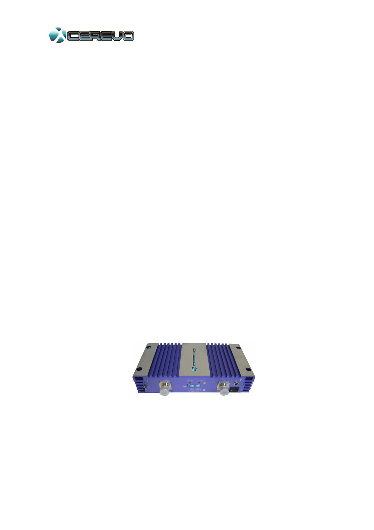
User’s Manual for CR-SIG09WB-20
www.cerevotech.com
1.2 Safety Warnings
1 Repeater must be installed following user’s manual strictly,
and assure good groundings and lightning for delivering
repeaters stable protection.
2 The power supply of repeater should meet the standards of
security.
3 Any user should disconnect power prior to operate repeater.
4 Do not carry out any modification or internal components
adjustment. The adjustment or repair of the equipment must
only be produced by trained and authorized personnel.
5 For better heat-dissipation, please keep the repeater away
from other electrical appliances, and do not cover repeater
with anything.
6 For the purpose of regular supervision or maintenance,
please pay attentions to the indicator lights during operation.