USER MANUAL FOR MBDA-200
Copyright - refer to title page
0.2 INDEX TO FIGURES AND TABLES
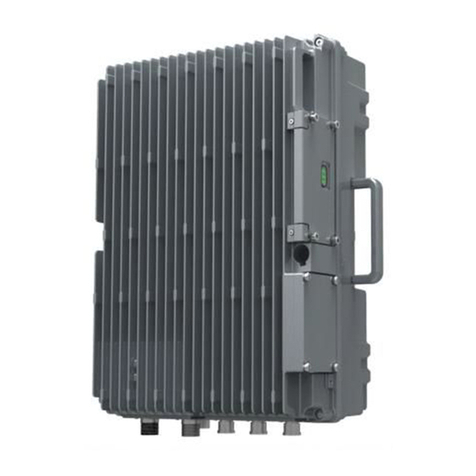
Figure 1: mBDA-200.................................................................................................................................................10
Figure 2: System Diagram.......................................................................................................................................11
Figure 3: Layout of mBDA .......................................................................................................................................12
Figure 4: mBDA Screen...........................................................................................................................................17
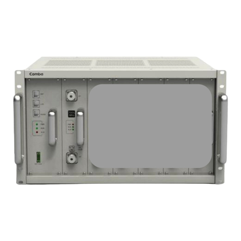
Figure 5: mBDA Rack...............................................................................................................................................18
Figure 6: Remove Cover Plates..............................................................................................................................18
Figure 7: PMU Installation .......................................................................................................................................19
Figure 8: RF Unit Installation...................................................................................................................................19
Figure 9: mBDA Installation Finish.........................................................................................................................20
Figure 10: Equipment Cabinet with Pallet.............................................................................................................21
Figure 11: mBDA Installation ..................................................................................................................................21
Figure 12: Secure the Screws.................................................................................................................................22
Figure 13: Finish Installaiton ...................................................................................................................................22
Figure 14: Mounting Rack........................................................................................................................................23
Figure 15: Angle Iron Installation............................................................................................................................23
Figure 16: mBDA Installation ..................................................................................................................................24
Figure 17: Secure the Enclosure............................................................................................................................24
Figure 18: Finish Installaiton ...................................................................................................................................25
Figure 19: mBDA Front Panel Connectors...........................................................................................................26
Figure 20: mBDA Rear Panel Connectors............................................................................................................26
Figure 21: mBDA Grounding (mBDA Rear Panel)...............................................................................................28
Figure 22: mBDA Power Connection (Rear Panel) .............................................................................................29
Figure 23: Pins Allocation for “EXT_ALM” Port for mBDA.................................................................................29
Figure 24: Commissiong Flow Chart......................................................................................................................31
Figure 25: PC IP Address Setting...........................................................................................................................33
Figure 26: Input IP Address.....................................................................................................................................33
Figure 27: Input Domain Name...............................................................................................................................33
Figure 28: Input User Name and Password..........................................................................................................34
Figure 29: Web GUI Main Screen ..........................................................................................................................34
Figure 30: [Devices] Sceen .....................................................................................................................................35
Figure 31: Power & Monitoring Unit.......................................................................................................................35
Figure 32: RF Unit.....................................................................................................................................................36
Figure 33: RF Unit Detail Information ....................................................................................................................37
Figure 34: [Commissioning] Screen.......................................................................................................................37
Figure 35: [Firmware] Screen –Upgrade..............................................................................................................38
Figure 36: [Firmware] Screen –Pop-up Window 1..............................................................................................38
Figure 37: [Firmware] Screen - Swap....................................................................................................................39
Figure 38: [Management] Sceen............................................................................................................................39
Figure 39: Management –Import&Export.............................................................................................................40
Figure 40: Management –IP Setting.....................................................................................................................41
Figure 41: Management –SNMP Setting..............................................................................................................41
Figure 42: Management –Security........................................................................................................................42
Figure 43: Modify Password....................................................................................................................................42
Figure 44: Management –Device Reset...............................................................................................................43
Figure 45: Management –PA Reset......................................................................................................................43
Figure 46: Management –Device Info...................................................................................................................44
Figure 47: Management –Isolation........................................................................................................................44
Figure 48: Management –Report...........................................................................................................................45
Figure 49: Commissioning Procedure - Start........................................................................................................45
Figure 50: Commissioning Procedure –Site Info. Setting..................................................................................46
Figure 51: Dev Info & Date/Time............................................................................................................................46
Figure 52: Commissioning Procedure –Isolation Detective...............................................................................47
Figure 53: Commissioning Procedure –Isolation Detective Confirm................................................................47
