Cerio OW-200N2 User manual

CERIO Corporation
OW-200N2
500mW eXtreme Power 11Na
Outdoor Bridge
User’s Manual
V2.0

Table of Contents
1 Introduction................................................................................................................................4
1.1 Overview .....................................................................................................................4
1.2 System Concept .........................................................................................................4
1.3 Applications in Wireless Network.............................................................................5
1.4 Product Benefit.........................................................................................................12
1.5 Package Contents ....................................................................................................12
1.6 Features ....................................................................................................................13
1.7 Panel Function Description .....................................................................................17
1.8 Hardware Installation Steps.....................................................................................17
1.9 Software Configuration............................................................................................18
Router AP Mode Configuration ...................................................................................................23
2. Router AP Mode Configuration ...............................................................................................24
2.1 External Network Connection..................................................................................24
2.2 Wireless LAN Network Creation ..............................................................................31
2.3 Wireless Network Expansion...................................................................................48
2.4 System Management ................................................................................................50
2.5 Access Control List ..................................................................................................62
2.6 Resource Sharing .....................................................................................................71
2.7 System Status ...........................................................................................................74
AP Mode Configuration ..............................................................................................................84
3 AP Mode Configuration.........................................................................................................85
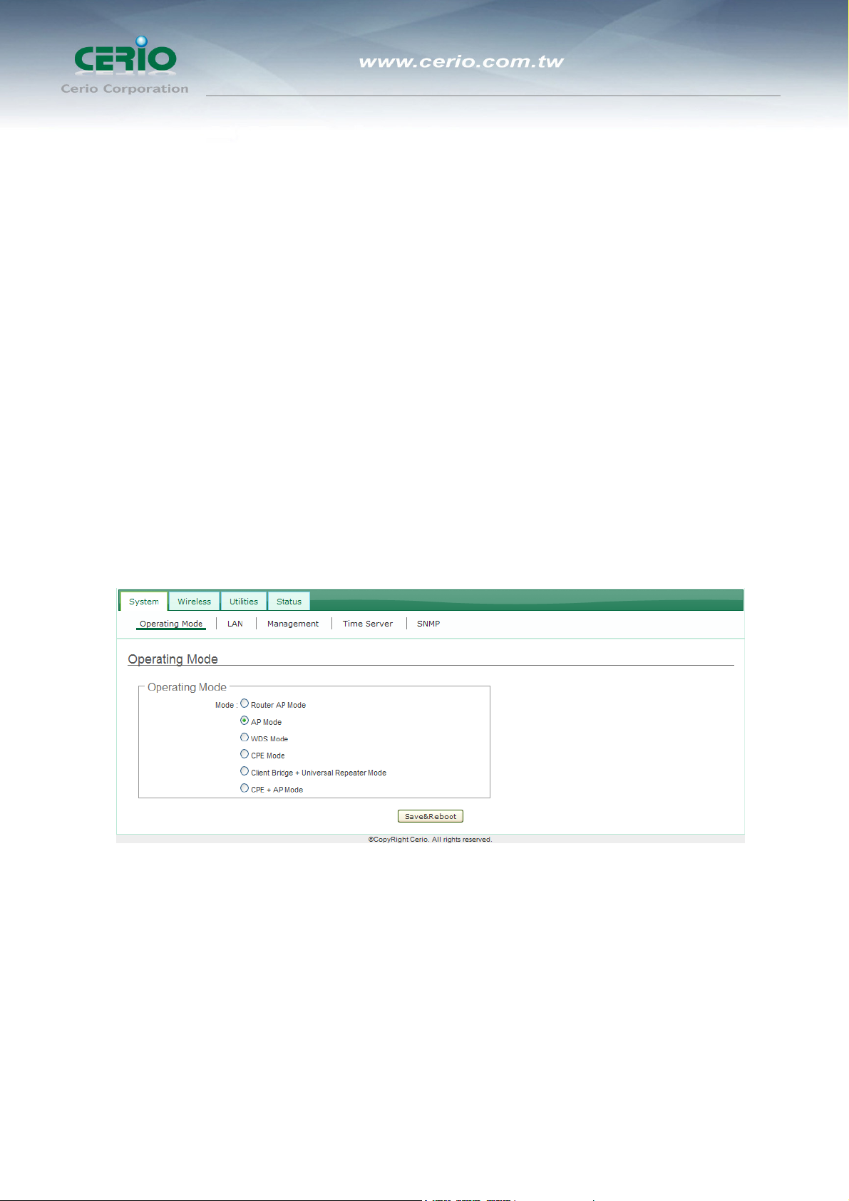
3.1 Chose Your Operating Mode ...................................................................................85
3.2 External Network Connection .................................................................................85
3.3 Configure OW-200N2 LAN IP Address....................................................................86
3.4 Wireless LAN Network Creation..............................................................................89
3.5 Advanced Setup .......................................................................................................91
3.6 Create Virtual AP (VAP)..........................................................................................100
WDS Mode Configuration.........................................................................................................110
4 External Network Connection .............................................................................................110
4.1 Network Requirement ............................................................................................110
4.2 Configure OW-200N2 LAN IP Address..................................................................112
4.3 Wireless Network Expansion.................................................................................115
4.4 Advanced Setup .....................................................................................................119
4.5 WDS Setup ..............................................................................................................128
CPE Mode Configuration..........................................................................................................130
5 External Network Connection .............................................................................................131
5.1 Network Requirement ............................................................................................131
5.2 Configure WAN Setup ............................................................................................132
5.3 Configure LAN Setup .............................................................................................136
5.4 Configure DDNS Setup ..........................................................................................138
5.5 Configure Wireless General Setting .....................................................................139
5.6 Station Site Survey.................................................................................................141
5.7 Create Wireless Profile ..........................................................................................142
5.8 Advanced NAT Function ........................................................................................146
5.9 Access Control List (IP Filter Setup) ....................................................................149
5.10 Access Control List (MAC Filter Setup)................................................................151
5.11 QoS Setup ...............................................................................................................152
Clinet Bridge + Universal Repeater Mode Configuration ..........................................................130
6 External Network Connection .............................................................................................157
6.1 Network Requirement ............................................................................................157

6.2 Configure LAN Setup .............................................................................................158
6.3 Configure Wireless General Setting .....................................................................162
6.4 Wireless Advanced Setup......................................................................................165
6.5 Site Survey..............................................................................................................172
6.6 Create Wireless Profile ..........................................................................................173
6.7 Wireless LAN Network Creation............................................................................175
7 CPE + AP Mode Configuration..........................................................................................184
7.1 External Network Connection................................................................................185
7.2 Access Point Association ......................................................................................194
7.3 Wireless LAN Network Creation ............................................................................208
7.4 System Management ..............................................................................................215
7.5 Access Control List ................................................................................................229
7.6 Resource Sharing ...................................................................................................238
7.7 System Status .........................................................................................................242
8 System Management ........................................................................................................253
8.1 Configure Management..........................................................................................251
8.2 Configure System Time .........................................................................................255
8.3 Configure UPnP......................................................................................................256
8.4 Configure SNMP Setup ..........................................................................................257
9 Uility.......................................................................................................................................259
9.1 Backup / Restore and Reset to Factory................................................................259
9.2 Firmware Upgrade..................................................................................................260
9.3 Network Utility ........................................................................................................261
9.4 Reboot .....................................................................................................................263
10 System Status...................................................................................................................266
10.1 System Overview.....................................................................................................264
10.2 Clients .....................................................................................................................267
10.3 Show WDS Status...................................................................................................268
10.4 Extra Information....................................................................................................269
10.5 Event Log ................................................................................................................272
Appendix A. Windows TCP/IP Settings ............................................................................276
Appendix B. WEB GUI Valid Characters .........................................................................279
Appendix C. MCS Data Rate..............................................................................................284
Appendix D. System Manager Privileges.........................................................................286
Appendix E. Enabling UPnP in Windows XP ...................................................................288
Product Specification.............................................................................................................288

User’s Manual
500mW eXtreme Power 11Na Outdoor Bridge
4
1 Introduction
1.1 Overview
The CERIO OW-200N2 500mW eXtreme Power 11Na Outdoor AP/ Bridge of connection
to Wireless Outdoor Network for service provider deploying last mile services to business
or residential broadband subscribers. Network administrators can create multiple
subscriber service tier using per-subscriber rate limiting features, and manage centrally.
for WISP bridge utilizes a 500mW output Tx Power connect to the WiFi mesh or WDS
infrastructure and provides the subscriber with an Ethernet connection for a local access
to extend the range and increase the performance of our wireless network. The outdoor
bridge may connect to the WiFi MESH or WDS infrastructure and provides the subscriber
with an Ethernet connection for a local access. Also with included PoE, power and data
are supplied to the unit using CAT5 Ethernet cable. CERIO OW-200N2 500mW eXtreme
Power 11Na Outdoor AP/ Bridge supports four operational modes, the AP mode and the
WDS mode and the CPE mode and Universal Repeater Mode , respectively with built-in
remote management features simplify the deployment and reduce cost for continued
maintenance of the outdoor bridge .
1.1.1 Access Point: It can be deployed as a traditional fixed wireless Access Point.
1.1.2 Repeater: To expand wireless service by repeating prior AP.
1.1.3 WDS: It can be used to expand Ethernet network via wireless WDS Link.
1.1.4 AP+WDS: Not only to extend Ethernet network, but also provide wireless access to
the expanded network.
1.1.5 CPE (Customer Premises Equipment): It is a wireless gateway with NAT and DHCP
Server functions to connect to Wireless Internet Service Provider's (WISP).
1.1.6 Client Bridge + Universal Repeater: It is a wireless repeater or bridge to connects to
Wireless Internet Service Provider's (WISP).
1.2 System Concept
The OW-200N2 is not only designed and used as traditional outdoor AP, but also with rich
features tailored for WISP applications. The two-level management capability and access
control ease WISP and owners to maintain and manage wireless network in a more
controllable fashion. Main applications are listed as follows with illustration:
1.2.1 Wireless CPE for Multi Dwelling Unit/Multi Tenant Unit(MDU/MTU) complexes
including apartments, dormitories, and office complexes.

User’s Manual
500mW eXtreme Power 11Na Outdoor Bridge
5
1.2.2 Outdoor Access Point for school campuses, enterprise campuses, or manufacture
plants.
1.2.3 Indoor Access Point for hotels, factories, or warehouses where industrial grade
devices are preferred.
1.2.4 Public hotspot operation for café, parks, convention centers, shopping malls, or
airports.
Wireless coverage for indoor and outdoor grounds in private resorts, home yards, or gulf
course communities.
1.3 Applications in Wireless Network
OW-200N2 is a multiple mode system which can be configured either as a wireless
gateway or an access point as desired. It also can be used WDS link for Ethernet network
expansion. This section depicts different applications on Router AP Mode, AP Mode,
WDS Mode, CPE Mode, Client Bridge + Universal Repeater Mode and CPE + AP
Mode.
1.3.1 Configuration on Router AP Mode (Gateway + Access Point + WDS)
1.3.1.1 Example 1 : Router AP without WDS
It can be deployed as a gateway with wireless Access Point

User’s Manual
500mW eXtreme Power 11Na Outdoor Bridge
6
1.3.1.2 Example 2 : Router AP with WDS
It can be deployed as a gateway with wireless Access Point and provides WDS link for network
extension.
1.3.2 Configuration in AP Mode (including Access Point + WDS)
An access point can be either a main, relay or remote base station. A main base
station is typically connected to a wired network via the Ethernet port. A relay base
station relays data between main base stations and relay stations or remote base
stations with clients. A remote base station is the end point to accept connections
from wireless clients and pass data upwards to a network wirelessly.
1.3.2.1 Example 1: Access Point without WDS
It can be deployed as a tradition fixed wireless Access Point

User’s Manual
500mW eXtreme Power 11Na Outdoor Bridge
7
Example 2: Access Point with WDS
It can be deployed as a tradition fixed wireless Access Point and provides WDS link to
expand network
Connection type 1. Connect with remote AP through WDS and provide network connection for
wireless users.
Connection Type 2. Connect with remote AP through WDS and also both provide network connection
for wireless and Ethernet users.

User’s Manual
500mW eXtreme Power 11Na Outdoor Bridge
8
1.3.3 Configuration in WDS Mode (Pure WDS)
An access point can be either a main, relay or remote base station. A main base
station is typically connected to a wired network via the Ethernet port. A relay base
station relays data between main base stations and relay stations or remote base
stations with clients. A remote base station is the end point to accept connections
from wireless clients and pass data upwards to a network wirelessly. In this mode, it
can support single or multiple WDS links and no wireless clients can associate with it
though.
1.3.3.1 Example 1: Point-to-Point
]
1.3.3.2 Example 2: Point-to-Multi-Point

User’s Manual
500mW eXtreme Power 11Na Outdoor Bridge
9

User’s Manual
500mW eXtreme Power 11Na Outdoor Bridge
10
1.3.3.3 Example 3: Multi-Point Repeating bridge
1.3.4 Configuration in CPE Mode
It can be used as an Outdoor Customer Premises Equipment (CPE) to receive
wireless signal over last mile application, helping WISPs deliver wireless broadband
Internet service to residents and business customers. In the CPE mode, OW-200N2
is a gateway enabled with NAT and DHCP Server functions. The wired clients
connected to OW-200N2 are in different subnet from those connected to Main Base
Station, and, in CPE mode, it does not accept wireless association from wireless
clients.
1.3.5 Configuration in Client Bridge + Universal Repeater Mode
It can be used as an Client Bridge + Universal Repeater to receive wireless signal
over last mile applications, helping WISPs deliver wireless broadband Internet service
to new residential and business customers. In this mode, OW-200N2 is enabled with
DHCP Server functions. The wired clients of OW-200N2 are in the same subnet from
Main Base Station and it accepts wireless connections from client devices.

User’s Manual
500mW eXtreme Power 11Na Outdoor Bridge
11
1.3.6 Configuration on CPE + AP Mode (Router Client + Access Point)
It can be used as an Outdoor Customer Premised Equipment(CPE) to receive
wireless signal over the last mile, helping WISPs deliver wireless broadband Internet
service to new residential and business customers. In this mode, the OW-200N2 is a
gateway with NAT and DHCP Server functions. The wireless and wired clients of
OW-200N2 are on the different subnet from Main Base Station and it accepts
wireless connections from client devices.

User’s Manual
500mW eXtreme Power 11Na Outdoor Bridge
12
1.4 Product Benefit
1.4.1 IEEE 802.11n Draft 2.0 Compliance in 2Tx / 2Rx Design
1.4.2 Support IEEE 802.11n and 802.11a
1.4.3 Operates in the 5GHz ISM Band
1.4.4 Enables Bandwidth of up to 300Mbps(Tx), 300Mbps(Rx) link rate
1.4.5 Topology : Point to Point ; Point to Multi Point
1.4.5.1 Router AP Mode
1.4.5.2 Access Point Mode: Pure Access Point Function and Access Point
/Bridge(WDS) Function
1.4.5.3 WDS Mode
1.4.5.4 CPE Mode (Router Client )
1.4.5.5 Client Bridge + Universal Repeater Mode
1.4.5.6 CPE + AP Mode
1.4.6 Security with 802.1X, WPA, and WPA2
1.4.7 Support QoS(Quality of Service) & WMM
1.4.8 Integrated Power over Ethernet (PoE)
1.4.9 Multiple Virtual AP & Capability of Client Isolation
1.4.10 Business-class WLAN Security and Client Authentications
1.4.11 Provide Advanced Wireless Setting
1.4.12 Support Web Management and SNMP MIB II
1.4.13 Over Load Current Protection
1.4.14 Wide Range Voltage Support (12-68VDC)
1.4.15 Weather-Proof Housing (IP 68 Approved), M-13 RJ45 and N-Type Connector
1.4.16 Client Isolation Through Layer 2 VLAN Technology
1.4.17 Two administrator accounts for manager authorities
1.4.18 QoS for bandwidth management and traffic prioritization
1.5 Package Contents
1.5.1 OW-200N2 Main Unit x 1
1.5.2 PoE-S48V: Fast Ethernet PoE Injector Switching Power Supply x 1
1.5.3 Wall / Pole Mounting Bracket x 1
1.5.4 CD manual x 1
1.5.5 Warranty Card x 1
1.5.6 Mounting Kit (Device Holder / Screws) x 2

User’s Manual
500mW eXtreme Power 11Na Outdoor Bridge
13
1.6 Features
1.6.1 Networking
1.6.1.1 Support Static IP, Dynamic IP(DHCP Client) and PPPoE on WiFi WAN
Connection
1.6.1.2 Support PPTP/L2TP/IP Sec Pass Through
1.6.1.3 PPPoE Reconnect – Always On , On demand, Manual
1.6.1.4 MAC Cloning
1.6.1.5 DHCP Server in CPE and Client Bridge + Universal Repeater Mode
1.6.1.6 802.3 Bridging
1.6.1.7 Masquerading (NAT)
1.6.1.8 Proxy DNS
1.6.1.9 Dynamic DNS
1.6.1.10 NTP Client
1.6.1.11 Virtual DMZ
1.6.1.12 Virtual Server (Port Forwarding)
1.6.1.13 Support MAC Filter
1.6.1.14 Support IP Filter
1.6.1.15 Bandwidth traffic Shaping
1.6.2 Wireless Feature
1.6.2.1 Transmission power control: 1~100 %
1.6.2.2 Channel selection : Manual or Auto
1.6.2.3 No of associated clients per AP : 32
1.6.2.4 Setting for max no associated clients : Yes
1.6.2.5 No. of ESSID (Virtual AP ): 7
1.6.2.6 No. of Max. WDS setting: 4
1.6.2.7 Preamble setting : Short/ Long
1.6.2.8 Setting for 802.11a/n mix or 802.11a only

User’s Manual
500mW eXtreme Power 11Na Outdoor Bridge
14
1.6.2.9 Setting for transmission speed
1.6.2.10 Dynamic Wireless re-transmission
1.6.2.11 IEEE802.11f IAPP (Inter Access Point Protocol), hand over users to
another AP
1.6.2.12 IEEE 802.11i Preauth (PMKSA Cache )
1.6.2.13 IEEE 802.11h - TPC(Transmission Power Control) and DFS(Dynamic
Frequency Select)
1.6.2.14 IEEE 802.11d -Multi country roaming
1.6.2.15 Wireless Site Survey
1.6.2.16 Channel Bandwidth setting: 20MHz or 20/40MHz
1.6.2.17 HT Tx/Rx Stream selection: 1 or 2
1.6.2.18 A-MSDU and A-MPDU support
1.6.2.19 Maximal MPDU density for TX aggregation setting
1.6.2.20 Short Slot support
1.6.2.21 RTS Threshold and Fragment Threshold support
1.6.3 Authentication/ Encryption (Wireless Security)
1.6.3.1 Layer 2 User Isolation and AP Isolation
1.6.3.2 Blocks client to client discovery within a specified VLAN
1.6.3.3 WEP 64/ 128 Bits
1.6.3.4 EAP-TLS + Dynamic WEP
1.6.3.5 EAP-TTLS + Dynamic WEP
1.6.3.6 PEAP/ MS-PEAP + Dynamic WEP
1.6.3.7 WPA (PSK +TKIP)
1.6.3.8 WPA (802.1x certification + TKIP)
1.6.3.9 802.11i WPA2 (PSK + CCMP/ AES)
1.6.3.10 802.11i WPA2 (802.1x certification + CCMP/ AES)
1.6.3.11 Setting for TKIP/ CCMP/ AES key’s refreshing period
1.6.3.12 Hidden ESSID support
1.6.3.13 Setting for “Deny ANY “ connection request
1.6.3.14 MAC Address filtering (MAC ACL)
1.6.3.15 No. of registered RADIUS servers: 1
1.6.3.16 VLAN assignment on ESSID

User’s Manual
500mW eXtreme Power 11Na Outdoor Bridge
15
1.6.3.17 Support WEP, AES and TKIP data encryption over WDS link

User’s Manual
500mW eXtreme Power 11Na Outdoor Bridge
16
1.6.4 Quality of Service
1.6.4.1 Download and Upload traffic control
1.6.4.2 Packet classifications via DSCP (Differentiated Services Code Point)
1.6.4.3 Control Policy by IP/IP Ranges/ MAC Group/ Service
1.6.4.4 Layer-7 Protocol Support
1.6.4.5 Traffic Analysis and Statistics
1.6.4.6 No. of Max. Policy setting: 10
1.6.4.7 DiffServ/ ToS
1.6.4.8 IEEE802.1p/ CoS
1.6.4.9 IEEE 802.1Q Tag VLAN priority control
1.6.4.10 IEEE802.11e WMM

User’s Manual
500mW eXtreme Power 11Na Outdoor Bridge
17
Panel Function Description
There is several LED indicators on the front of the OW-200N2. Please refer to the
definitions below :
Front Panel Rear Panel
1.6.4.11 Reboot Button: Unscrew the screw and click Reset button to restart
system or reset to default configurations, Press and hold the Reset button for
more than 20 seconds to reset the system to default configurations.
1.6.4.12 Power: Green LED ON indicates power on, and OFF indicates power off.
1.6.4.13 WLAN: Green LED FLASH indicates Wireless Transmit.
1.6.4.14 Ethernet: Green LED ON indicates connection, OFF indicates no
connection, FLASH indicates Packets transmit.
1.6.4.15 PoE Connector: For connecting to PSE.
1.6.4.16 N-Type Connector: you can connect N-type antenna here.
1.7 Hardware Installation Steps
Please follow the steps mentioned below to install the hardware of OW-200N2
1.7.1.1 Connect N-type antenna to the N-type connector on the rear panel.
1.7.1.2 Connect PSE to the PoE connector on the front panel.
1.7.1.3 Connect an Ethernet cable to the PSE and the other end to a computer.
1.7.1.4 Power on the PSE in order to supply power to OW-200N2

User’s Manual
500mW eXtreme Power 11Na Outdoor Bridge
18
1.8 Software Configuration
OW-200N2 supports web-based configuration. Upon the completion of hardware
installation, OW-200N2 can be configured through a PC/NB by using its web browser such
as Internet Explorer 6.0 or later.
1.8.1 Default IP Address: 192.168.2.254
1.8.2 Default Subnet Mask: 255.255.255.0
1.8.3 Default Username and Password
Mode Router AP
Management Account Root Account Admin Account
Username root admin
Password default admin
Mode AP Mode
Management Account Root Account Admin Account
Username root admin
Password default admin
Mode WDS Mode
Management Account Root Account Admin Account
Username root admin
Password default admin
Mode CPE Mode (by default DHCP server is disabled)
Management Account Root Account Admin Account
Username root admin
Password default admin
Mode Client Bridge + Universal Repeater Mode
Management Account Root Account Admin Account
Username root admin
Password default admin
Mode Client Bridge + Universal Repeater Mode
Management Account Root Account Admin Account
Username root admin
Password default admin

User’s Manual
500mW eXtreme Power 11Na Outdoor Bridge
19
1.8.4 IP Segment Set-up for Administrator's PC/NB
Set the IP segment of the administrator's computer to be in the same range as
OW-200N2 for accessing the system. Do not duplicate the IP Address used here with
IP Address of OW-200N2 or any other device within the network.
1.8.5 Example of Segment: (Windows XP)
1.8.5.1 Click Start -> Settings -> Control Panel, and then “Control Panel”
window appears. Click on “Network Connections”, and then “Network
Connections” window appears.
1.8.5.2 Click right on “Local Area Connection”, and select Properties.
1.8.5.3 In “Local Area Connection Properties” window, select “Internet
Protocol (TCP/IP)” and click on Properties button.

User’s Manual
500mW eXtreme Power 11Na Outdoor Bridge
20
Table of contents
Other Cerio Network Hardware manuals