CERUS Titan P Series User manual

P Series
Fan & Pump Optimized
Variable Frequency Drive
0.5–40HP (200~230VAC) , 3Ø
0.5–700HP (380~480VAC), 3Ø
0.5-150HP (525~600VAC), 3Ø
Dual Rated for Constant & Variable Torque
Integrated PID Control
Application Based Commisioning
cerusind.com | 1.800.962.3787
Installation, Programming
Operation, & Maintenance
Manual
As with all electrical products, read manual thoroughly
before operating. Only qualied, expert personnel should
perform maintenance and installation. Contact the nearest
authorized service facility for examination, repair, or
adjustment. Do not disassemble or repair unit; death or
injury due to electrical shock or re hazard may result.
Product improvement is a continual process at Cerus
Industrial. Specications and manual data subject to
change. Consult factory for additional information.
CAUTION, SAFETY WARNING
I n t e l l i g e n t M o t o r C o n t r o l s
P Series Manual Fan & Pump Optimized Variable Frequency Drive
cerusind.com | 1.800.962.3787

Thank you for purchasing CERUS VFD (Variable Frequency Drive)!
SAFETY INSTRUCTIONS
To prevent injury and property damage, follow these
instructions during the installation and operation of VFD.
Incorrect operation due to ignoring these instructions may
cause harm or
damage. The following symbols are used
throughout the manual to highlight important information.
DANGER
WARNING
CAUTION
This symbol indicates the possibility of
death or serious
injury
.
This symbol indicates the possibility of
damage to VFD or other components.
This symbol indicates
death or serious
injury can occur if you do not follow
instructions.
■
■■
■
The meaning of each symbol
in this manual and on your
equipment is as follows.
This is the safety alert symbol.
Read and follow instructions
carefully to avoid
a
dangerous
situation.
This symbol alerts the user to the presence of “dangerous voltage”
inside the product that might cause bodily harm or electric shock.
■
■■
■This manual should be placed in a location where it can be
accessed by users.
■
■■
■
This manual should be given to the person who actually
uses VFD and is responsible for its maintenance.

WARNING
Do not remove VFD cover for wiring or periodic inspections while
power is applied or the unit is in operation.
Otherwise, electric shock could occur to the exposed terminals and bus bars.
Wiring and periodic inspections should be performed at least 10
minutes after disconnecting the input power with DC link voltage
below 30VDC.
Otherwise, electric shock could occur.
Operate VFD and control devices with dry hands.
Otherwise, electric shock could occur.
Do not use VFD if power or motor cable is damaged.
Otherwise, electric shock could occur.
CAUTION
Install VFD on a non-flammable surface. Do not place flammable
materials nearby.
Otherwise, fire could occur.
Disconnect the input power if VFD has been damaged.
Otherwise, it could result in a secondary accident and fire.
Do not touch VFD after shutting down or disconnecting it. It can
remain hot for a few minutes.
Otherwise, bodily injuries such as skin-burn or damage could occur.
Do not apply power to a damaged VFD or to VFD with missing parts.
Otherwise, electric shock could occur.
Do not allow lint, paper, wood chips, dust, metallic chips or other
foreign material into the drive.
Otherwise, fire or accident could occur.

iii
PRECAUTIONS
(1) Handling and installation
•Check VFD environmental conditions and electrical requirements before purchasing
VFD.
•The higher HP rated P series VFD can be heavy. Lift according to the weight of the
product. Use a hoist or crane to move and install VFD if necessary. Failure to do so may
result in personal injury or damage to the VFD.
•Do not stack VFD boxes higher than the number recommended.
•Do not place heavy items on VFD.
•Install and wire VFD according to the instructions in this manual.
•Do not open the cover during delivery.
•Do not drop VFD or subject it to hard impact.
•Verify if ground impedance is less than 100for 230V Class VFDs and 10for 460V
class VFDs.
•Take protective measures against ESD (Electrostatic Discharge) before touching control
boards during inspection, installation or repair.
(2) Wiring
•Input power wires should be connected to R, S and T VFD terminals for three-phase
power or R and S for a single-phase power. Power Ground and Motor Ground should
be connected to a VFD ground terminal.
•Do not connect any wires, except dynamic braking unit or DC reactor, to VFD terminals
N, P1 or P2.
•Do not connect power factor correction capacitors, surge suppressors, or RFI filter to
the VFD output.
•The phase sequence on VFD terminals U, V, W to motor will affect the direction of
motor rotation. The input power phase sequence does not affect a direction of motor
rotation.
•Incorrect VFD terminal wiring could result in VFD and/or equipment damage.
•Reversing the polarity (+/-) of the digital control terminals can damage VFD.
•Only authorized personnel familiar with CERUS VFDs should perform wiring and start-
up.
•Perform wiring after VFD installation is done. Otherwise, electric shock or bodily injury
can occur.
(3) Start-up
•Check if input power voltage is within acceptable range before applying power to VFD
•Check all the motor data and control parameters when VFD is powered. Some
parameter values might require adjustment depending on the application.
•Start VFD in forward direction and check the motor rotation. Swap any two motor
leads to change the motor rotation when VFD power is off . It is not recommended to
correct motor rotation by using reverse start command to run motor forward.
•Run motor up to full speed and check if system has resonance frequencies (vibration) in
the normal speed range. Make notes at what frequencies the vibration started and
stopped. Set these frequencies in Jump Frequency parameters to prevent a system
vibration.
•Check the motor run current on VFD display when run at full speed and if it is higher
than motor FLA, check motor wiring and for any mechanical problems (valves, dampers,
etc) that could create extra load on motor shaft. If the wiring is correct and there is no
any mechanical problem, stop VFD, change control mode from V/F to Sensorless and
run auto-tune. If the motor has different motor winding parameters of standard industrial
motor, this procedure will fix the problem.

iv
(4) Operation
•When the Auto restart function is selected, VFD can restart multiple times automatically
during operation.
•The Stop key on the keypad can only be used to stop VFD when Local control is
enabled. Install a separate emergency stop circuit if necessary.
•If restart after fault reset is selected, the VFD can start automatically after fault reset.
•Do not modify VFD internal components and circuits.
•Set correct motor data from the motor nameplate and overload protection parameters
for proper motor overload protection.
•The use of any disconnecting device (contactor, disconnect etc.) in motor circuit during
VFD run can cause a damage of VFD power components. Stop VFD before opening the
motor circuit with disconnect or contactor.
•Install line reactor or harmonics filter to reduce harmonics distortion and EMI/RFI filter
for electromagnetic and high frequency interference to sensitive electronic equipment.
•Install a line reactor if input power is unbalanced or distance from VFD to power
transformer is greater than 45 feet to increase VFD protection from transient power
surges.
•Power factor capacitors and generators may become overheated and damaged due to
harmonics distortion created by VFD.
•Use, if possible, an inverter rated motor or motor with insulation class “F” or higher. The
VFD generates high frequency output pulses with spikes, which can deteriorate motor
winding insulation and eventually damage the motor. The longer distance to the motor
the higher amplitude of these voltage spikes will be applied to motor winding. Any
cables with paralleled wires will increase the amplitude of these spikes at motor
terminals.
•Install output reactor to protect motor winding insulation in 380-480V applications if
distance from VFD to the motor is greater than 45 feet or if motor is old or insulation
class is lower than “F”. Install output filter in the same application if distance is greater
than 100 feet.
•Install output filter to protect motor winding insulation in 200-230V applications if
distance from VFD to the motor is greater than 200 feet.
•Use dynamic braking unit and resistor in high inertia applications when VFD trips on
Overvoltage during deceleration if short deceleration time is required.
•VFD can operate motor at frequency higher than 50HZ or 60Hz. Verify the maximum
allowed speed with motor and machinery manufacturers prior to increasing a VFD
output frequency because it can overheat motor or damage machinery.
•The DC-Braking mode produces an extra motor braking force but does not provide a
holding torque.
(5) Safety
•If required, provide an emergency mechanical brake to prevent any hazardous
conditions when VFD fails during operation.
•Some VFD parameters are set as default to automatically start VFD in some
applications. Disable these parameters if automatic start is not safe for personnel or
equipment.
(6) Maintenance, inspection and parts replacement
•Disconnect all motor leads from VFD before checking the motor insulation with Megger
tester. The Megger tester 1000VDC output can damage the VFD power components.
•Refer to Chapter 8 for periodic inspection and parts replacement details.
(7) Disposal
•Dispose of VFD properly as an industrial equipment wastes.

v
Table of Contents
CHAPTER 1 - BASIC INFORMATION...............................................................................................1-1
1.1 PART NUMBER CODE AND INITIAL INSPECTION .................................................................................1-1
1.2 BASIC CONFIGURATION .......................................................................................................................1-2
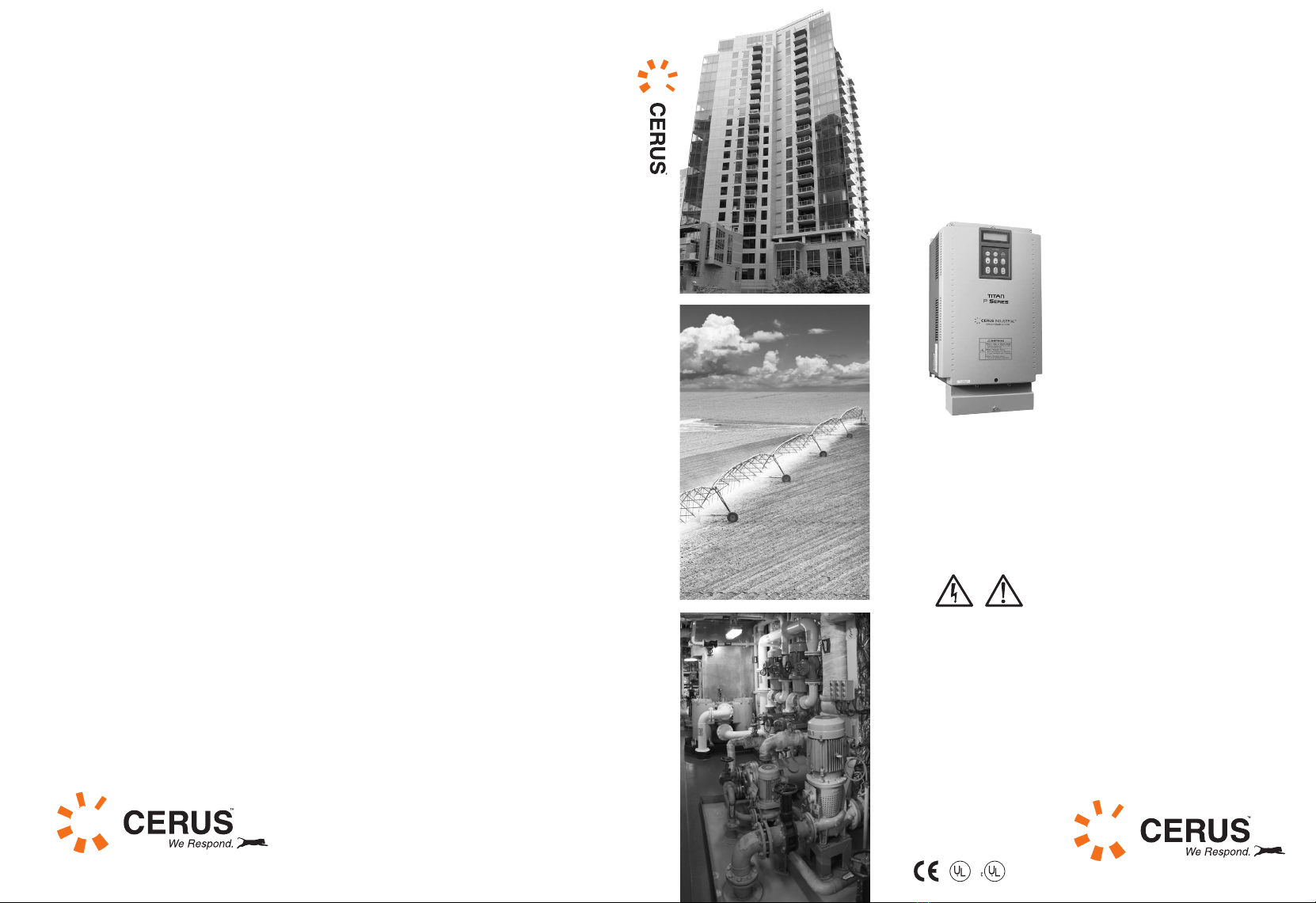
CHAPTER 2 - SPECIFICATION..........................................................................................................2-1
2.1 200~230V CLASS 7.5~40HP (5.5~30KW).............................................................................................2-1
2.2 380~480V CLASS 7.5~40HP (5.5~30KW).............................................................................................2-2
2.3 525~600V CLASS 7.5~40HP (5.5~30KW).............................................................................................2-2
2.4 380 ~480V CLASS 50~125HP (37~90KW) ...........................................................................................2-3
2.5 525~600V CLASS 50~150HP (37~110KW)...........................................................................................2-3
2.6 380 ~480V CLASS 150~700HP (110~525KW) .....................................................................................2-4
2.7 COMMON SPECIFICATIONS..................................................................................................................2-4
2.8 DIMENSIONS.........................................................................................................................................2-6
CHAPTER 3 - INSTALLATION AND WIRING .................................................................................3-1
3.1 INSTALLATION PRECAUTIONS .............................................................................................................3-1
3.2 BASIC WIRING DIAGRAMS...................................................................................................................3-2
3.3 CONTROL CIRCUITS WIRING ..............................................................................................................3-9
CHAPTER 4 - OPERATION.................................................................................................................4-1
4.1 VFD PROGRAMMING KEYPAD ............................................................................................................4-1
4.2 CONTROL MODES ................................................................................................................................4-4
4.3 FUNCTION SETTINGS AND DESCRIPTIONS ...........................................................................................4-5
4.4 CONTROL WIRING CONFIGURATIONS.................................................................................................4-8
CHAPTER 5 - PARAMETER LIST......................................................................................................5-1
5.1 [SET] SETUP PARAMETER GROUP ......................................................................................................5-1
5.2 [SET] PARAMETER GROUP DEFAULT SETTINGS ................................................................................5-3
5.3 [DRV] DRIVE PARAMETER GROUP ......................................................................................................5-5
5.4 [DRV] PARAMETER GROUP DEFAULT SETTINGS ...............................................................................5-6
5.5 [FG1] FUNCTION GROUP 1PARAMETER GROUP .................................................................................5-7
5.6 [FG1] PARAMETER GROUP DEFAULT SETTINGS ................................................................................5-8
5.7 [FG2] FUNCTION GROUP 2PARAMETER GROUP ...............................................................................5-10
5.8 [FG2] PARAMETER GROUP DEFAULT SETTINGS ..............................................................................5-12
5.9 [I/O] INPUTS/OUTPUTS PARAMETER GROUP .....................................................................................5-13
5.10 [I/O] PARAMETER GROUP DEFAULT SETTINGS ..............................................................................5-17
5.11 [APP] APPLICATION PARAMETER GROUP .......................................................................................5-19
5.12 [APP] PARAMETER GROUP DEFAULT SETTINGS ............................................................................5-21
5.13 [EXT] EXTENSION PARAMETER GROUP ..........................................................................................5-22
5.14 [EXT] PARAMETER GROUP DEFAULT SETTINGS............................................................................5-22
5.15 [COM] COMMUNICATION PARAMETER GROUP ..............................................................................5-22
5.16 [COM] PARAMETER GROUP DEFAULT SETTINGS ..........................................................................5-24
CHAPTER 6 - PARAMETER DESCRIPTION....................................................................................6-1
6.1 SETUP GROUP [SET] ............................................................................................................................6-1
6.2 DRIVE GROUP [DRV] ........................................................................................................................6-10
6.3 FUNCTION GROUP 1[FG1] ................................................................................................................6-12
6.4 FUNCTION GROUP 2[FG2] ................................................................................................................6-18
6.5 INPUT/OUTPUT GROUP [I/O] .............................................................................................................6-23
6.6 APPLICATION GROUP [APP] .............................................................................................................6-33
6.7 EXTENSION GROUP [EXT].................................................................................................................6-37
6.8 COMMUNICATION GROUP [COM].....................................................................................................6-38

vi
CHAPTER 7 - PID CONTROL WIRING AND BLOCK DIAGRAM.................................................7-1
7.1 VFD WIRING FOR PID CONTROL........................................................................................................7-1
7.2 PID CONTROL BLOCK DIAGRAM ........................................................................................................7-1
7.3 PID CONTROL SLEEP MODE WITH SLEEP PRESSURE BOOST FUNCTION DIAGRAM. ...........................7-2
7.4 PID CONTROL WITH PIPE BROKEN FUNCTION DIAGRAM. ..................................................................7-3
7.5 PID CONTROL WITH PRE-PID FUNCTION DIAGRAM. ..........................................................................7-4
7.6 PID CONTROL SETTING NOTES: .........................................................................................................7-5
CHAPTER 8 - TROUBLESHOOTING & MAINTENANCE ..............................................................8-1
8.1 FAULT DISPLAY ...................................................................................................................................8-1
8.2 FAULT REMEDY ...................................................................................................................................8-2
8.3 TROUBLESHOOTING ............................................................................................................................8-3
8.4 CHECKING VFD POWER COMPONENTS..............................................................................................8-3
8.5 MAINTENANCE.....................................................................................................................................8-5
CHAPTER 9 - OPTIONS.......................................................................................................................9-1
9.1 OPTION LIST ........................................................................................................................................9-1
9.2 REMOTE KEYPAD CABLE ....................................................................................................................9-1
9.3 DBU (DYNAMIC BRAKING UNIT)SIZES...............................................................................................9-1
9.4 DBU AND DBR TERMINALS AND WIRING ............................................................................................9-1
9.5 THE BASIC WRING DIAGRAM FOR DYNAMIC BRAKING UNIT AND RESISTOR. ....................................9-2
9.6 DBU FRAME 1DIMENSIONS.................................................................................................................9-3
9.7 DBU FRAME 2DIMENSIONS.................................................................................................................9-4
9.8 DBU FRAME 3DIMENSIONS.................................................................................................................9-5
9.9 DYNAMIC BRAKING RESISTOR SIZING ................................................................................................9-6
9.10 NEMA TYPE 1OPTIONAL CONDUIT BOX........................................................................................9-6
CHAPTER 10 - MODBUS-RTU COMMUNICATION........................................................................10-1
10.1 INTRODUCTION ................................................................................................................................10-1
10.2 SPECIFICATION ................................................................................................................................10-1
10.3 COMMUNICATION PARAMETERS.....................................................................................................10-2
10.4 MODBUS-RTU COMMUNICATION PROTOCOL.................................................................................10-2
10.5 PARAMETER CODE LIST ...................................................................................................................10-3
CHAPTER 11 - APPENDIX “A”- UL MARKING................................................................................. VI
11.1 SHORT CIRCUIT INTERRUPTING RATING ........................................................................................... VI
11.2 BRANCH PROTECTION FUSES OR CIRCUIT BREAKER SIZING ............................................................ VI
11.3 TERMINAL SCREWS,TORQUE AND WIRE GAUGE ............................................................................. VII
CHAPTER 12 - CONFORMATION, STANDARDS AND WARRANTY.......................................... VIII

Chapter1 – Basic Information
1-1
CHAPTER 1 - BASIC INFORMATION
1.1 Part Number Code and Initial Inspection
The VFD part numbering system is shown below.
CI- 007- P 2 NE
Horse power rating N: No Keypad
O: UL Open Type
E: UL Enclosed Type 1
L: Built-in DC Choke
007 7.5 HP
VFD Series Input Voltage
P 2 200 - 230V
4 380 - 480V
6 525 - 600V
- Remove VFD from its packing and inspect its exterior for shipping damage. If there is damage, notify
the shipping agent and your CERUS sales representative.
- Remove the VFD cover and inspect VFD for any damage or foreign objects. Check VFD part number,
HP rating and nominal voltage on the sticker attached to the side of the VFD. Verify if VFD electrical
and environmental ratings are correct and adequate for the application.

Chapter 1 – Basic information
1.2 Basic configuration
The following devices are required to operate VFD. Proper peripheral devices must be selected and correct
connections made to ensure proper operation. An incorrectly applied or installed VFD can result in system
malfunction or reduction in product life as well as component damage. You must read and understand this
manual thoroughly before proceeding.
AC Power
Source
Use a power source with a voltage within the
permissible range of VFD input power rating.
MCCB Select circuit breakers or fuses in accordance with NEC
and applicable local codes.
Inline Magnetic
Contactor
Do not use input power contactor for frequent starting
and stopping the VFD, otherwise VFD power
components can be damaged.
AC Line Reactor
or Harmonic
Filter
The line reactor provides some degree of surge
protection and decreases a level of harmonic distortion
in power line. It is recommended to use it when power
source kVA rating is more than 10 times higher than
VFD rating. The Harmonic filter provides higher level
of harmonic mitigation.
EMI/ RFI Filter
Install EMI/RFI filter to decrease VFD Electromagnetic
and Radio Frequency Interference with operation of
sensitive electronic equipment.
Variable
Frequency Drive
Install VFD with proper orientation, ventilation,
spacing etc. according to the manufacturer
requirements with all necessary protective and filtering
devices to provide long and reliable VFD operation.
AC Load
Reactor or
Output Filter
In order to protect a motor winding install a load
reactor for motors 380VAC and above with distance to
the motor greater than 45 feet or output filter for more
than 100 feet. Install an output filter for 200-230VAC
motors if distance is greater than 200 feet.
Three Phase AC
Induction Motor
Opening the motor circuit by disconnect or contactor
during VFD run can damage VFD power components.

Chapter2 – Basic Information
2-1
CHAPTER 2 - SPECIFICATION
The P-Series VFDs can be used in phase conversion (single-phase input power and three-phase output at the
same voltage) applications. The below tables contain VFD ratings for three-phase and phase-conversion
variable torque applications. In order for Cerus to maintain warranty on VFD for phase conversion
applications, the customer should call Cerus with application information and line reactor installation is
required. Refer to page 3-7 for power wiring description.
2.1 200~230V Class 7.5~40HP (5.5~30kW)
Part Number (CI-xxx-P2) & UL Type
(U1-Type 1, UO-Open Type)
007
U1
010
U1
015
U1
020
U1(6)
025
U1(6)
030
U1(6)
040
U1(6)
Standard Duty Variable Torque
Motor Rating (1)
HP (1) 7.5 10 15 20 25 30 40
kW 5.5 7.5 11 15 18.5 22 30
FLA[A] 24 32 46 60 74 88 115
Heavy Duty Variable Torque or
Standard Duty Constant Torque
Motor Rating (1)
HP (1) 5 7.5 10 15 20 25 30
kW 3.7 5.5 7.5 11 15 18.5 22
FLA[A] 17 23 33 44 54 68 84
Output ratings
Capacity [kVA] 9.1 12.2 17.5 22.9 28.2 33.5 43.8
Voltage (2) 3φ200 ~ 230 VAC
Frequency 0.01 ~ 120 Hz
Input ratings Voltage (5) 3φ200 (-15%) ~ 230 VAC (+10 %)
Frequency 50/60 Hz (±5 %)
Weight kg
(lbs.) 4.9
(
11
)
6
(
13.2
)
6
(
13.2
)
13
(
29
)
13.5
(
30
)
20
(
44.1
)
20
(
44.1
)
VFD Ratings for Phase Conversion Application
Single-Phase Input Viltage [V] 1φ200 ~ 230 VAC
Single-Phase Input Current
[
A
]
24 32 46 60 74 88 115
VFD Output Current [A] 12 16 24 32
37
46 60

Chapter 2 - Specification
2-2
2.2 380~480V Class 7.5~40HP (5.5~30kW)
2.3 525~600V Class 7.5~40HP (5.5~30kW)
Part Number (CI-xxx-P4) & UL Type
(U1-Type 1, UO-Open Type)
007
U1
010
U1
015
U1
020
U1(6)
025
U1(6)
030
U1(6)
040
U1(6)
Standard Duty Variable Torque
Motor Rating (1)
HP (1) 7.5 10 15 20 25 30 40
kW 5.5 7.5 11 15 18.5 22 30
FLA[A] 12 16 24 30 39 45 61
Heavy Duty Variable Torque or
Standard Duty Constant Torque
Motor Rating (1)
HP (1) 5 7.5 10 15 20 25 30
kW 3.7 5.5 7.5 11 15 18.5 22
FLA[A] 8 11 17 22 28 34 44
Output ratings
Capacity [kVA] 9.6 12.7 19.1 23.9 31.1 35.9 48.6
Voltage (2) 3φ380 ~ 480 VAC
Frequency 0.01 ~ 120 Hz
Input ratings Voltage (5) 3φ380 (-15%) ~ 480 VAC (+10 %)
Frequency 50/60 Hz (±5 %)
Weight kg
(lbs.)
4.9
(11)
6
(
13.2
)
6
(
13.2
)
12.5
(
28
)
13
(
29
)
20
(
44.1
)
20
(
44.1
)
VFD Ratings for Phase Conversion Application
Single-Phase Input Viltage [V] 1φ380 ~ 480 VAC
Single-Phase Input Current
[
A
]
12 16 24 30 39 45 61
VFD Output Current
[
A
]
6
8
12
16
19
24
30
Part Number (CI-xxx-P6) & UL Type
(U1-Type 1, UO-Open Type)
007
U1
010
U1
015
U1
020
U1(6)
025
U1(6)
030
U1(6)
040
U1(6)
Standard Duty Variable Torque
Motor Rating (1)
HP (1) 7.5 10 15 20 25 30 40
kW 5.5 7.5 11 15 18.5 22 30
FLA[A] 9 12 17 23 27 34 43
Heavy Duty Variable Torque or
Standard Duty Constant Torque
Motor Rating (1)
HP (1) 5 7.5 10 15 20 25 30
kW 3.7 5.5 7.5 11 15 18.5 22
FLA[A] 6.1 9 12 17 23 27 34
Output ratings
Capacity [kVA] 9.6 12.7 19.1 23.9 31.1 35.9 48.6
Voltage (2) 3φ525 ~ 600 VAC
Frequency 0.01 ~ 120 Hz
Input ratings Voltage (5) 3φ525 (-10%) ~ 600 VAC (+10 %)
Frequency 50/60 Hz (±5 %)
Weight kg
(lbs.)
6.5
(14.4)
7
(
15.5
)
7
(
15.5
)
12
(
26
)
12
(
26
)
19
(
42
)
19
(
42
)

Chapter 2 – Specification
2-3
2.4 380 ~ 480V Class 50~125HP (37~90kW)
Part Number (CI-xxx-P4) & UL Type
(U1-Type 1, UO-Open Type)
050
U1(6)
060
U1(6)
075
U1(6)
100
U1(6)
125
U1(6)
Standard Duty Variable Torque
Motor Rating (1)
HP (1) 50 60 75 100 125
kW 37 45 55 75 90
FLA[A] 75 91 110 152 183
Heavy Duty Variable Torque or Standard
Duty Constant Torque
Motor Rating (1)
HP (1) 40 50 60 75 100
kW 30 37 45 55 75
FLA[A] 55 75 91 110 152
Output ratings
Capacity [kVA] 59.8 72.5 87.6 121.1 145.8
Voltage (2) 3φ380 ~ 480 VAC
Frequency 0.01 ~ 120 Hz
Input ratings Voltage (5) 3φ380 (-15%) ~ 480 VAC (+10 %)
Frequency 50/60 Hz (±5 %)
Weight kg
(lbs.)
27
(60)
27
(60)
29
(
64
)
42
(
93
)
43
(
95
)
VFD Ratings for Phase Conversion Application
Single-Phase Input Viltage [V] 1φ380 ~ 480 VAC
Single-Phase Input Current [A] 75 91 110 152 183
VFD Output Current [A] 39 45 55 75
91
2.5 525~600V Class 50~150HP (37~110kW)
Part Number (CI-xxx-P6) & UL Type
(U1-Type 1, UO-Open Type)
050
U1(6)
060
U1(6)
075
U1(6)
100
U1(6)
125
U1(6)
150
U1(6)
Standard Duty Variable Torque
Motor Rating (1)
HP (1) 50 60 75 100 125 150
kW 37 45 55 75 90 110
FLA[A] 55 64 80 104 128 150
Heavy Duty Variable Torque or
Standard Duty Constant Torque
Motor Rating (1)
HP (1) 40 50 60 75 100 125
kW 30 37 45 55 75 90
FLA[A] 43 55 64 80 104 128
Output ratings
Capacity [kVA] 59.8 72.5 87.6 121.1 145.8 178
Voltage (2) 3φ525 ~ 600 VAC
Frequency 0.01 ~ 120 Hz
Input ratings Voltage (5) 3φ525 (-15%) ~ 600 VAC (+10 %)
Frequency 50/60 Hz (±5 %)
Weight kg
(lbs.)
32
(71)
32
(71)
32
(71)
46
(
102
)
46
(
102
)
101
(223)

Chapter 2 - Specification
2-4
2.6 380 ~ 480V Class 150~700HP (110~525kW)
2.7 Common Specifications
Cooling method Forced air cooling by internal fans
Short Circuit Rating 65kA, suitable for use on a circuit capable of delivering not more than 65,000
RMS Symmetrical Short Circuit Amperes
Agency Approvals UL and cUL listed, CE marked
CONTROL
Control Method V/F, Slip Compensation, Sensorless Vector w/auto tune (no encoder required)
Frequency Setting
Resolution
Digital Reference: 0.01 Hz (Below 100 Hz), 0.1 Hz (Over 100 Hz)
Analog Reference: 0.01 Hz / 60 Hz
Frequency Accuracy Digital: 0.01 % of Max. Output Frequency
Analog: 0.1 % of Max. Output Frequency
V/F Control Curve Linear, S-Pattern, User Defined Pattern
Overload Capacity 110 % per 1 min variable torque
150% per 1 min constant torque (20% de-rated VFD)
Torque Boost Manual Torque Boost Adjustment (0 ~ 15 %), Auto Torque Boost
OPERATION
Operation Method Keypad / Terminals / Communication
Frequency Setting Analog: 0 ~ 10VDC, ±10VDC, 4 ~ 20mA / Pulse Frequency / Ext-PID
Digital: Keypad
Input Signals
Start Signal Forward or Reverse
Multi-Step Up to 18 Speeds can be set including Jog (Use binary coded combinations of
Programmable Digital Inputs)
Multi Step
Accel/Decel Time
0.1~ 6,000 sec, Max 4 types can be set via Multi- Function Terminals. Accel/Decel
Pattern: Linear, U-Curve or S-Curve
Part Number (CI-xxx-P4) & UL Type (U1-Type 1,
UO-Open Type)
150
UO
200
UO
250
UO
350
UO
400
UO
500
UO
600
UO
700
UO
Standard Duty Variable Torque
Motor Rating (1)
HP (1) 150 200 250 350 400 500 600 700
kW 110 132 160 220 280 375 450 525
FLA[A]
223 264 325 432 547 613 731 877
Heavy Duty Variable Torque or
Standard Duty Constant Torque
Motor Rating (1)
HP (1) 125 150 200 250 350 400 500 600
kW 90 110 132 160 220 280 375 375
FLA[A] 183 223 264 325 432 547 613 731
Output ratings
Capacity [kVA] 178 210 259 344 436 488 582 699
Voltage (2) 3φ380 ~ 480 VAC
Frequency 0.01 ~ 120 Hz
Input ratings Voltage (5) 3φ380 (-15%) ~ 480 VAC (+10 %)
Frequency 50/60 Hz (±5 %)
Weight kg
(lbs.)
101
(223)
101
(223)
114
(252)
200
(442)
200
(442)
243
(536)
380
(837)
380
(837)
VFD Ratings for Phase Conversion Application
Single-Phase Input Viltage [V] 1φ380 ~ 480 VAC
Single-Phase Input Current [A] 223 264 325 432 547 613 731 877
VFD Output Current [A] 110 152 183 223
264
x x x

Chapter 2 – Specification
2-5
Emergency Stop Immediately Interrupts the VFD Output in any control method
Jog Jog Operation with adjustable Jog frequency
Fault Reset Resets VFD. Some critical faults can only be reset by recycling the VFD power.
Output signals
Four Multi-
Function Relays
Each relay can be set to Frequency Detection Level, Overload Alarm, Stalling,
Over Voltage, Low Voltage, VFD Overheating/ Running/ Stopping/ At Speed
, VFD
By-Pass, Speed Search etc.
Fault Output Double Throw Relay Contact (3A, 3C, 3B) – 1A up to 250VAC or 30VDC
Two Analog
Outputs
Selections: Output Frequency, Output Current, Output Voltage, Output kW, DC
Link Voltage. Both outputs are 0-10VDC scalable from 10 to 200%.
Operation Functions
DC Braking, Frequency Limit, Jump Frequencies, 2nd
Function, Slip Compensation,
Reverse Rotation Prevention, Auto Restart, Auto-Tuning, PID Control, Flying
Start, Safety Stop, Flux Braking, Low leakage, Pre-PID, Dual-PID, MMC(4), Motor
Pre-heat.
PROTECTION
VFD Fault Trips
Over Voltage, Low Voltage, Over Current, Overload Protection, Short Circuit
Protection, Ground Fault, VFD Overheat, Motor Overheat, Output Phase Open,
External Trip, CPU Communication Error, Loss of Speed Command, Hardware
Fault, etc.
VFD Alarm Stall Prevention, Overload Alarm, Thermal Sensor Fault
DISPLAY
Keypad
Operation
Information
Output Frequency, Output Current, Output Voltage, Frequency Set Value,
Operating Speed, DC Voltage, kWattmeter, Run-time, Last Trip Time
Fault History The VFD stores 5 last faults with Hz, A, VFD mode and trip time for each fault.
ENVIRONMENT
Ambient Temperature 14°F~ 104
(-10
~ 40
). De-rate VFD by 20% to increase rating up to 122
Storage Temperature -4°F~ 149
(-20
~ 65
)
Ambient Humidity Up to 95 % RH. (Non-Condensing)
Altitude Max. 3,300ft (1,000m). De-rate VFD 20% for every additional 1000ft.
Vibration Max. 0.6g (5.9m/sec2)
Environmental
Conditions
Pollution degree 2. No Corrosive Gas, Combustible Gas, Oil Mist or Dust
Notes:
1) Standard duty VT motor rating based on a 110% overload for 1 minute. Heavy-duty VT or Standard Duty CT
motor ratings based on 150% overload for 1 minute. The motor horsepower ratings are based on VFD nominal
voltage and 4-pole motor design. Operation at lower input voltages or motors with six or more motor poles
may require to upsize the drive depending on actual motor FLA rating.
2) Output voltage cannot exceed the input voltage. An output voltage should be programmed in the range from
input voltage to a minimum of the VFD voltage rating.
3) The standard conduit box attachment adds 1.8kg (4 lbs.), as minimum, to the weight of the drive.
4) MMC (Multi Motor Control) function is not available for 150HP and above VFDs.
5) De-rate VFD by 50% when the single-phase power will be applied to the VFD.
6) UL Open Type VFD with installed UL Type 1 kit.

Chapter 2 - Specification
2-6
2.8 Dimensions
1) CI-007-P2/4 (200/400V Class) and CI-007~015-P6 (600V Class)
inches (mm)
Model W1 W2 H1 H2 D1 C1 C2 C3 Enclosure Type
CI-007-P2/4 5.91
(150)
5.12
(130)
11.18
(284)
10.69
(269)
6.16
(156.5)
0.98
(24)
0.98
(24)
0.98
(24)
UL Type 1
IP20
CI-007~15-P6
7.87
(200)
7.09
(180)
13.98
(355)
13.39
(340)
7.19
(182.5)
1.12
(28.5)
0.94
(24)
1.12
(28.5)
UL Type 1
IP20

Chapter 2 – Specification
2-7
2) CI-010~015-P2/4 (200/400V Class)
inches (mm)
Model W1 W2 W3 H1 H2 D1 C1 C2 C3 Enclosure Type
CI-010~015-P2/4 7.87
(200)
7.09
(180)
0.23
(6)
11.18
(284)
10.69
(269)
7.16
(182)
1.37
(35)
0.98
(24)
1.37
(35)
UL Type 1
IP20

Chapter 2 - Specification
2-8
3) CI-020~040-P2/4 (UL Open Type with installed UL Type 1 kit) and
CI-020~040-P6 (UL Open Type)
inches (mm)
Model W1 W2 W3 H1 H2 H3 D1 D2
Enclosure
Type
CI
-
020
-
P2/4
CI-020-P6
9.84
(250)
9.06
(230)
7.9
(200.8)
15.16
(385)
14.57
(370)
17.88
(454.2)
7.91
(201)
5.74
(146)
UL Type 1
IP20
CI
-
025
-
P2/4
CI
-
025
-
P6
9.84
(250)
9.06
(230)
7.9
(200.8)
15.16
(385)
14.57
(370)
17.88
(454.2)
7.91
(201)
5.74
(146)
UL Type 1
IP20
CI
-
030
-
P2/4
CI
-
030
-
P6
11.97
(
304
)
11.18
(
284
)
9
.
29
(
2
36
)
18.11
(
460
)
17.52
(
445
)
23.59
(
599
.2
)
9.21
(
234
)
6.98
(
177.5
)
UL Type 1
IP20
CI
-
040
-
P2/4
CI
-
040
-
P6
11.97
(304)
11.18
(284)
9
.
29
(2
36
)
18.11
(460)
17.52
(445)
23.59
(599.2)
9.21
(234)
6.98
(177.5)
UL Type 1
IP20

Chapter 2 – Specification
2-9
4) CI-050~075-P4/6 (UL Open Type 400V and 600V VFDs with installed UL Type 1 kit)
inches (mm)
Model W1 W2 W3 H1 H2 D1 D2
Enclosure
Type
CI-050~060-P4
11.81
(
300
)
7.48
(
190
)
0.35
(
9
)
25.28
(
642
)
20.28
(
515
)
10.46
(
265.6
)
6.43
(
163.4
)
UL Type 1
IP20
CI
-
075
-
P4
CI-050~075-P6
11.81
(300)
7.48
(190)
0.35
(9)
25.28
(642)
20.28
(515)
11.52
(292.6)
7.5
(190.4)
UL Type 1
IP20

Chapter 2 - Specification
2-10
5) CI-100, 125-P4/6 (UL Open Type VFD with installed UL Type 1 kit)
inches (mm)
Model W1 W2 W3 H1 H2 D1 D2 Enclosure
Type
CI-100~125-P4/6 14.57
(370)
8.66
(220)
0.35
(9)
30.22
(767.5)
23.09
(586.5)
13.29
(337.6)
8.8
(223.4)
UL Type 1
IP20

Chapter 2 – Specification
2-11
6) CI-150~250-P4 & CI-150-P6 (UL Open Type VFDs)
inches (mm)
Model W1 W2 W3 W4 H1 H2 D1 Enclosure
Type
CI-150~200-P4
CI-150-P6
20.08
(510)
15.00
(381)
0.43
(11)
13.78
(350)
30.87
(784)
29.92
(760)
16.64
(422.6)
UL Open
IP00
CI-250-P4 20.08
(510)
15.00
(381)
0.43
(11)
13.78
(350)
33.90
(861)
33.00
(838)
16.64
(422.6)
UL Open
IP00
This manual suits for next models
40
Table of contents
Popular DC Drive manuals by other brands

Lenze
Lenze i510 Series Mounting and switch-on instructions

Rexnord
Rexnord Falk CT Series Operation and maintenance

Wittenstein Alpha
Wittenstein Alpha LK Series operating manual

Smartrise
Smartrise HPV900-INDUCTION Startup manual

ABB
ABB ACS355 series installation guide

lumishore
lumishore SUPRA SY225 Installation and operating instructions