Cervelo S5 User manual

S5 DISC MANUAL

1
Introduction..................................... 1
Frame Features................................... 2
Handlebar & Stem Components...................... 3
Handlebar Components - Stack..................... 4
Handlebar Components - Pitch Adjust.............. 5
Fork & Headset Components........................ 6
Small Parts...................................... 7
Frame Preparation................................ 8
S5 Disc Assembly Overview........................ 9
Before You Build................................ 11
Electric Cable Preparation...................... 12
Mechanical Cable Preparation.................... 13
Brake Housing Routing........................... 14
Electric Cable Routing.......................... 16
Mechanical Cable Routing........................ 17
Fork Installation............................... 18
Fork Topper Installation................................19
Stem Installation.......................................20
Stack Adjustment........................................21
Stem Fixing Screw Guide.................................22
Handlebar Installation..................................23
Handlebar & Stem - Electric Cable Routing ............24
Handlebar & Stem - Mechanical Cable Routing.............25
Di2 Battery Installation................................26
Electric Cable Installation.............................27
Mechanical Cable Installation...........................28
Seatpost Assembly.......................................29
Seatpost Cutting Instructions...........................30
Frame Protection Installation...........................31
Tire Clearance..........................................32
Rapid Axle Wheel Installation...........................33
Version 1 - 2018-07-31
TABLE OF CONTENTS
This manual is intended to assist Cervélo retailers in setting up and customizing the
2019 S5 Disc bicycle.This manual is not intended for consumer use, and requires the
use of the specied tools to ensure proper assembly. This manual also references
proprietary parts available only to retailers through direct ordering from Cervélo.
Failure to use the specied parts and to follow the supplied assembly instructions
may result in a loss of control while riding and serious injury.This manual is an
overview of the steps required to assemble this bicycle and to make any desired
modications as set forth in this manual. This manual assumes that the retailer has
the minimum required background and skill level required of all professional bicycle
mechanics. See https://www.probma.org/
IMPORTANT INFORMATION
NOTE: Cervélo strongly recommends that
all assembly and adjustment procedures
be performed by an authorized Cervélo
retailer.If you are a Cervélo S5 Disc
consumer/purchaser reading this manual we
suggest that before attempting to undertake
any of the procedures in this manual
that you consult your authorized Cervélo
retailer, or visit us at
www.cervelo.com/support
2
This manual outlines a number of procedures for
making optional adjustments to the S5 Disc which
dier from the way the bicycle is originally sold
by Cervélo.The following tools and parts listed
are required for these adjustments.These parts
are not available for consumer purchase and are
only available for purchase by Cervélo retailers.
Cervélo strongly recommends that all assembly
and adjustment procedures be performed by an
authorized Cervélo retailer.
All parts available for separate purchase are noted
in this manual with Cervélo part numbers listed in
ALL- CAPS FORMAT, with a full listing provided
on page 3.These parts are available by visiting the
Cervelo Customer Portal https://dealers.cervelo.com
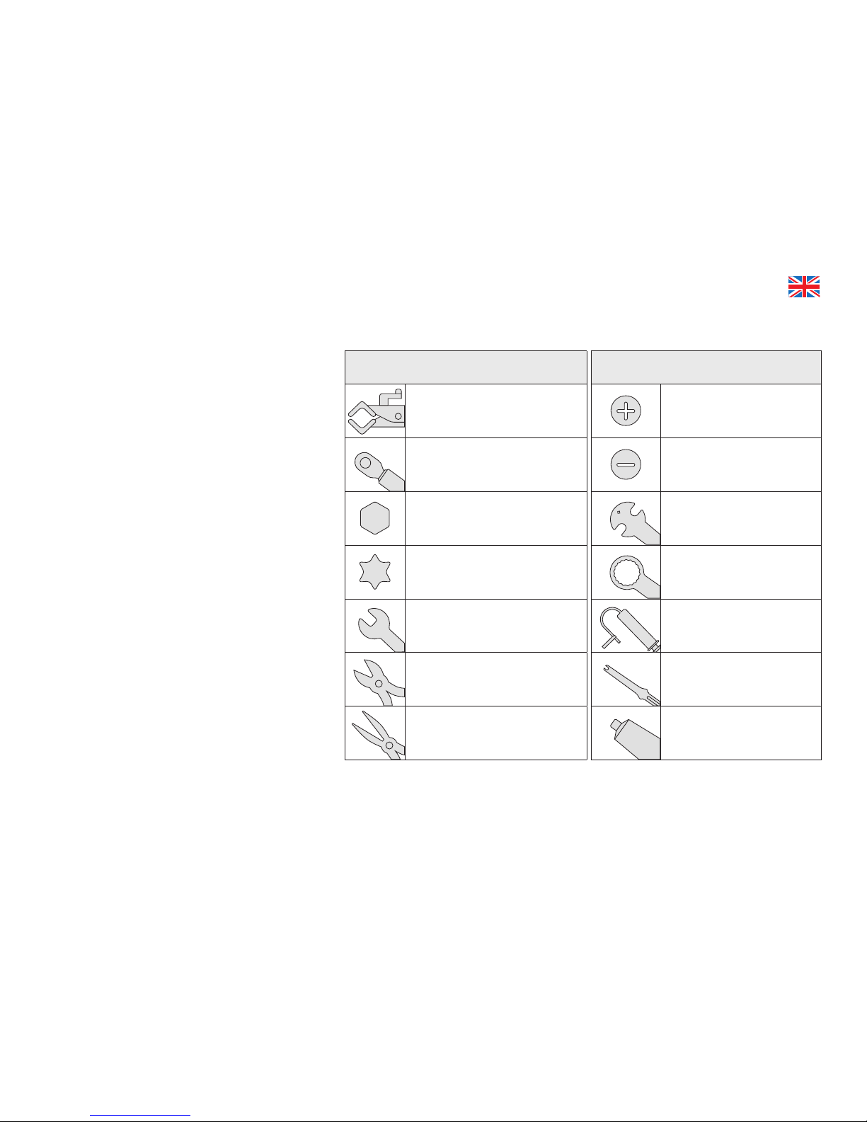
LIST OF TOOLS & SUPPLIES
NOTE: All non-proprietary components
such as those from Shimano or SRAM are
available from your local distributor.
NOTE: This manual was developed to
compliment the Cervelo General User
Manual, and is intended as a supplement
to the assembly and installation
instructions supplied by the component
manufacturers (provided with this
bicycle).
Tools
Bicycle workstand (types which
secure bike by the seatpost, or
pro-type stand with fork mount)
Torque wrench(es) with 2.5Nm
to 15Nm range and adaptors:
Allen (Hex) head inserts:
2mm, 2.5mm, 3mm, 4mm,
5mm, 6mm, 8mm, 10mm
Torx head inserts:T25
Open ended wrenches:
7mm, 8mm, 10mm, 17mm
Cable cutters
Pliers
Tools
Philips-head screwdriver
Slot-head screwdriver
Pedal wrench
Brake rotor lockring tools
Hydraulic bleed kit
Di2 wire tool – Shimano
Good quality bicycle grease

3
2019 S5 DISC PARTS LIST
Item Description Cervélo Part No.
S5 Stack Adjustment
Dealer Kit KP-0E0S5
Conventional 1 1/8"
Stem Adapter FKA-FK60-1125
Computer Mount
Adapter Plate MT-AB08-CAP
M6X1.0X14 CS028
BOLT KIT BT-C028-14
M6X1.0X20 CS028
BOLT KIT BT-C028-20
M6X1.0X25 CS028
BOLT KIT BT-C028-25
M6X1.0X30 CS028
BOLT KIT BT-C028-30
M6X1.0X35 CS028
BOLT KIT BT-C028-35
M6X1.0X40 CS028
BOLT KIT BT-C028-40
M6X1.0X45 CS028
BOLT KIT BT-C028-45
Aftermarket FK60 Fork
Assembly Kit 48 FKA-FK60-SM
Aftermarket FK60 Fork
Assembly Kit 51 FKA-FK60-MD
Item Description Cervélo Part No.
Aftermarket FK60 Fork
Assembly Kit 54-58 FKA-FK60-LG
CS028 Stem 80mm w/
Plugs ST-CS028-80
CS028 Stem 90mm w/
Plugs ST-CS028-90
CS028 Stem 100mm w/
Plugs ST-CS028-100
CS028 Stem 110mm w/
Plugs ST-CS028-110
CS028 Stem 120mm w/
Plugs ST-CS028-120
CS028 Stem 130mm w/
Plugs ST-CS028-130
AB08 Mounting Kit
0mm HBP-AB08-ZERO
AB08 Mounting Kit
2.5mm HBP-AB08-2.5MM
AB08 Mounting Kit 2.5
Degrees HBP-AB08-2.5DEG
AB08 Mounting Kit 5
Degrees HBP-AB08-5DEG
AB08 Carbon
Handlebar 380mm HB-AB08-38
Item Description Cervélo Part No.
AB08 Carbon
Handlebar 400mm HB-AB08-40
AB08 Carbon
Handlebar 420mm HB-AB08-42
AB08 Carbon
Handlebar 440mm HB-AB08-44
SP20 Carbon Post
0mm Oset w/Head SP-SP20-ZERO
SP20 Carbon Post
25mm Oset w/Head SP-SP20-25MM
Seat Post Clamp
Assembly 0E0 S5 SPC-0E0S5
Internal Battery
Mount Assembly 0E0 MT-BINT
BB Cable Guide/Cover
0E0 BBG-0E0
Chainstay Protector
0E0 S Series PRO-CS-S
Disc Brake Hose
Guide CBG-DBH
ST28 Spacer Kit
30mm SS-C028-KIT
Front Der Mount for
0E0 S5 w/Rivets FDM-0E0S5

4
A guide to your Cervélo S5 Disc frame.
Rear Dropout Cable Exit
Front Derailleur Wire
Exit Hole, electric
and mechanical
Bottom Bracket Cable Port
Internal Di2 Battery
Mount Holes
FRAME FEATURES

5
HANDLEBAR & STEM COMPONENTS
Cervélo AB08
Handlebar
Cervélo CS28 Stem
38cm HB-AB08-38
40cm HB-AB08-40
42cm HB-AB08-42
44cm HB-AB08-44
5mm Stem Spacers x6
SS-C028-KIT
M6 Stem Fixing Screws
(Sets of 3)
0mm Stack BT-C028-14
5mm Stack BT-C028-20
10mm Stack BT-C028-25
15mm Stack BT-C028-30
20mm Stack BT-C028-35
25mm Stack BT-C028-40
30mm Stack BT-C028-45
Stem Cap* (Rear)
Stem Cap* (Front)
80mm ST-CS28-80
90mm ST-CS28-90
100mm ST-CS28-100
110mm ST-CS28-110
120mm ST-CS28-120
130mm ST-CS28-130
*Stem Caps are
included with stem
WARNING
Only use the components
speci ed in this manual for
handlebar and stem assembly.
Failure to use the speci ed
parts and to follow the supplied
assembly instructions may result
in a loss of control while riding
and serious injury.

0˚
0˚
+2.5mm
6
HANDLEBAR COMPONENTS – STACK
- Handlebar Fixing
Nuts (L + R) for
0mm stack
- M5 x 14mm Bolts (x4)
- Handlebar Fixing Nuts (L + R)
for 2.5mm stack
- 2.5mm Bar Spacers (L + R)
- M5 x 16mm Bolts (x4)
0mm Stack Kit
2.5mm Stack Kit
Bar Fixing Screw
M5 x 14mm
Actual Size
Bar Fixing Screw
M5 x 16mm
Actual Size
14mm
16mm
The AB08 handlebar stack can be increased by 2.5mm or
rotated in increments of 2.5˚ or 5˚ by the use of specic
Stack or Pitch Adjust Wedge kits.
WARNING
All handlebar mounting parts are
clearly labeled for proper installation.
Mixing parts will void warranty and
may result in injury.
HBP-AB08-2.5MM
HBP-AB08-ZERO

2.5˚
5˚
7
HANDLEBAR COMPONENTS – PITCH ADJUST
- Handlebar Fixing Nut
(L + R) for 2.5˚ rotation
- 2.5˚ Pitch Adjust Wedge (L + R)
- M5 x 16mm Bolts (x4)
- Handlebar Fixing Nuts (L + R)
for 5˚ rotation
- 5˚ Pitch Adjust Wedge (L + R)
- M5 x 16mm Bolts (x4)
2.5˚ Pitch Adjust Kit
5˚ Pitch Adjust Kit
WARNING
Handlebar Pitch Adjust Wedges
are not designed to be used in
conjunction with Handlebar Stack
spacers.
Bar Fixing Screw
M5 x 16mm
Actual Size
16mm
HBP-AB08-2.5DEG
HBP-AB08-5DEG

8
FORK & HEADSET COMPONENTS
WARNING
Your Cervélo frame & fork have
been designed to work together.
Do not attempt to install an
alternative fork.
Preload Cone
Fork Topper
Top Bearing
Dust Seal
Fork Topper
Fixing Screws x4
M5 x 16
Top Bearing
1", 36° x 45°
Bottom Bearing
1-3/8", 36° x 45°
Preload Cone
Fixing Screw
M6 x 18mm
NOTE: The S5 Disc headset
assembly does not require
a compression ring.
Fit Top Bearing Dust
Seal to Fork Topper
before installation.
FK60 Fork
Assembly Kit
FKA-FK60-SM
FKA-FK60-MD
FKA-FK60-LG

9
Front Fork Axle Insert
QRI-RAT
Internal Battery Mount Kit
MT-BINT
BB Cable
Guide/Cover
BBG-0E0
Front Derailleur
Wire Hole Blanking
Plug
GR-ST-CLOSED
Disc Hose Bushing x2
CBG-DBH
Seatpost Clamp
SPC-0E0S5
Computer Mount
Adaptor Plate
MT-AB08-CAP
Rear Derailleur
Hanger Assembly
DRH-RAT
Rear Derailleur
Press-In Cable
Stop (Mechanical)
CBS-DRPOUT
Rear Derailleur
Wire Guide
(Electric)
GR-DRPOUT-GUIDE
Rear Derailleur
Blanking Plug
(Wireless)
GR-DRPOUT-CLOSED
Designed to accommodate electronic, mechanical and hydraulic controls, the S5 Disc frame
is engineered to provide seamless integration of all shifting systems, regardless of method or
brand. In order to do so, you will require the parts shown below:
SMALL PARTS

10
FRAME PREPARATION
1. Apply carbon paste to both frame and seatpost.
2. Insert Seatpost Clamp (SPC-0E0S5).
3. Adjust height and torque to 8Nm maximum.
Clamping the top tube can
damage the frame and void
your warranty.
Hold the frame using a
secured seatpost only.
Lightly grease Rear Derailleur Hanger Fixing
Nut and install Rear Derailleur Hanger
(DRH-RAT for Cervélo Rapid Axle) nger
tight. Final tightening will be done after rear
wheel installation.
Do not nal tighten rear derailleur hanger
assembly without rear wheel installed.
Doing so will result in a misaligned
derailleur and poor shifting.
Lightly grease supplied M4 xing screw,
and install the Front Fork Axle Insert (QRI-
RAT for Cervélo Rapid Axle) to the fork.
Tighten to 3Nm.

11
S5 DISC ASSEMBLY OVERVIEW
Prepare the frame by installing the rear brake
hose and derailleur controls, exiting the frame
through the upper surface of the headtube. Do
not trim.
Attach the rear brake caliper. Derailleur control
wires can either be attached at this point, or
remain exposed through the Bottom Bracket
Cable Port.
Prepare the fork by installing the brake hose
from the lower leg hose passage, exiting
through the top of the leading edge of the fork.
Attach the front brake caliper.
Prepare the handlebar by installing the shift/
brake levers.
For Di2 builds, prepare the stem, by routing
the 750mm length E-Wire so it passes
through both blades, with the connector
ends exposed at the handlebar end of each
port.
01
NOTE: See the following pages for more detailed assembly instructions.
02
03
04
05
06

12
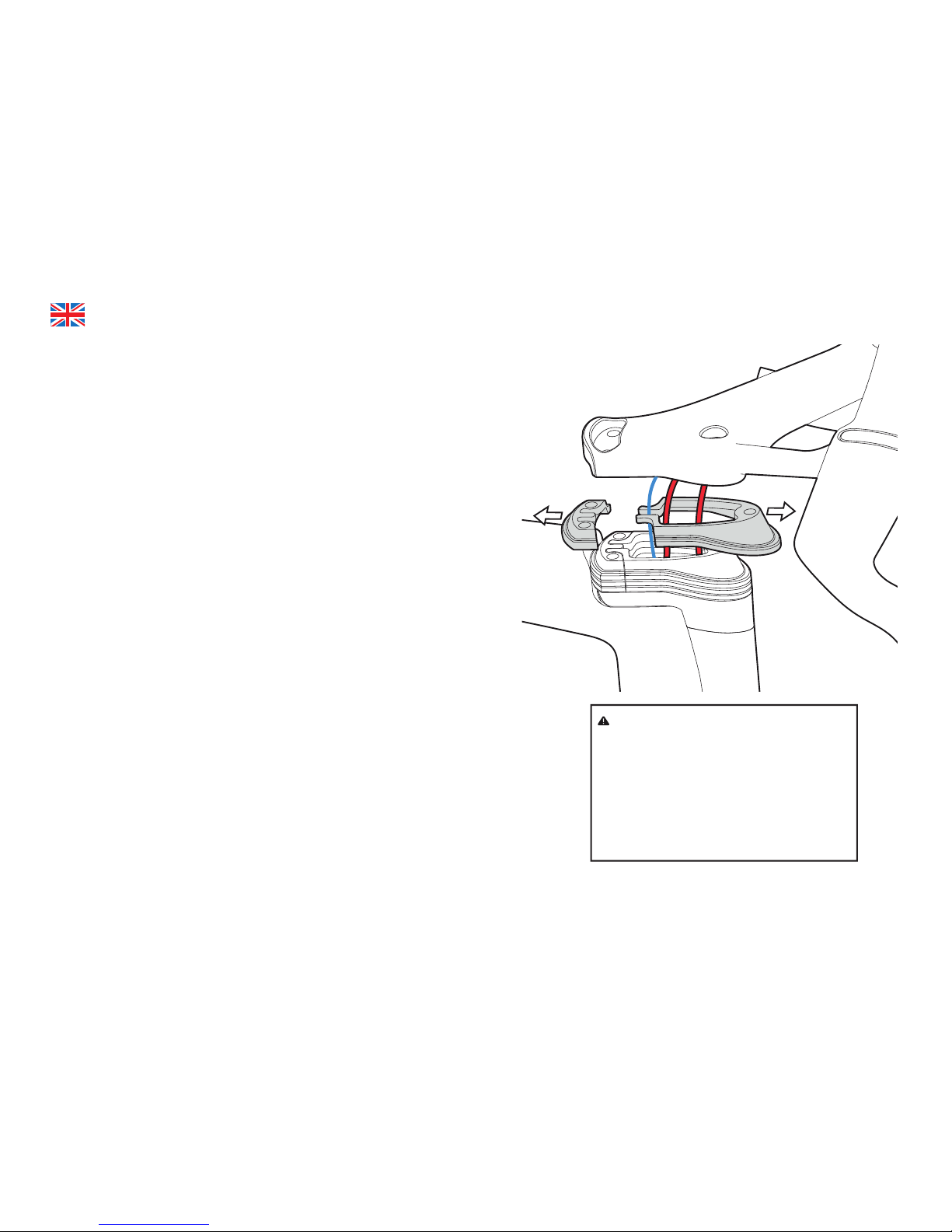
Grease the bearing cups in the frame, then
install bearings. Feed brake hose and
derailleur controls through Preload Cone.
Install fork and tighten Preload Cone until fork
has no play but still rotates smoothly. Refer to
page 20.
Feed hoses and derailleur controls through Fork
Topper. Use the supplied M5 x 16mm screws to
secure fork. Refer to page 21.
Feed cables and hoses through desired
amount of 5mm Stem Spacers.
Install the stem so that the brake hoses
pass through the appropriate blades. E-Wire
travels up through the right hand blade. With
mechanical controls the rear housing is on the
right and the front on the left.
Ensure you have the correct length bolts,
apply Loctite 242 and secure the stem and
stem spacers to the ForkTopper. Refer to
pages 22-24.
Install handlebar and connect the controls.
Refer to page 25
07
08
09
10
11
12
13
• While the two-piece 5mm Stem Spacers allow for addition/removal without
re-cabling the bike, the length of the cables used during rst assembly will
dictate how much adjustment is possible later on.
• After rst assembly it is simpler to remove Stem Spacers (go lower) and
trim the hydraulic brake hose at the brake lever as required.
• Adding spacers after rst assembly (go higher) may require replacement of
the cables to get the required length.
• Whenever possible, it is best to establish the correct t before performing
nal cabling of the S5.
Here are a few tricks that we have learned along the way that may help with
reinstallation:
Before reinstalling the stem with no spacers:
• Loosen the handlebar xing screws a few turns.
• In order to avoid pinching the rear brake hose during reinstallation of the
stem, simply remove the rear brake caliper from the frame and draw the
extra hose length out, by gently pulling the caliper toward the rear of the
bike.
• Taking care not to kink the derailleur housing (if using mechanical), carefully
reinstall the stem by feeding the extra hoses into the frame, and tighten the
stem xing bolts to 7Nm.
• Reinstall the rear brake caliper by pushing the extra housing into the frame.
• Ensure the hoses and housings are located in the appropriate slot in the
bar, and tighten the handlebar xing bolts to 5Nm.
BEFORE YOU BUILD
WARNING
Do not attempt to force hydraulic brake
hose that will not slide smoothly into
the frame through the fork topper/
head tube. This may result in the
cables becoming kinked or cracked,
and cause a uid leak which can result
in a loss of brake function and a risk of
serious injury.
14
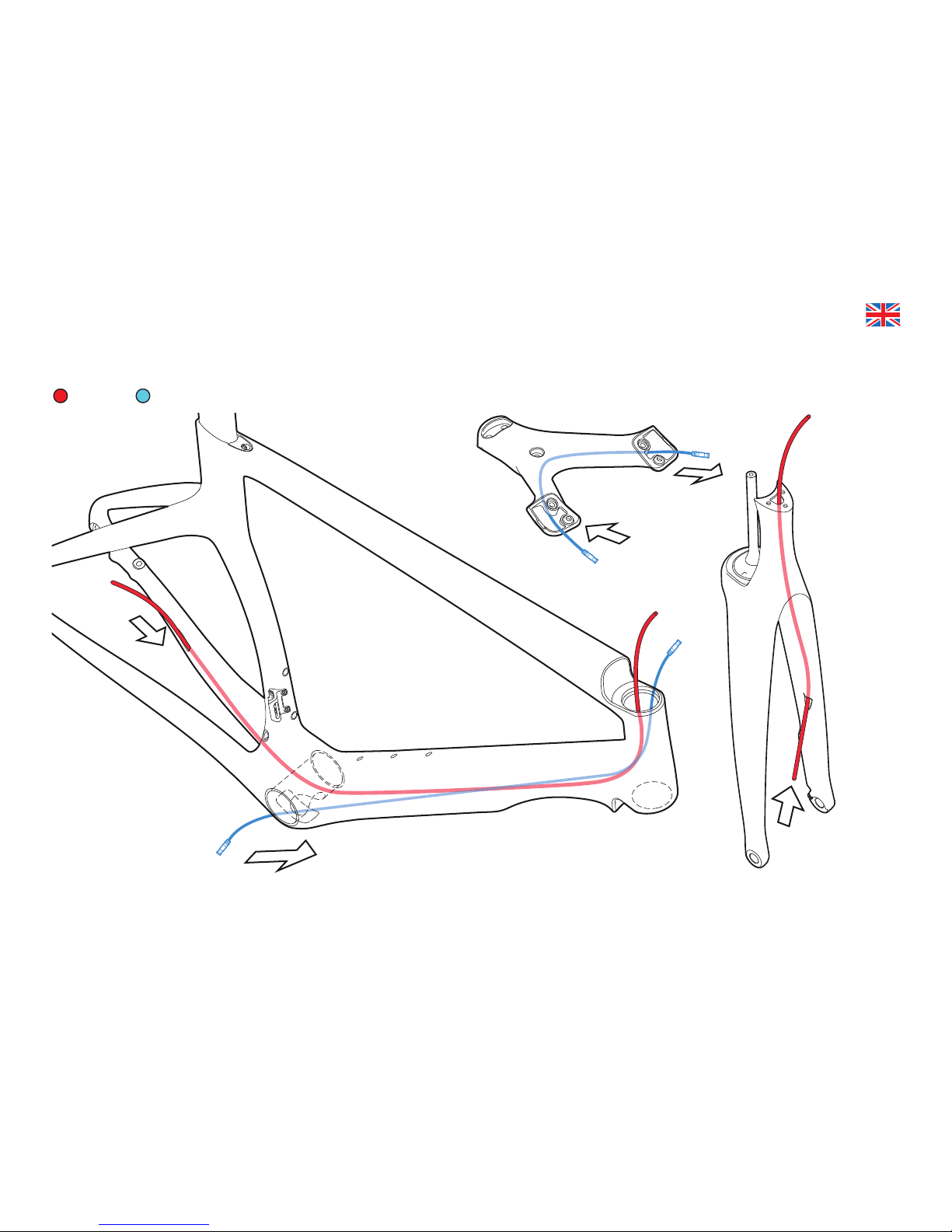
ELECTRIC CABLE PREPARATION
Run 750mm Di2
E-Wire cable
through stem
blades.
Run brake
hose from
bottom of
fork up
through top.
Route 1400mm Di2
E-Wire cable from
bottom bracket
through headtube.
Route
brake hose
from chainstay
through head tube.
Brake E-Wire

15
MECHANICAL CABLE PREPARATION
Run brake hose
from bottom of
fork up through
top.
Route shifter
housing from
bottom bracket
through headtube.
Route
brake hose
from chainstay
through head tube.
Brake E-Wire Front Shifter

16
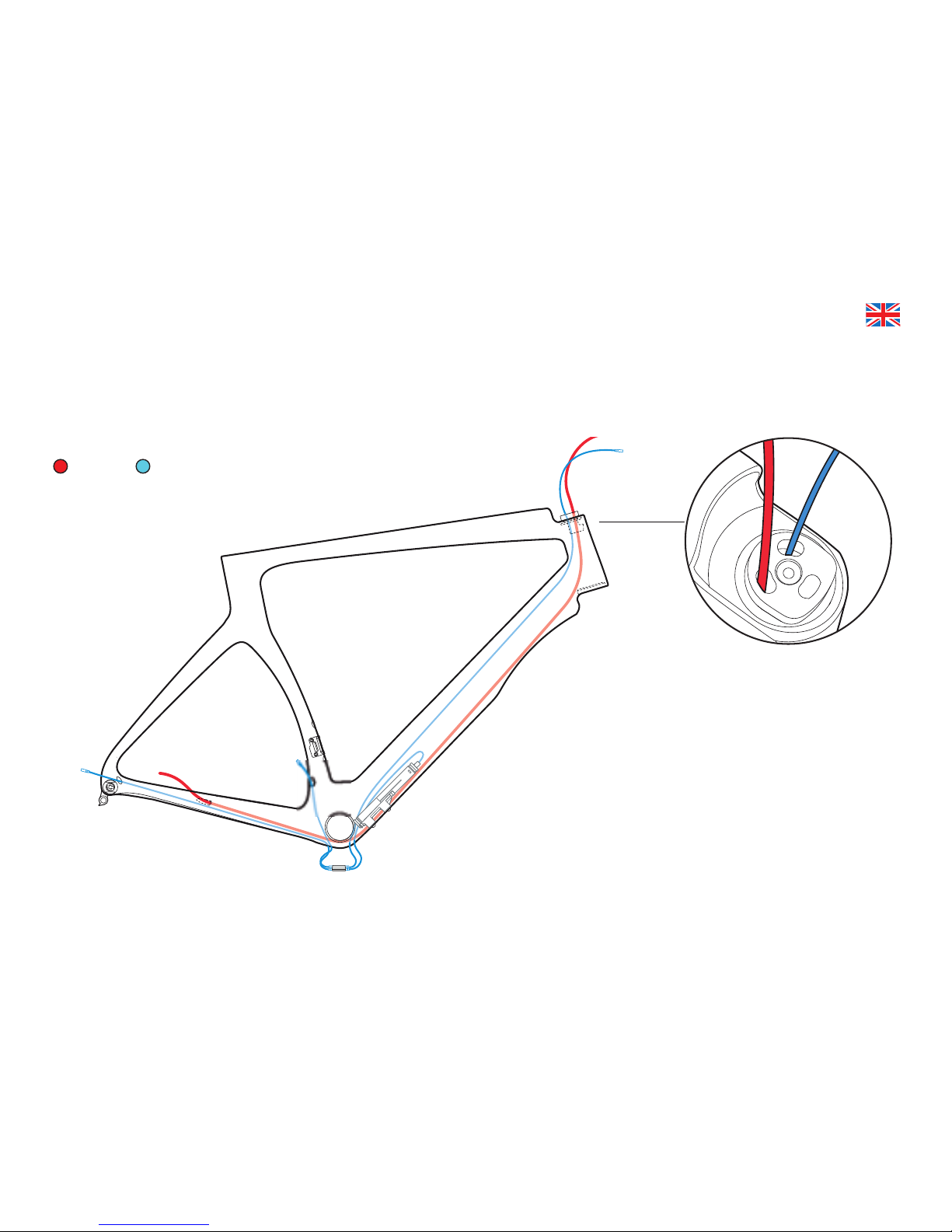
Electric: Route rear brake
hose through the right
Preload Cone pass-through.
Mechanical: Route rear brake
hose through the front Preload
Cone pass-through.
It is recommended that the hydraulic brake hoses or brake cable housing is installed rst. These
routing illustrations are intended as a supplement to the manufacturer’s installation instructions only.
For both hydraulic and mechanical disc brakes, please refer to the component manufacturer’s service
center or website for further information.
BRAKE HOUSING ROUTING

17
Route hydraulic brake hose or mechanical brake housing through the frame and fork with the Disc
Hose Bushings (CBG-DBH). Install and adjust calipers as per manufacturer’s instructions.
BRAKE HOUSING ROUTING
18
It is recommended that electric cabling and junction points be installed after
the brake hose has been installed.These routing illustrations are intended as a
supplement to the manufacturer’s installation instructions only. Please refer to the
component manufacturer’s service center or website for further information.
ELECTRIC CABLE ROUTING
Route rear brake hose
through the right Preload
Cone pass-through and Di2
E-Wire through the left.
Brake E-Wire

19
It is recommended that front and rear derailleur cables be installed after
the brake hose has been installed.These routing illustrations are intended
as a supplement to the manufacturer’s installation instructions only. Please
refer to the component manufacturer’s service center or website for further
information.
MECHANICAL CABLE ROUTING
Route gear cable housing
out of the Bottom
Bracket Cable Port.
Ensure that the housing
is not twisted together.
Add ferrules to the
bottom bracket end of
the housing.
Route rear brake hose through the
front Preload Cone pass-through.
Route the rear shifter cable
through the right and the front
shifter cable through the left.
Brake E-Wire Front Shifter
Other manuals for S5
4
Table of contents
Other Cervelo Bicycle manuals


