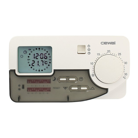
CEWAL PTE2.0 Operating manual

1 – PRESENTAZIONE
PTE2.0 è un c
ronotermostato elettronico da parete, a due temperature. Esso permette di
programmare in modo estremamente facile ed
immediato il riscaldamento ed il
condizionamento nell’arco della giornata in funzione del proprio stile di vita. Assicura il
confort desiderato unitamente alla migliore gestione dell’energia. PTE2.0 è stato progettato
per adattarsi a tutti i tipi di energia: gas, gasolio, elettricità.
2 – INSTALLAZIONE
Scelta della posizione
Ai fini di ottenere da PTE2.0 la migliore performance nel mantenimento della temperatura
desiderata, se ne consiglia l’installazione a circa ,5 mt
dal pavimento, su un muro interno,
al riparo dall’irradiazione diretta del sole e da ogni altra fonte di
calore diretta come ad
esempio lampade, stufe, radiatori,ecc.
Svitare la vite di fissaggio del corpo allo zoccolo.
Separare il corpo dallo zoccolo.
Passare i fili attraverso la finestra dello zoccolo e, utilizzando le viti e i tasselli in
dotazione, fissare lo zoccolo sulla scatola da incasso oppure direttamente alla parete.
Sganciare la parte mobile della morsettiera e fissare su di essa i due f
dell’impianto come da schema sotto riportato, cioè:
-
morsetti e 2 per utilizzatori di contatto diretto (stacca per aumento di
temperatura) come sono generalmente i riscaldatori
oppure:
-morsetti 2 e 3 per utilizzatori di contatto inverso, in
commutazione (stacca per
riduzione di temperatura) come sono generalmente i condizionatori
Riagganciare la parte mobile della morsettiera alla parte fissa
IMPORTANTE:
PER IL CORRETTO COLLEGAMENTO ELETTRICO
RISPETTARE LE INDICAZIONI DELLO SCHEMA
Riposizionare il corpo del cronotermostato sullo zoccolo e fissare la vite
IT
ronotermostato elettronico da parete, a due temperature. Esso permette di
immediato il riscaldamento ed il
condizionamento nell’arco della giornata in funzione del proprio stile di vita. Assicura il
confort desiderato unitamente alla migliore gestione dell’energia. PTE2.0 è stato progettato
Ai fini di ottenere da PTE2.0 la migliore performance nel mantenimento della temperatura
dal pavimento, su un muro interno,
calore diretta come ad
Passare i fili attraverso la finestra dello zoccolo e, utilizzando le viti e i tasselli in
dotazione, fissare lo zoccolo sulla scatola da incasso oppure direttamente alla parete.
Sganciare la parte mobile della morsettiera e fissare su di essa i due f
ili elettrici
morsetti e 2 per utilizzatori di contatto diretto (stacca per aumento di
commutazione (stacca per
riduzione di temperatura) come sono generalmente i condizionatori
.
Riposizionare il corpo del cronotermostato sullo zoccolo e fissare la vite
.
1 – PRESENTATION
PTE2.0
is an electronic, two temperatures,
and immediate daily
programming of your heating and air conditioning sys
individual lifestyles
. It guarantees the right comfort level and best energy savings.
has been designed to adapt to any sort of energy supply: gas, gas oil and electricity.
2 – INSTALLATION
Choosing the ight position
The best position for installing your
PTE2.0
wall protected from direct sunlight and any other source of direct heat, like lamps, ovens,
radiators, etc.
Unscrew the screw securing the
casing
Separate the casing from the base
.
Pass the wires through the opening in the base and use the supplied screws and
dowels to fix the base to the built-
in box or directly to the wall
Unhook the moving part of the terminal and fix on it the two electrical wires of the
system following
the diagram below
-
terminals and 2 for direct contact users (releases the contact when the
temperature increases) generally used for heaters
or:
-
terminals 2 and 3 for inverse contact users, switching contact, (releases the
contact when the temperature falls) generally used for air conditioning units
Hook the mobile part of the terminal to the fixed part.
IMPORTANT:
FOR THE CORRECT WIRING PLEASE
THE INDICATIONS GIVEN IN THE DIAGRAM
Replace the casing of the chronothermostat and tighten the screw
MANUALE INSTALLAZIONE E USO
CRONOTERMOSTATO PTE2.0
INSTALLATION AND
PTE2.0
CHRONOTHERMOSTAT
Disco per la regolazione dell'orario
Cavalieri per la programmazione
Manopola di regolazione. temperatura confort
Selettore del regime di funzionamento
Sportello di accesso alle pile
Manopola di regolazione temperatura ridotta
Tacca di riferimento dell'orario
is an electronic, two temperatures,
wall-mounting chronothermostat. It allows easy
programming of your heating and air conditioning sys
tem as to satisfy
. It guarantees the right comfort level and best energy savings.
PTE2.0
has been designed to adapt to any sort of energy supply: gas, gas oil and electricity.
PTE2.0
is at around .5 m from the floor, on an internal
wall protected from direct sunlight and any other source of direct heat, like lamps, ovens,
casing
to the base.
.
Pass the wires through the opening in the base and use the supplied screws and
in box or directly to the wall
.
Unhook the moving part of the terminal and fix on it the two electrical wires of the
the diagram below
:
terminals and 2 for direct contact users (releases the contact when the
temperature increases) generally used for heaters
terminals 2 and 3 for inverse contact users, switching contact, (releases the
contact when the temperature falls) generally used for air conditioning units
.
Hook the mobile part of the terminal to the fixed part.
FOR THE CORRECT WIRING PLEASE
FOLLOW
THE INDICATIONS GIVEN IN THE DIAGRAM
Replace the casing of the chronothermostat and tighten the screw
.
MANUALE INSTALLAZIONE E USO
CRONOTERMOSTATO PTE2.0
INSTALLATION AND
USE GUIDE
CHRONOTHERMOSTAT
Clock regulation disk
Programming sectors
Comfort temperature regulation knob
Operating regime selector
Battery compartment flap
Reduced temperature regulation knob
Time reference notch
EN

AVVERTENZA:
Se l’installazione del PTE2.0 viene effettuata in sostituzione di un p ecedente
te mostato con alimentazione a 220V, dov anno esse e utilizzati solo i due
condutto i elett ici dell’impianto che p ovengono dall’appa ecchio da comanda e. È
impo tante che i imanenti condutto i non utilizzati vengano accu atamente isolati.
3 – INSERIMENTO DELLE PILE
Dopo l’installazione dell’apparecchio, aprire lo sportello di accesso alle pile tirando
l’apposita linguella. Inserire due pile alcaline (importante!) formato stilo tipo LR6 rispettando
le polarità indicate nello schema riportato nel vano batterie.
4 – REGOLAZIONE DELL’ORA
Far girare il disco di regolazione in senso orario fino a far coincidere l’indicazione oraria
segnata sul disco con la tacca di riferimento .
5 – REGOLAZIONE DELLE TEMPERATURE
Si possono regolare due livelli di temperatura tra +6°C e +30°C.
Tempe atu a confo t:
È la temperatura che normalmente si desidera mantenere durante le ore di presenza in
casa. La temperatura comfort si regola posizionando l’indice della manopola in
corrispondenza della temperatura desiderata.
Tempe atu a idotta:
È la temperatura, normalmente più bassa di quella confort, abitualmente desiderata durante la
notte o durante le ore di assenza. La temperatura ridotta si regola posizionando l’indice della
manopola in corrispondenza della temperatura desiderata. Si consiglia di regolare la
temperatura ridotta a un valore di 3 - 5°C inferiore a quello della temperatura confort.
NOTA: la risposta dei relè alla programmazione fatta (click di scatto) avviene con un ritardo
di qualche decina di secondi.
6 – SCELTA DEL REGIME DI FUNZIONAMENTO
Il selettore permette di scegliere il regime di funzionamento:
Regime automatico: commutazione automatica tra le temperature confort e ridotta
secondo le fasce orarie programmate tramite l’orologio.
Regime confort permanente: mantiene il livello della temperatura confort selezionato
con la manopola .
Regime antigelo: permette di mantenere permanentemente una temperatura minima
di 4 °C durante le assenze prolungate. Questo protegge le tubature dell’abitazione dai
rischi del gelo. Per maggiore garanzia questa temperatura non è regolabile.
7 – PROGRAMMAZIONE DELL’OROLOGIO
L’orologio del PTE2.0 consente di programmare le fasce orarie corrispondenti alle
temperature confort e ridotta. La programmazione è estremamente agevole:
- posizionare i cavalieri verso l’esterno del disco per i periodi di temperatura confort
- posizionare i cavalieri verso l’interno del disco per i periodi di temperatura ridotta
La programmazione così effettuata rimarrà inalterata tutti i giorni purché il selettore sia
impostato sulla posizione orologio.
NOTA: l’impianto verrà attivato dal cronotermostato all’ora programmata. Sarà opportuno
quindi in fase di programmazione tener conto del tempo necessario all’impianto per portare
in temperatura l’ambiente.
8 – CARATTERISTICHE TECNICHE
-Campo di regolazione della temperatura confort e ridotta: da +6°C a +30°C
- Antigelo:+ 4°C
- Differenziale statico: 0,5°C
- Alimentazione: 2 pile alcaline tipo LR6 (formato stilo)
- Durata delle pile: circa un anno
- Uscita: contatto in commutazione senza potenziale
- Portata:
8A/250 VAC cos φ = (carico resistivo)
2A/250 VAC cos φ =0,6 (carico induttivo)
-Temperatura di funzionamento: da 0°C a +50°C
-Temperatura di stoccaggio: da – 0°C a +60°C
-Umidità: max 90% a 20°C
-IP30
-Raccordi con morsetti a vite:
Filo rigido fino a 2,5 mm
2
Filo flessibile fino a ,5 mm
2
9 – CONFORMITÀ ALLE NORME
-- EN 60730
-- BT 2006/95/CE
-- EMC 2004/ 08/CE
10 – PRESCRIZIONI DI SICUREZZA
Prima di collegare il cronotermostato accertarsi che la tensione di alimentazione del
CARICO UTILIZZATORE da comandare NON SIA
COLLEGATA. Verificare inoltre che il
carico sia compatibile con le caratteristiche di portata dei contatti (vedere dati tecnici).
ATTENZIONE: le operazioni di collegamento descritte nel presente foglio istruzioni vanno
eseguite esclusivamente da personale specializzato o dall’installatore, rispettando
scrupolosamente le norme di sicurezza e le disposizioni di legge vigenti.
WARNING:
If the PTE2.0 is eplacing a p evious the mostat with a 220V supply, just the two
elect ic leads coming f om the appliance to be cont olled must be connected. The
emaining leads, that a e no mo e used, must be ca efully isolated.
3 – FITTING THE BATTERIES
After installing the appliance, open the flap to the battery compartment by pulling the
tab. Fit in two alkaline batteries (important!) type LR6, respecting the polarity indicated
inside the battery compartment.
4 – REGULATING THE TIME ON THE CLOCK
Turn the regulation disk in a clockwise direction until the actual time, shown on the disk ,
matches with the time reference notch
.
5 – REGULATING THE TEMPERATURES
Two heating temperatures can be set between +6°C and +30°C.
Comfo t tempe atu e:
This is the temperature you normally want to have into the room when you are at home.
Use knob to regulate it to the desired level.
Reduced tempe atu e:
This is the temperature, usually lower than the comfort one, you normally want to have into
the room when you are not at home. Use knob to regulate it to the desired level.
We advise setting the reduced temperature 3 or 5°C lower than the comfort temperature.
NOTA: the response of the rela to the programming (audible click) comes with a dela of a
few tens of seconds.
6 – CHOOSING THE OPERATING REGIME
The selector allows choosing the operating regime:
Automatic: automatic switch over between comfort and reduced temperature
according to the programmed time bands on the clock.
Permanent comfort: keeps the comfort temperature set using knob .
Antifreeze: keeps a minimum permanent temperature of around 4°C during long
periods of absence. This protects the plumbing of the house against the risk of
freezing. For greater guarantee this temperature cannot be regulated.
7 – PROGRAMMING THE SECTORS ON THE CLOCK
The PTE2.0 clock allows programming time bands for comfort and reduced temperature.
Programming is extremely easy:
- place the sector towards the outside of the disk for comfort temperature periods
- place the sector towards the inside of the disk for reduced temperature periods
This program will then be repeated every day if the selection switch remains on the
clock position.
NOTE: the heating s stem will start working at the programmed time. Therefore we
recommend anticipating appropriatel the start and stop of the comfort period so that the
s stem reaches the desired temperature on time.
8 – TECHNICAL FEATURES
-Temperatures regulation range, comfort and reduced: from +6°C to +30°C
-Antifreeze: +4°C
-Static differential: 0,5°C
-Power supply: 2 AA batteries, type LR6
-Batteries life: approximately one year.
-Output: switch over contact without potential.
-Delivery:
8 A/250 VAC cos φ = (resistive load)
2 A/250 VAC cos φ =0,6 (inductive load)
-Working temperature: between 0°C and +50°C
-Storage temperature: between – 0°C and +60°C
-Humidity: max. 90% at 20°C
-IP30
-Joint with screwed terminals:
Stiff wire up to 2.5 mm
2
Flexible wire up to .5 mm
2
9 – CONFORMITY TO STANDARDS
-- EN 60730
-- BT 2006/95/CE
-- EMC 2004/ 08/CE
10 – SAFETY RECOMMENDATIONS
CHECK THAT THE POWER IS DISCONNECTED on the USER BEING CONTROLLED
before connecting the chronothermostat. Check that the power input is compatible with the
output on the contacts (see the technical data).
ATTENTION: only specialized electricians or authorized installers must carry out the
electric connection instructions given in this leaflet, in full observance of the safety
instructions and current applicable legislation.
X75428-
Other CEWAL Thermostat manuals
Popular Thermostat manuals by other brands

SOMFY
SOMFY Connected wired thermostat installation guide
Neptronic
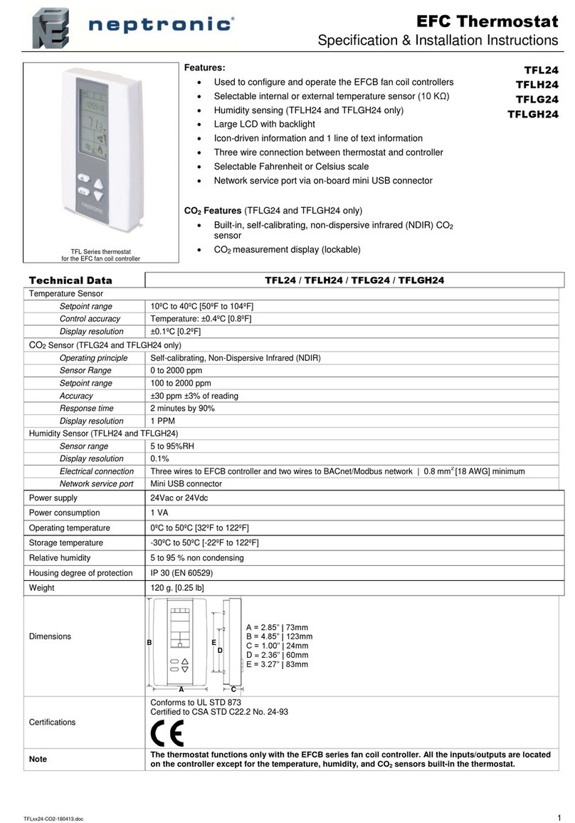
Neptronic EFC Specification & installation instructions

Neomitis
Neomitis RTE7D installation instructions
White Rodgers
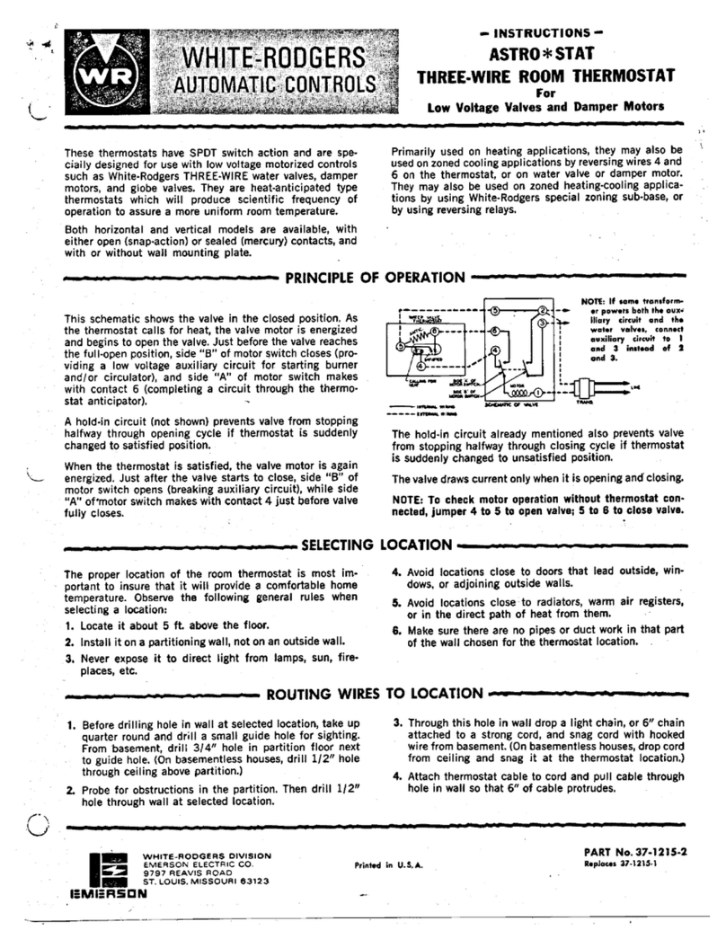
White Rodgers Astro Stat quick guide

Siemens
Siemens 5TG5930-1WH operating instructions
Sundirect
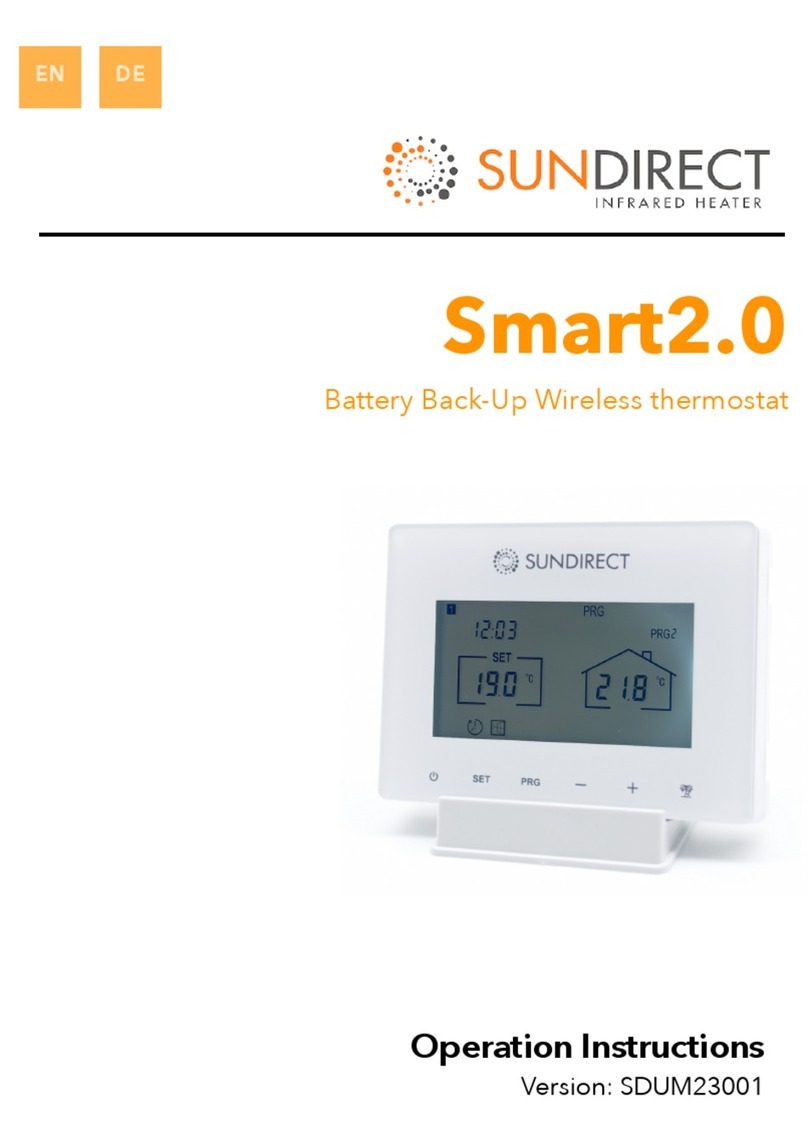
Sundirect Smart2.0 operating instructions
Daikin
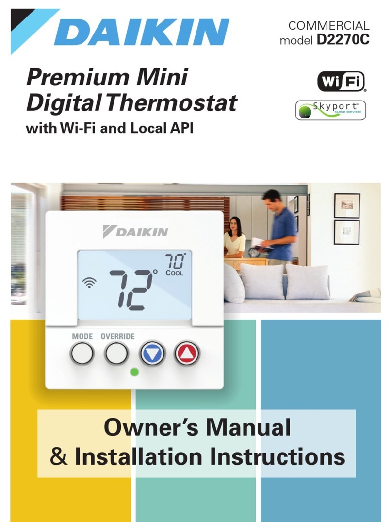
Daikin D2270C Owner's Manual & Installation Instructions
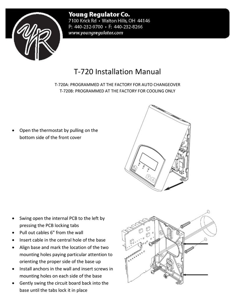
Young Regulator
Young Regulator T-720 Series installation manual
TRU Components
TRU Components TC-ZR011 operating instructions
Horstmann
Horstmann 425 Tiara User operating instructions

Pro1 Technologies
Pro1 Technologies T725 Operation manual
LUX
LUX T20-1141SA installation guide
