CF MOTO CF150T-6 User manual

All manuals and user guides at all-guides.com
all-guides.com
CF150T-6/CF150T-6A/CF125T-22/CF125T-22A is designed only for one driver and one passenger; the total
load must be within the limit specified on the specification label.
The scooter is designed only for on-road driving .
Pay special attention to all the sentences or paragraphs marked with WARNING in this manual.
As the manual is considered as indispensable, it should be always kept with the driver for consultation.
.
.
All manuals and user guides at all-guides.com
Thanks for choosing the scooter CF150T-6/ CF150T-6A/ CF125T-22/ CF125T-22A. For safer and more
pleasant driving, a complete understanding of all the instructions in this manual is necessary. Your safety is not
only ensured by your own alertness and your understanding of all operations but also related to your
understanding of the mechanic performance of the scooter. Making inspections before driving and performing
periodical maintenance are basic conditions for your safety.
When periodic maintenance or repair is necessary, please consult with your local dealer.
Wish you a pleasant drive.
The manufacturer reserves the rights to make improvement of the product at any time without prior notice
and without any obligation whatever.
All manuals and user guides at all-guides.com

All manuals and user guides at all-guides.com

All manuals and user guides at all-guides.com

A driver will always spend much time on learning driving methods and technique before driving on the
highway in less traffic area.
1. Many accidents occur due to that automobile driver cannot see the scooter driver. Therefore, the scooter
driver should make all his effort to be seen clearly by automobile driver.
For example: Wear noticeable clothing.
Avoid driving carelessly.
2. Many accidents occur at the crossroad entrance or exit of parking lot and driveway. Therefore pay
attention to the above places.
3. Over speed is one of the main causes for many scooter accidents. Please obey the traffic rules and drive
within the speed limit.
4. Many scooter accidents occur due to insufficient experience. A new driver shall comprehend each
performance of scooter before riding on the highway. Never lend scooter to inexperienced drivers.
5. Most injuries of scooter accidents are on head. Therefore please wear helmet and other protections, e.g.
dust-tight glasses, boots and thick coat.
6. Avoid driving on bump road, which will result in losing control or damaging machine.
All manuals and user guides at all-guides.com
all-guides.com
1. Before starting the engine, please carefully inspect the scooter. (Refer to Page 17).
2. For safety, please wear helmet as well as boots, gloves, dust-tight glasses and noticeable clothing;
3. The top box or cargo box mounted by customer himself is for lightweight stuff only. If cargo boxes are
mounted on both sides of scooters, please load equally on both and tight properly to avoid moving during driving.
For detail, refer to page 3;
4. When driving, please hold the handlebar with both hands and step on the decks;
5. Please exercise on road in less traffic area and be familiar with scooter performance before driving on the
roadway;
6. Turn on turning signal, when turning or changing lane.
7. Remember not to drive on the road shoulder. And please remember not to destroy natural scene and not
forget to cherish public property.
8. The run-in period of this scooter is 1500km. Max. Speed: 50km/h within 0~1000km, and 60km/h within
1000~1500km. Please avoid rapid acceleration, rapid deceleration or climbing long slope with heavy load.
Adjust and inspect the scooter, change engine oil and clean air cleaner according to maintenance interval. Fail to
operate in such process will reduce the performance and shorten the scooter life.
All manuals and user guides at all-guides.com
All manuals and user guides at all-guides.com
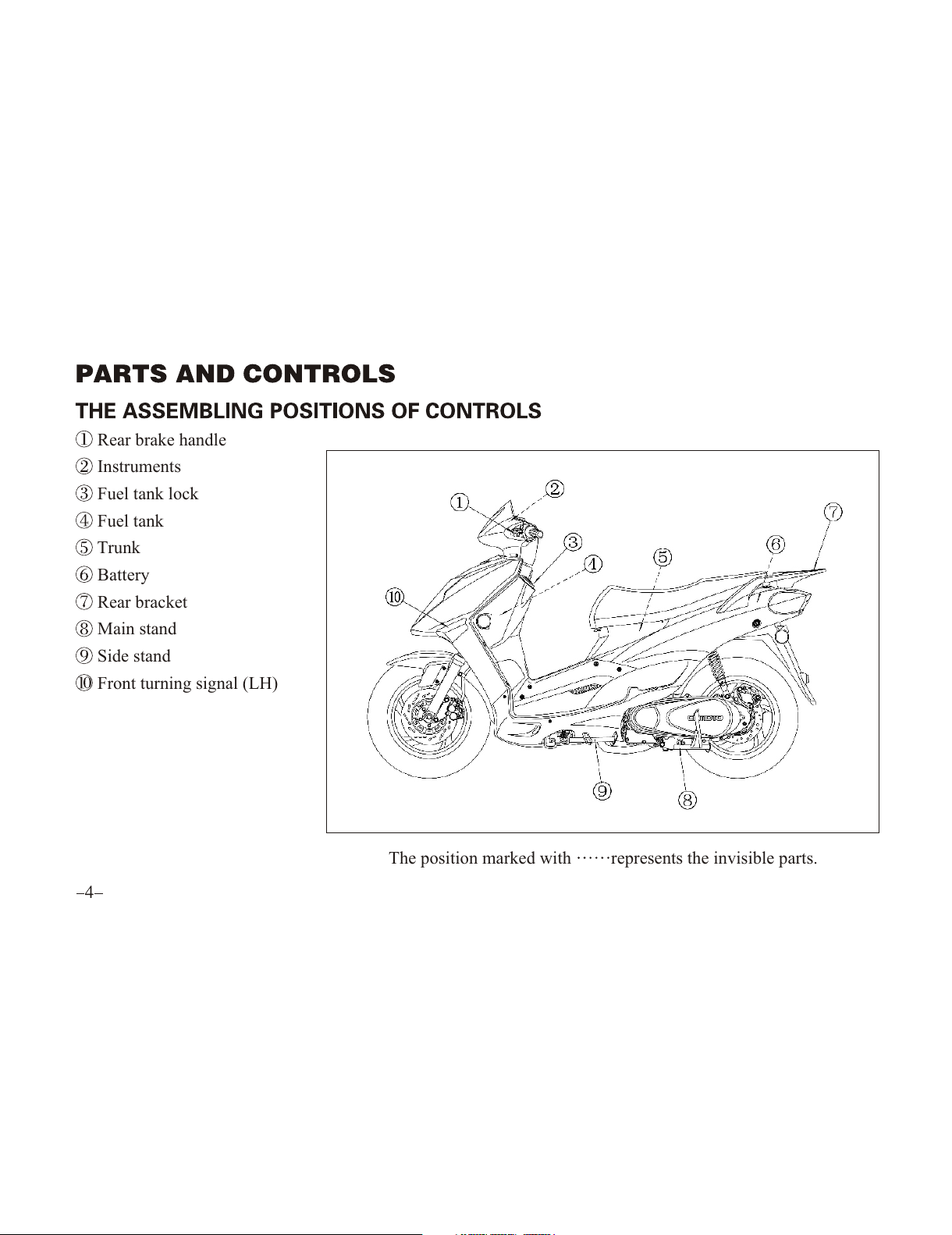
Rear brake handle
Instruments
Fuel tank lock
Fuel tank
Trunk
Battery
Rear bracket
Main stand
Side stand
Front turning signal (LH)
The position marked with represents the invisible parts.
All manuals and user guides at all-guides.com
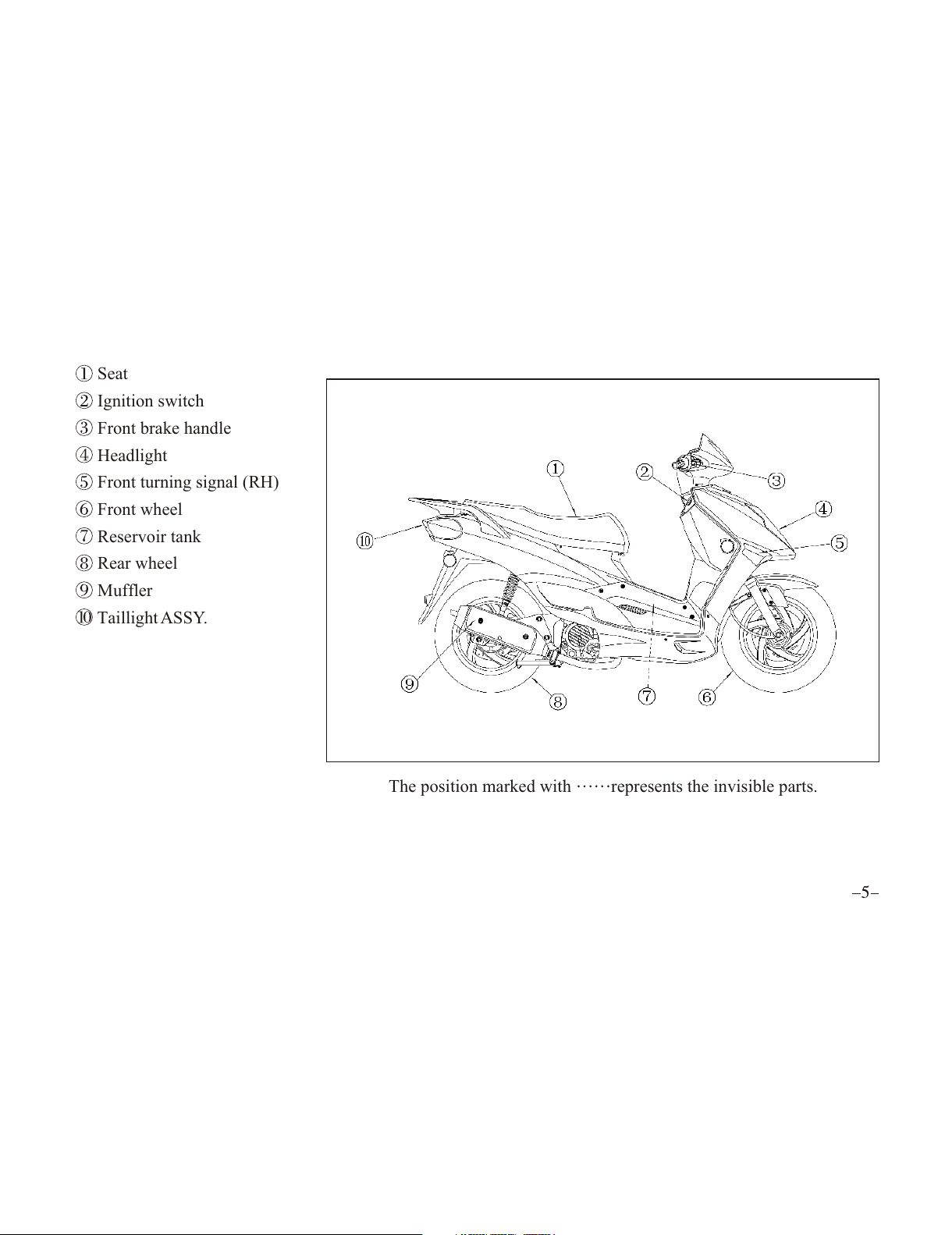
Seat
Ignition switch
Front brake handle
Headlight
Front turning signal (RH)
Front wheel
Reservoir tank
Rear wheel
Muffler
Taillight ASSY.
The position marked with represents the invisible parts.
All manuals and user guides at all-guides.com

Horn button
Turning switch
Turning reset switch
High/low beam switch
Kill switch
Night switch
Starting button
All manuals and user guides at all-guides.com
all-guides.com
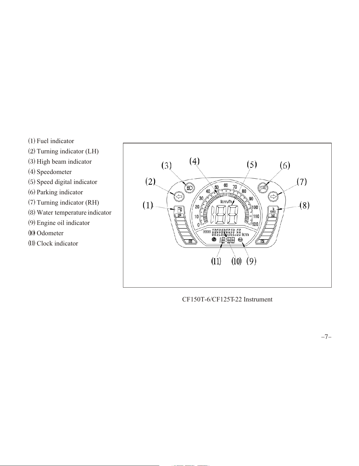
Fuel indicator
Turning indicator (LH)
High beam indicator
Speedometer
Speed digital indicator
Parking indicator
Turning indicator (RH)
Water temperature indicator
Engine oil indicator
Odometer
Clock indicator
CF150T-6/CF125T-22 Instrument
All manuals and user guides at all-guides.com

Fuel indicator
Turning indicator (LH)
High beam indicator
Speedometer
Speed digital indicator
Parking indicator
Turning indicator (RH)
Water temperature indicator
Engine oil indicator
Odometer
Clock indicator
Failure indicator
CF150T-6A/CF125T-22A Instrument
All manuals and user guides at all-guides.com

Insert the key into the main switch to turn: ON, OFF or LOCK.
1. ON when turning the switch to the power is on the
engine can be started and the key cannot be taken out.
2. OFF when turning the switch to the power is off the
engine will be shut down and the key can be taken out.
3. LOCK Turn the handlebar to the most left position, press
the key and turn to and then take out the key. The handlebar
cannot be moved and the engine and all lights cannot be turned on.
Temperature indicator is on the right side of the instrument
panel which indicates the water temperature. The green area of side C indicates that the temperature is normal,
while the red area of side H indicates that the temperature is high. In case the temperature is so high repeatedly,
please check the amount of the coolant when temperature is down, or check the cooling system at your dealer.
.
All manuals and user guides at all-guides.com
Fuel gauge is on the left side of the instrument panel which indicates the amount of the fuel in the fuel tank.
The location F indicates that the amount of the fuel is full, and the location E indicates that the amount of the
fuel will be used up, please refill immediately.
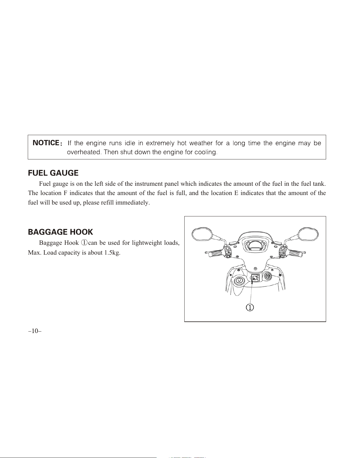
Baggage Hook can be used for lightweight loads,
Max. Load capacity is about 1.5kg.
All manuals and user guides at all-guides.com

CF150T-6A/CF125T-22A is equipped with fuel injection system. The failure indicator light is lower side of
instrument panel. When the light flashes, it indicates the ECU failure, refer to attached table for details. Failure
indicator light has two kinds of flash signals, long signal indicates tens digit , while short signal indicates
unit digit . Long signal flashes first and then the short signal. And one long signal mean 10, two long signals
means 20, and three long signals means 30. For example, when the error code is 23 , the failure indicator
light will flash two long signals first and then three short signals, after the failure indicator light is on.
ERROR TYPE
ERROR-TPS-LOW
ERROR-TPS-HIGH
ERROR-TH2O-LOW
ERROR-TH2O-HIGH
ERROR-TAir-LOW
ERROR-TAir- HIGH
ERROR-PAir-LOW
ERROR-PAir- HIGH
ERROR-VB-LOW
ERROR-VB- HIGH
FLASH
1
2
3
4
5
6
7
8
9
10
FAILURE DESCRIPTION
Incorrect lower position of throttle valve angle to be adjusted
Incorrect higher position of throttle valve angle to be adjusted
Earthing of water-temperature signal
Open or short circuit of water temperature to 5V
Earthing of air-temperature signal
Open or short circuit of air temperature to 5V
Open circuit of environmental air pressure sensor in ECU
Short circuit of ECU environmental air pressure sensor in ECU to 5V
Lower battery voltage, rectifier failure
Higher battery voltage, rectifier failure
All manuals and user guides at all-guides.com
all-guides.com
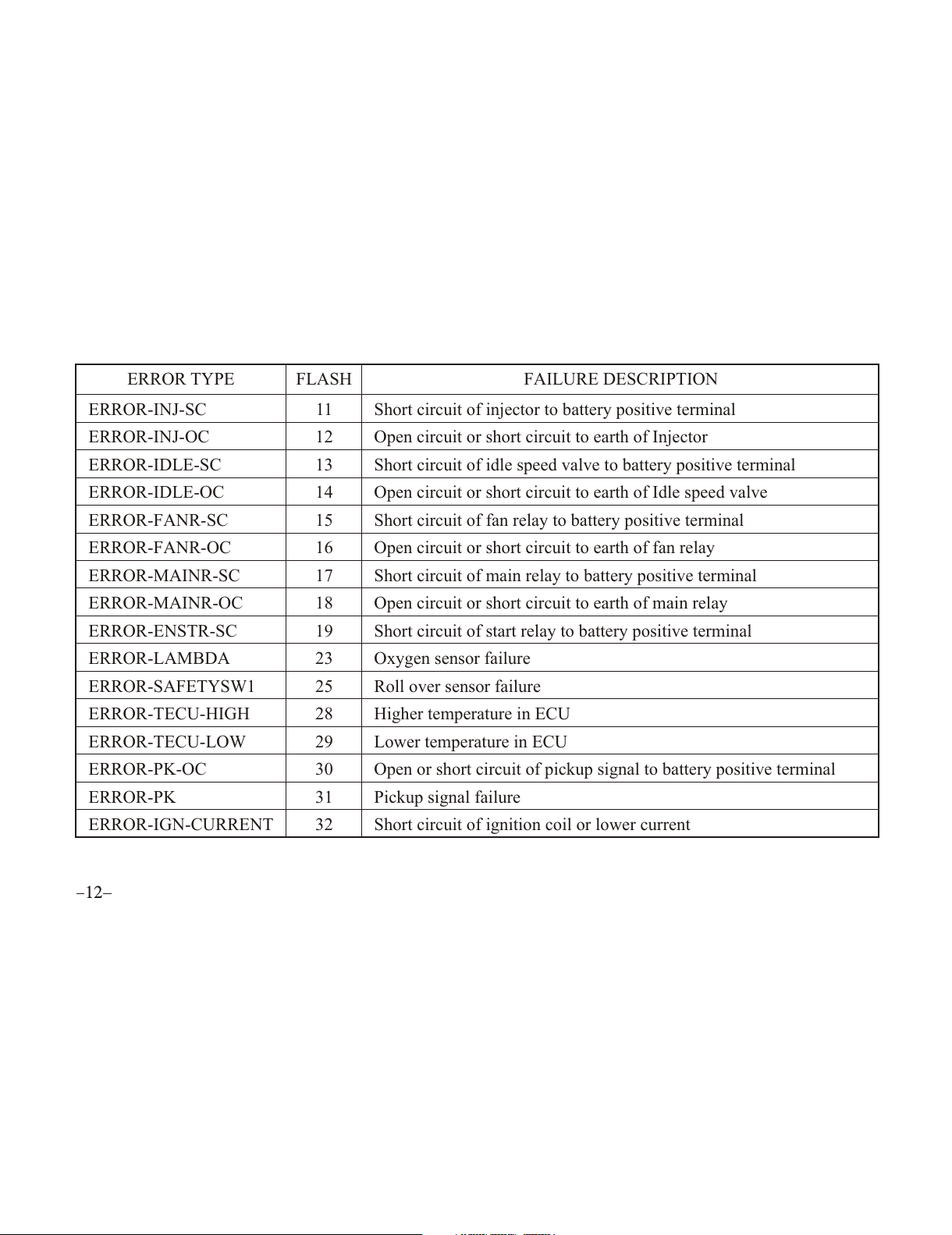
ERROR TYPE
ERROR-INJ-SC
ERROR-INJ-OC
ERROR-IDLE-SC
ERROR-IDLE-OC
ERROR-FANR-SC
ERROR-FANR-OC
ERROR-MAINR-SC
ERROR-MAINR-OC
ERROR-ENSTR-SC
ERROR-LAMBDA
ERROR-SAFETYSW1
ERROR-TECU-HIGH
ERROR-TECU-LOW
ERROR-PK-OC
ERROR-PK
ERROR-IGN-CURRENT
FLASH
11
12
13
14
15
16
17
18
19
23
25
28
29
30
31
32
FAILURE DESCRIPTION
Short circuit of injector to battery positive terminal
Open circuit or short circuit to earth of Injector
Short circuit of idle speed valve to battery positive terminal
Open circuit or short circuit to earth of Idle speed valve
Short circuit of fan relay to battery positive terminal
Open circuit or short circuit to earth of fan relay
Short circuit of main relay to battery positive terminal
Open circuit or short circuit to earth of main relay
Short circuit of start relay to battery positive terminal
Oxygen sensor failure
Roll over sensor failure
Higher temperature in ECU
Lower temperature in ECU
Open or short circuit of pickup signal to battery positive terminal
Pickup signal failure
Short circuit of ignition coil or lower current
All manuals and user guides at all-guides.com

Clock is in the lower of instrument. Open the
seat, remove electric unit waterproof cover, and two
adjust buttons can be seen. Clock adjust button (RH)
will be used to adjust the hour in clock, while
button (LH) to adjust the minute.
Engine oil indicator is on the lower side of
instrument for reminding the users to replace the
engine oil. Oil Replacing Interval 1st replacement within 500km then replace engine oil every 3000km
All manuals and user guides at all-guides.com
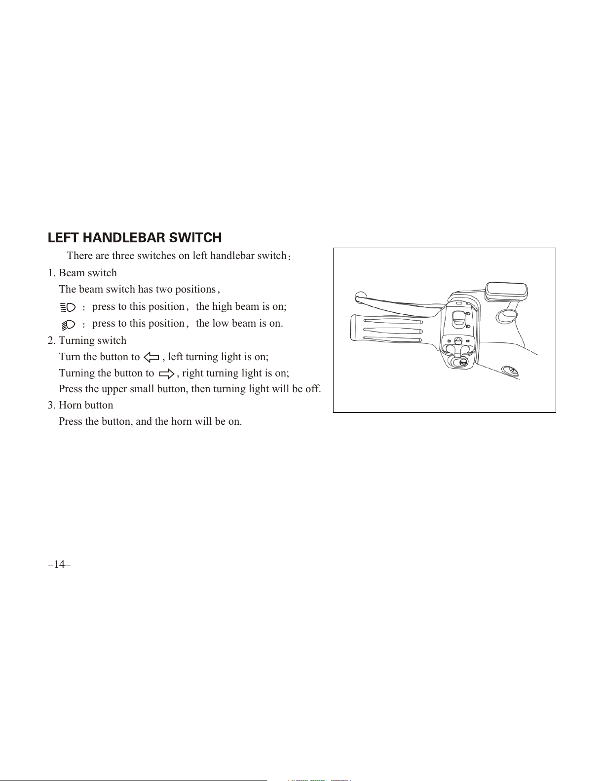
There are three switches on left handlebar switch
1. Beam switch
The beam switch has two positions
press to this position the high beam is on;
press to this position the low beam is on.
2. Turning switch
Turn the button to , left turning light is on;
Turning the button to , right turning light is on;
Press the upper small button, then turning light will be off.
3. Horn button
Press the button, and the horn will be on.
All manuals and user guides at all-guides.com

1. The illumination switch consists of three positions and :
when the switch is at this position headlight,
the pilot light, taillight and instrument light are
on
when the switch is at this position, the pilot light,
taillight and instrument light are on
When the switch is at this position, headlight, the
pilot light, taillight and instrument light are off.
2. Starting button
Press this button to start the engine. For detailed
procedures, please refer to Page 22.
3. Kill switch
Press the button and engine will be shut; Press the button , and engine can be started.
All manuals and user guides at all-guides.com
This manual suits for next models
3
Table of contents
Other CF MOTO Scooter manuals


