CGC Lawnaire IV User manual

TECHNICAL MANUAL
MAN 4125861
Rev. D 8-2007
MODEL:
544917
LAWNAIRE IV HONDA EC

CALIFORNIA
Proposition 65 Warning
Diesel engine exhaust and some of
its constituents are known to the State
of California to cause cancer, birth
defects and other reproductive harm.
Californie Proposition 65
Avertissement
Les échappements des moteurs diesel
et certains de leurs composés sont
reconnus par l’Etat de Californie pour
être cancérigènes, provoquer des
défauts congénitaux et d’autres dangers
en matière de reproduction.
ADVERTENCIA
AVERTISSEMENT
WARNING
The engine exhaust from this product
contains chemicals known to the State
of California to cause cancer, birth
defects or other reproductive harm.
California Advertencia
de la Proposicion 65
El estado de California hace saber que
los gases de escape de los motores
diesel y algunos de sus componentes
producen cáncer, defectos de
nacimiento y otros daños en el
proceso de reproducción humana.
L’
é
mission du moteur de ce mat
é
riel
contient des produits chimiques que
l’Etat de Californie consid
è
re
ê
tre
canc
é
rig
è
nes, provoquer des d
é
fauts
cong
é
nitaux et d’autres dangers en
mati
è
re de reproduction.
El estado de California hace saber
que los gases de escape de este
producto contienen productos
quÍmicos que producen cáncer,
defectos de nacimiento y otros daños
en el proceso de reproducción
humana.
CALIFORNIA
Proposition 65 Warning
Battery posts, terminals, wiring
insulation, and related accessories
contain lead and lead compounds,
chemicals known to the State of
California to cause cancer and birth
defects or other reproductive harm.
WASH HANDS AFTER HANDLING.

1
Lawnaire
IV
8-2007
IMPORTANT MESSAGE
Thank you for purchasing this CGC, Inc. product. You have purchased a world class product, one of the best
designed and built anywhere.
This machine comes with a Technical Manual containing safety, operation, parts, maintenance and service
information. The useful life and good service you receive from this machine depends to a large extent on how
well you read and understand this manual. Treat your machine properly, lubricate and adjust it as instructed,
and it will give you many years of reliable service.
Your safe use of this CGC, Inc. product is one of our prime design objectives. Many safety features are built in,
but we also rely on your good sense and care to achieve accident-free operation. For best protection, study the
manual thoroughly. Learn the proper operation of all controls. Observe all safety precautions. Follow all instruc-
tions and warnings completely. Do not remove or defeat any safety features. Make sure those who operate
this machine are as well informed and careful in its use as you are.
See a CGC, Inc. dealer for any service or parts needed. CGC, Inc. service ensures that you continue to receive
the best results possible from CGC, Inc. products. You can trust CGC, Inc. replacement parts because they are
manufactured with the same high precision and quality as the original parts.
CGC, Inc. designs and builds its equipment to serve many years in a safe and productive manner. For longest
life, use this machine only as directed in the manual, keep it in good repair and follow safety warnings and in-
structions. You'll always be glad you did.
Commercial Grounds Care, Inc.
One Bob Cat Lane
Johnson Creek, WI 53038-0469
TABLE OF CONTENTS....................................... FIGURES.................................................................... PAGE
SAFETY............................................................................................................................................................2
LABELS........................................................................................................................................................3, 4
ASSEMBLY/SET-UP INSTRUCTIONS .........................................................................................................5-7
CONTROLS......................................................................................................................................................8
OPERATION...............................................................................................................................................9, 10
SERVICE........................................................................................................................................................ 11
STORAGE ......................................................................................................................................................12
TRANSPORTING ...........................................................................................................................................13
VIBRATION LEVELS...................................................................................................................................... 14
SPECIFICATIONS.......................................................................................................................................... 15
NOTES ...........................................................................................................................................................16
PARTS SECTION........................................................................................................................................... 17
FRAME GROUP.................................................. FIGURE 1 ................................................................... 18, 19
MAIN GROUP-LAWNAIRE IV ............................. FIGURE 2 ................................................................... 20, 21
HANDLE GROUP................................................ FIGURE 3 ................................................................... 22, 23
TINE WHEEL GROUP......................................... FIGURE 4 ................................................................... 24, 25
DRUM GROUP.................................................... FIGURE 5 ................................................................... 26, 27
DECAL GROUP-LAWNAIRE IV .......................... FIGURE 6 ................................................................... 28, 29

2
Lawnaire
IV
MODEL NUMBER: This number appears on
sales literature, technical manuals and price lists.
SERIAL NUMBER: This number appears only
on your mower. It contains the model number
followed consecutively by the serial number.
Use this number when ordering parts or seeking
warranty information.
SAFETY
NOTICE !!!
Unauthorized modications may present extreme
safety hazards to operators and bystanders and
could also result in product damage.
Commercial Grounds Care, Inc. strongly warns
against, rejects and disclaims any modications,
add-on accessories or product alterations that are
not designed, developed, tested and approved by
CGC, Inc. Engineering Department. Any CGC, Inc.
product that is altered, modied or changed in any
manner not specically authorized after original
manufacture–including the addition of “after-market”
accessories or component parts not specically
approved by CGC, Inc.–will result in the CGC, Inc.
Warranty being voided.
Any and all liability for personal injury and/or property
damage caused by any unauthorized modications,
add-on accessories or products not approved by
CGC, Inc. will be considered the responsibility
of the individual(s) or company designing and/or
making such changes. CGC, Inc. will vigorously
pursue full indemnication and costs from any party
responsible for such unauthorized post-manufacture
modications and/or accessories should personal
injury and/or property damage result.
This symbol means:
ATTENTION!
BECOME ALERT!
Your safety and the safety of others is involved.
Signal word denitions:
The signal words below are used to identify levels
of hazard seriousness. These words appear in
this manual and on the safety labels attached
to CGC, Inc. machines. For your safety and the
safety of others, read and follow the information
given with these signal words and/or the symbol
shown above.
DANGER indicates an imminently hazardous
situation which, if not avoided, WILL result in death
or serious injury.
WARNING indicates a potentially hazardous
situation which, if not avoided, COULD result in
death or serious injury.
CAUTION indicatesa potentiallyhazardous situation
which, if not avoided, MAY resultinminoror moderate
injury. It may also be used to alert against unsafe
practices or property damage.
CAUTION used without the safety alert symbol
indicates a potentially hazardous situation which, if
not avoided, MAY result in property damage.
3
Lawnaire
IV
LABELS
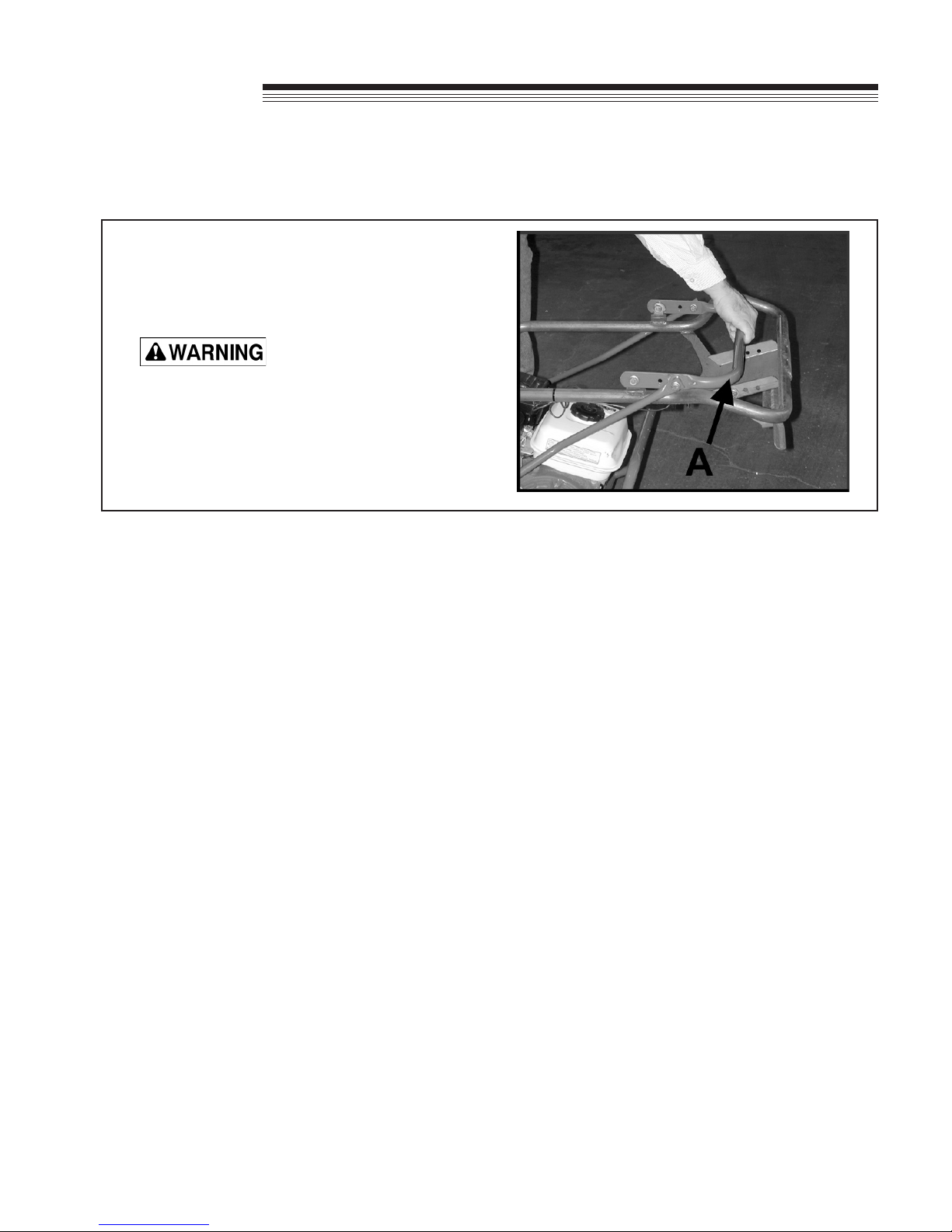
2000641
When Refueling:
- Stop Engine.
- Do not smoke.
- Do not spill fuel.
- Do not overll. Allow 25
mm for fuel expansion.
4115768
Throttle Control
– Move the throttle lever forward for increased
engine speed.
– Pull the throttle lever backwards for slower
engine speeds.
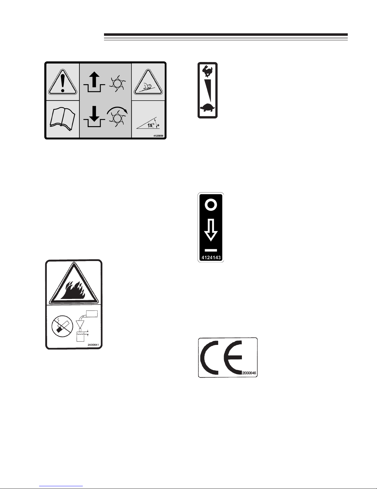
4127143
ON/OFF
- Rotate the switch so the pointer is up for the engine
"OFF" position.
- Rotate the switch so the pointer is down for the
engine "ON" position.
4125859
Operation & Safety Manual
- Read and understand Operation & Safety Manual.
- Replace if lost or damaged.
Drive Engagement
- Release the handle to disengage the clutch.
- Pull back on the handle to engage the clutch.
Slope Operation
- Do not use on slopes greater than 15o.
- Do not release the clutch handle on slopes, the unit
will freewheel down the slope.
2000646
EC Conformity
- Conforms to all EC directives applicable.

4
Lawnaire
IV
LABELS
840697
Belt Drive
– Keep safety shields in place.
– Keep hands and ngers away from belts.
Moving Components
– Keep hands away from moving components.
Servicing The Machine
– Disable the spark plug wire before performing
any service or maintenance.
– Read and understand the service section of the
operators manual.
009034760
Noise Emission
- Conforms to the specications of directive
2000/14/EC.
009034920
Hot Surfaces
- Do not touch hot surfaces.
- Mufer and engine components remain hot after
the engine is shut off.
Maintain a safe distance
– Keep area clear of people and pets.
– Check the work area for any rocks or other
objects to avoid.
524541
Rotating Tines
– Keep ngers and hands away from rotating tines.
– Keep feet and toes away from rotating tines.
Maintain a safe distance
– Keep area clear of people and pets.
– Check the work area for any rocks or other
objects to avoid.
5
Lawnaire
IV
GENERAL NOTE: FRONT, REAR, RIGHT HAND AND LEFT HAND REFERENCES
BELOW
ARE WITH RESPECT TO AN OPERATOR AT THE CONTROLS.
UNPACKING - Unpacking the aerator entails
securing the handle and rolling the unit off the
shipping pallet.
1. Cut the banding securing the aerator to the pallet
Banding is under tension and may snap back
when cut. Wear eye protection and stay clear
when cutting the band.
2. Unfold handle by pulling on the transport lift
handle A.
ASSEMBLY/SET-UP INSTRUCTIONS

6
Lawnaire
IV
ASSEMBLY/SET-UP INSTRUCTIONS
FOR LAWNAIRE IV MODELS
1. Flip the handle locking knobs Dup into position
over the handle bracket Eand tighten. HAND
TIGHTEN ONLY!.
2. Pull up on the transport lift handle Cto raise the
aerator to the transport position.
3. Carefully roll the unit off the pallet.
NOTE: If the folding handle will not be used, bolt the
handle in place. Use (2) 5/16-18 x 3/4" bolts and (2)
5/16-18 Nylock nuts.
CHECKING THE CLUTCH CABLE
The clutch cable is adjusted prior to shipping;
however, it should be checked before the unit is put
into service.
1. Pull the clutch control handle Dback and down
and make sure the idler engages the belt.
2. Release the clutch control handle Dand make
sure the belt disengages completely.
3. If adjustment is necessary, loosen nut Eon the
clutch spring hardware and adjust its position in
the slot of the clutch lever.
NOTE: Spring extension should not exceed .25" with
the clutch control handle pulled back.
7
Lawnaire
IV
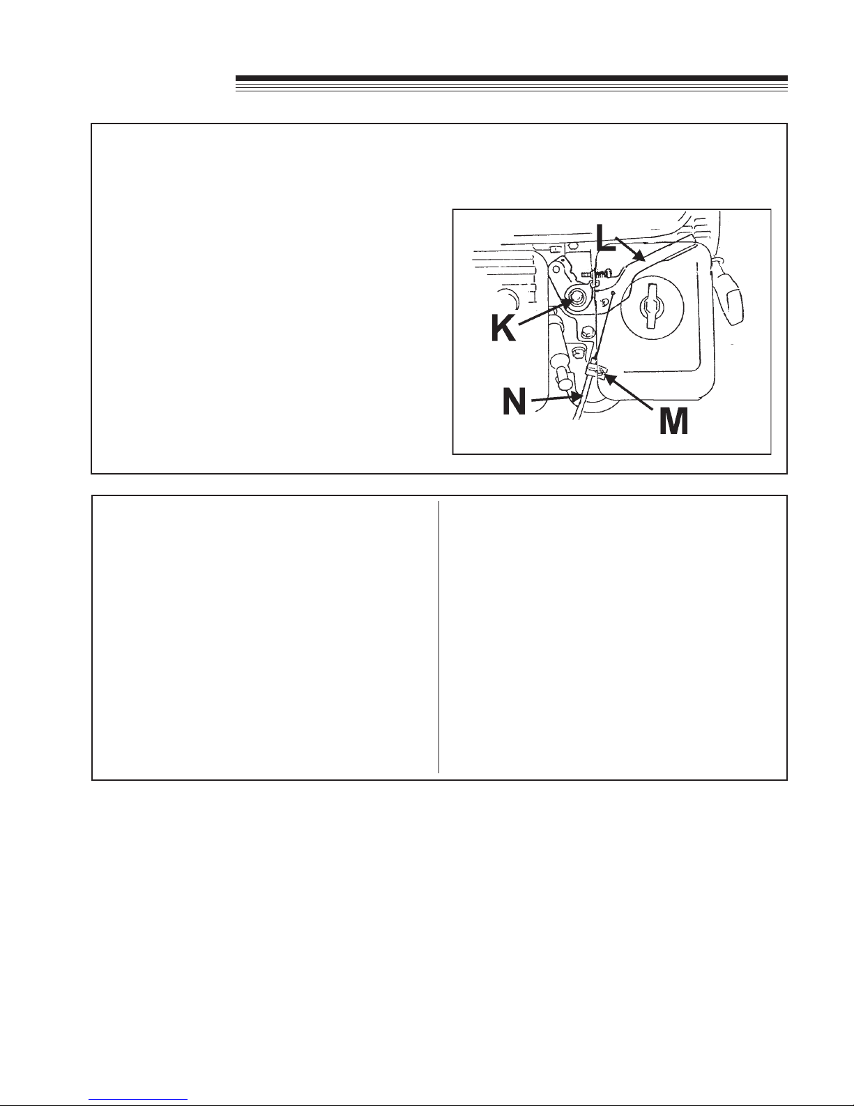
CHECKING THE THROTTLE CABLE- The throttle cable is adjusted prior to shipping; however, it should
be checked before the unit is put into service. The throttle control should freely move in a full range of
motion forward and backward. If necessary, the throttle cable can be adjusted as follows:
FOR HONDA ENGINES:
1. Loosen the throttle lever friction nut Kenough to
allow free movement of the throttle lever L.
2. Loosen throttle cable clamp M.
3. Push throttle lever Lall the way forward.
4. Push throttle cable sleeve Nup through cable
clamp until fully advanced.
5. Tighten the casing clamp screw M.
INITIAL BELT SEATING AND ADJUSTMENT
Proper tensioning of V-belts is the single most
important factor necesssary for long, satisfactory
operation. Too little tension will result in slippage,
causing rapid belt and pulley wear. Too much
tension can result in excessive stress on belts,
bearings, shafts, reduced efciency and operator
fatigue due to excessive force required to hold
the bail closed.
1. Operate the drive a few minutes to seat the belts
in the sheave grooves. Observe the operation of
the drive under its highest load condition (usually
starting).
2. Check the tension on a new drive serveral times
during the rst 24 hours of operation.
3. Keep the drive free of foreign material which
might cause slippage or damage to the belt and
sheave surfaces.
4. If a V-belt slips, it is too loose. NEVER apply belt
dressing, as this will damage the belt and cause
early failure.
5. Make sure pulleys stay in proper alignment.
Misaligned pulleys can result in belt rolling in the
pulley groove causing belt damage or breakage.
ASSEMBLY/SET-UP INSTRUCTIONS
8
Lawnaire
IV
CONTROLS
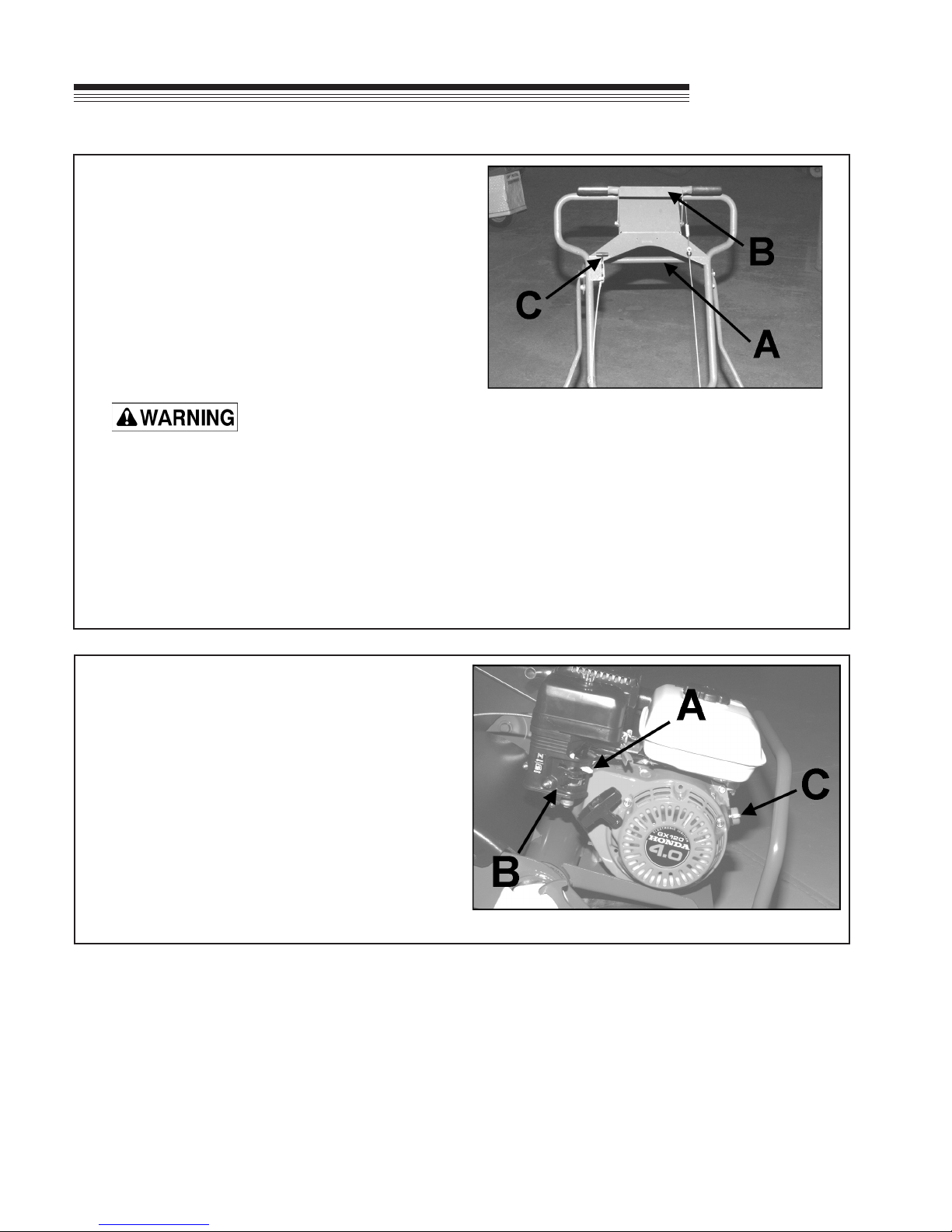
ENGINE CONTROLS
The Lawnaire IV is equipped with a 4 HP Honda
engine.
The engine is equipped with a choke A, a fuel
valve Band an On/Off switch C . The fuel valve
and the On/Off switch must both be in the "ON"
position to start the engine. Turn the On/Off
switch to "OFF" to stop the engine. Using the
choke will help start a cold engine. After the
engine starts, adjust the choke for best running
results. Once the engine warms, the choke
should not be needed.
HANDLE CONTROLS
Transport Lift Handle A - Pushing down on the
handle lowers the tines for aerating. Pulling the
handle up raises the tines so the aerator can be
moved or transported without incurring damage
to the unit or the turf.
Clutch Control Handle (Bail) B - Engages the belt
tightener clutch. Pulling back on the handle
engages the clutch; releasing the handle
disengages the clutch.
Releasing the clutch on an incline will cause
freewheeling, which will allow the unit to roll
down the incline.
Throttle Control C - The throttle control, located on
the handle, adjusts the engine speed. Pushing
the control forward increases the speed; pulling
the control back reduces the speed.

9
Lawnaire
IV
OPERATION
PRE-OPERATION CHECK
1. Visually check all moving parts and all fasteners.
If loose or broken, tighten or replace. Check
handle locking knobs and hand tighten if
necessary. Check for broken or bent tines;
replace if necessary
2. Check the engine crankcase and gear reduction
case oil levels with the engine resting in a level
position. Add oil if necessary.
3. Follow the engine manufacturer's
recommendations for the correct type and
amount of oil. Fill the fuel tank according to the
engine manufacturer's specications.
Gasoline is extremely ammable and highly
explosive under certain conditions. Always stop
the engine and do not smoke or allow open
ames or sparks when refueling. BE SURE to
install fuel cap after refueling.
NEVER start or run the engine inside where
exhaust fumes can collect. Carbon monoxide
present in the exhaust is an odorless and deadly
gas.
DO NOT operate equipment without shields in
place. DO NOT make adjustments or perform
any maintenance while the engine is running.
Before operating, check the area and remove
any object which may present a safety hazard or
damage the equipment.
This unit is not designed to be used on steep
slopes. To prevent injury and/or damage to
equipment, use extreme caution when operating
near terraces or hilly terrain. Travel up and down
slopes at a 45 degree angle rather than across,
to prevent unit from tipping over, DO NOT
release clutch handle on a slope; this will cause
freewheeling, allowing the unit to roll down the
slope.
10
Lawnaire
IV
OPERATION
AERATING
NOTE: For best performance and maximum tine
penetration, the lawn should be thoroughly
watered the day before aeration.
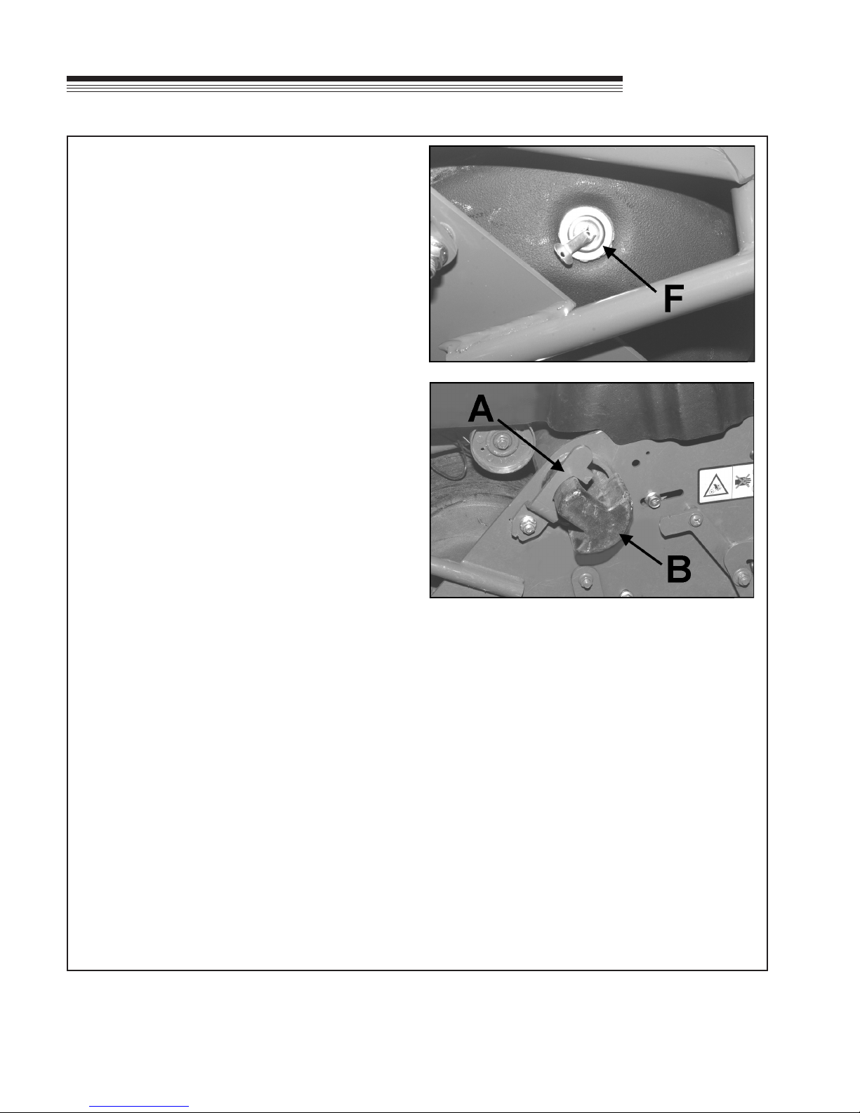
1. Rotate the water drum on the front of the unit
until the ller plug Fis positioned at the top.
Remove the plug, ll the drum with water and
replace the plug.
2. Place weights Bin large tube portion of the frame
(if not already installed) and secure in place on
each end with weight latches A.
3. Move the engine On/Off switch to the "ON"
position and then pull the recoil starter and choke
as required to start the engine.
NOTE: Fuel shutoff valve should be open.
4. Lift the transport lift handle if necessary to make
sure the tines are not touching the ground,
advance the throttle, slowly pull back on the
clutch handle control and transport the aerator to
the work area.
NOTE: Never cross hard objects or surfaces (such
as sidewalks, driveways, stepping stones, etc.) with
tines in the down position.
5. Upon reaching the work area, release the clutch control handle and adjust the throttle speed for aerating.
6. Push down on the transport lift handle, lowering the aerating tines to the turf.
7. Pull back slowly on the clutch control handle to start aerating.
NOTE: For maximum tine penetration into turf, apply downward pressure on the handle, until drum is off the
ground.
8. At the end of each aerating pass, release the clutch control handle, lift up on the handle assembly and
pivot the unit on the water drum. Resume aerating.
NOTE: For reverse, pull back on the handlebars when in the transport position.
9. When nished aerating, lift up on the transport lift handle to move the unit into transport position.
10. Drain the water drum when nished with aerating.

11
Lawnaire
IV
SERVICE
SERVICE
When replacement parts are required, use
genuine CGC, INC. parts or parts with equivalent
characteristics, including type, strength and
material. Failure to do so may result in product
malfunction and possible injury to the operator
and/or bystanders.
Any warning decal that becomes illegible should
be replaced immediately.
Do not operate equipment without shields in
place.
Do not make any adjustments or perform any
maintenance while the engine is running.
1. Thoroughly clean all tines inside and out when
aerating is completed and apply a light coat of oil
to prevent rust on tines.
2. Check the engine and gear reduction case oil
levels with the engine resting in a level position.
3. Inspect the air lter element and replace it if
necessary.
4. Lubricate the clutch pivot Gprior to each aerating
season or as needed.
5. Keep the drive belt free of oil and dirt and replace
if worn or damaged.
6. Keep the roller chain clean and in proper running
order. Lubricate using Lubriplate #13563;
available as Part No. 523248.
7. Check the roller chain for tightness and wear.
Adjust idler sprockets if necessary by loosening
the nut and screw holding the idler sprocket to
the frame and then sliding the sprocket in the slot
to the desired position. Tighten hardware.
NOTE: Excessive roller chain tightness will shorten
the life of the bearings. The chain Hshould have
movement of 1/8, to 1/4, (3mm to 6mm) deection at
the center point between the upper idler and drum
sprockets.

12
Lawnaire
IV
STORAGE
STORAGE INSTRUCTIONS
To prevent possible explosion or ignition of
vaporized fuel, do not store equipment with fuel
in tank or carburetor in enclosure with open ame
(for example, a furnace or water heater pilot
light).
Before the equipment is put in to storage for
any period exceeding 30 days, the following
steps should be taken.
1. Drain all fuel from the fuel tank and fuel lines.
2. Start the engine and run until all the fuel is used
from the carburetor oat bowl.
3. While the engine is still warm, drain the
crankcase oil and replace with the proper weight
oil corresponding to the season the equipment
will next be used.
4. Remove the spark plug and squirt a small
amount of engine oil into the cylinder. Turn the
engine over a few times to distribute the oil.
5. Drain the water drum.
NOTE: Always drain the water drum for winter
storage. Freezing water can rupture the drum.
6. Lubricate the clutch pivot tting.
To put the equipment into service after an
extended period of storage:
1. Check for loose parts and tighten if necessary.
2. Check for cracked or broken tines and replace as
necessary.
3. Fill the fuel tank.
4. Check the engine and gear reduction case oil
levels with the engine in a level position.
5. Start the engine.
6. Check for fuel leaks.
7. Check clutch control operation to make sure the
unit stops when the clutch control is released.

13
Lawnaire
IV
TRANSPORTING
TRANSPORTING
If a tote trailer will be used to transport the unit, the two
cast weights must be removed from the aerator frame
and a locking shaft installed in their place.
Removing the cast weights and draining the water
drum will decrease the weight for easier loading on a
vehicle or trailer.
To remove the weights, pull up on the latch A securing
the weights Band slide the weights out.
Use caution when removing the cast weights.
Each weight is approximately 22 lbs.
NOTE: Be sure to close the fuel shut off valve
before transporting the unit.
14
Lawnaire
IV
VIBRATION LEVELS
VIBRATION LEVEL
The machine was tested for whole body and hand/arm vibration levels. The operator was in the normal
operating position with both hands on the steering mechanism. The engine was running and the cutting
device was rotating with the machine stationary.
Standard ISO 5349: 1986 Mechanical Vibration
Guidelines for the measurement and the assessement of human exposure to hand transmitted vibration.
NOISE LEVEL
The machine was tested for noise levels according to Directive 2000/14/EC. The operator ear levels are
less than the 90dB pressure level requirement. Bystander noise levels are less than the guaranteed value of
100dB power level.
LAWNAIRE IV
HAND/ARM ACCELERATION
LEVEL
MAXIMUM LH OR RH ACCELERATION
VALUE m/s²
X Aeq U Aeq X Aeq
1.23 1.33 0.83
DOMINANT VALUE 1.33

15
Lawnaire
IV
LAWNAIRE IV
Dimensions:
Width.......................................... 28" (711 mm)
Length......................................... 51" (1295
mm)
Length (handle folded)............... 46" (1168 mm)
Height (transport)....................... 47.5" (1206 mm)
Height (handle folded)................ 30" (762 mm)
Net Weight:
Dry, w/o acc. weight................... 200 lbs. (91 Kg)
Dry, w/ acc. weight..................... 240 lbs.
(109 Kg)
With water tank full
and acc. weight.......................... 280 lbs. (127 Kg)
Speed:
Transport.......... up to 320 f.p.m. (97.5 M.p.m.)
SPECIFICATIONS
Aerate................. up to 305 f.p.m. (93 M.p.m.)
Engines:
Model 544917
Model.......................................... GX120K1HX
Honda, 4.0 h.p., 4 cycle
Starter......................................... Recoil, on/off switch
Governor.................................... 3600 RPM, no load
Idle Speed.................................. 1400 +- 100 RPM
Fuel Tank................................... .66 gal. (2.5 L)
Gear Reduction....................................... 6 to 1
Drive:
Primary....................................... V Belt, 4L section
Secondary..................... #40 plated roller chain
Wheels:
Front................. 11" (279 mm) Dia. water tank
5.2 gal. (19.7 L) max. capacity
Rear.................. 8 x 2.50 semi-pneumatic tires
with 3/4" ball bearings
Aeration:
Tines.... 3/4" (19 mm) formed from .08" hardened
chrome molybdenum alloy steel, 30 per unit
Penetration Depth..................... 2 3/4" (70 mm) max.
Swath Width.............................. 19" (483 mm)
Hole Pattern..... 3 3/4" x 7" (95 x 178 mm) on center
Production..................... Up to 28,975 sq. ft. / hour

16
Lawnaire
IV
NOTES
THIS PAGE LEFT BLANK INTENTIONALLY

17
Lawnaire
IV
PARTS
SECTION
PARTS SECTION

18
Lawnaire
IV
FIGURE 1
FRAME GROUP
Table of contents
Other CGC Tiller manuals


