CGX Dev Kit User manual

Dev Kit
This manual contains general operating instructions, precautionary measures,
maintenance instructions, and information for use of the CGX Dev Kit.
Please read this manual carefully and familiarize yourself with the controls and
accessories before using the product.
Note
• This is an investigational device designed for research and development eorts.
• It is not an FDA-approved medical device.
• There are no known side eects from the use of this product.
CGX A Cognionics Company
The Dev Kit is a portable development-
oriented, dry EEG system. The kit
includes an 8-channel amplifier and
individual leads terminating in snap
connectors. Also included are Drypad,
Flex, and HydroFlex sensors, and
a fabric headband for aid in sensor
placement.
Wireless technology allows the subject
to move about while real-time data is
collected and displayed.
EEG channels are sampled at a time
resolution of 500Hz and converted to
digital data at 24 bits of resolution.
The Dev Kit provides research-grade
signal quality and is ideally suited
for general-purpose EEG and ERP
research in laboratory and field
environments.
Description

2
Warnings
TheDevKitisintendedtobeusedto
acquiretheelectroenchephalogram
(EEG)andtransmititwirelesslytoa
computer.
ThisDeviceIsIntendedForResearchOnly.
ItIsNotIntendedForTheFollowingUses:
• monitoring of patients in a clinical
environment
• use in medical diagnosis
• on subjects undergoing surgery
• use in sterile environments
• use with sleeping subjects
DoNotUseThisProductInThese
Situations:
• near high-frequency surgical equipment
• if exposed to ionizing radiation
• in oxygen-rich environments (concentration
> 25% at 1 atm)
• in wet environments
• in the presence of ammable anesthetics
or gases
PrecautionsForThePractitioner
• Do not drop, sit on, or step on the amplier
or sensors.
• Check if your subject has a sensitive
dermatological condition causing sensor
intolerance.
• Avoid cross-subject contamination. Do not
use with subjects having open wounds or
scalp infections.
• The Dev Kit headset is not a diagnostic
tool. Any medical diagnosis related to
the EEG should be derived by a certied
physician.
SubjectConsiderations
• This device is intended for human use only.
• Subject should have a healthy scalp.
• Do not use with infants or neonates.
• Test subjects may or may not have hair.
• All sensors must be able to contact the
subject’s scalp.
• The entire headset may come into contact
with the subject’s skin.
FollowTheseAdvisoriesToKeepYour
DevKitInGoodWorkingOrder
• Do not immerse the amplier, sensors, or
leads in liquid.
• Do not expose the system to direct
sunlight or heat source, moisture, vibration,
mechanical shock, excessive dust, or
humidity.
• Do not open, modify or disassemble the
amplier — this will void the warranty.
• Do not use if the amplier or any
accessories are damaged.
• Do not use when amplier or leads are wet.
• Do not use caustic or abrasive cleaners on
the system or sensors.
AlwaysUseSuppliedAccessories
Using accessories other than those supplied
with your Dev Kit system may result in
damage or diminished ecacy of the system.
The Dev Kit uses an internal Lithium-ion
rechargeable battery.
AvoidCross-SubjectContamination
Clean the device and clean or replace
sensors after use following the cleaning
instructions to avoid cross-subject
contamination.

3
DeviceOverview
DevKitOverview
EEG is the measurement — through the use of sensors and
ampliers — of scalp surface electrical potentials arising
from activity in the cortex.
The Dev Kit is exible and adaptable to a wide variety
of custom EEG experiments. The eight sensor leads
can be placed anywhere around the head, and the
fabric headband keeps sensors in place around the
circumference of the head.
The Dev Kit meets the
mechanical, electrical, and
sensor needs required to
make an eective dry EEG
system.
Conventional wet systems
rely on electrolytic gels
to penetrate hair, contact
the skin, and provide a
conductive path. The gel
serves as a buer lling in
gaps between the sensor
and skin.
No conductive gel is used in a
dry system. The benets are
obvious: faster set-up, and no
after-use clean-up required.
Dry systems are subject to
several challenges. First, the
sensor must directly touch the
scalp or skin, even through
thick hair. Second, the sensor
must remain securely in place
to minimize artifacts and
noise. Finally, the electronics
must tolerate impedances up
to 200 times higher than wet
systems — while rejecting
noise and interference. A
high-end dry solution — like
the Dev Kit — balances
sensors, mechanics and
electronics achieving virtually
the same signal quality as a
traditional wet cap for most
EEG applications.
4
DeviceOverview
ThePackageContains
TheFollowingItems
Dev Kit Amplier
Bluetooth Dongle
1 Passive Ground Lead Wire
9 Active Lead Wires
10 Flex Sensors
10 Drypad Sensors
10 HydroFlex Sensors
30 Skintact Sensors
Headband
Wall Charger
Carrying Case
Manual
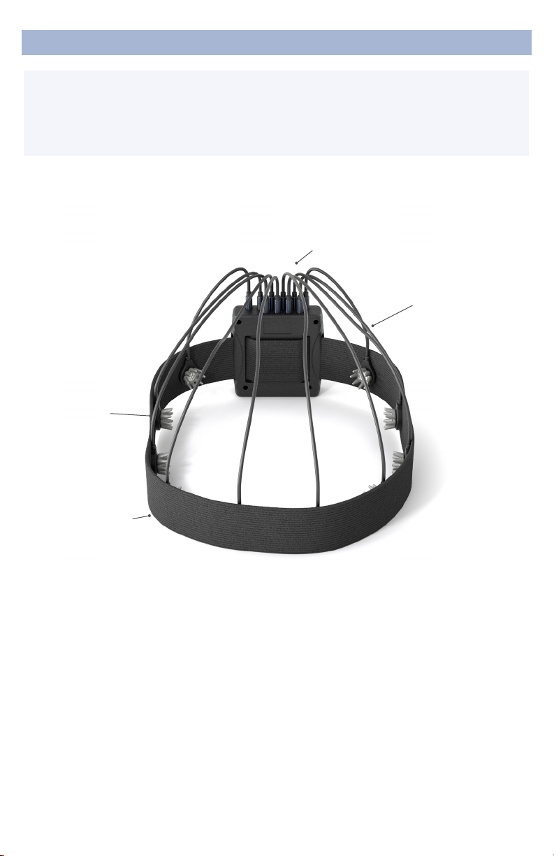
DevKitwithHeadband
Sensors
Active Lead Wires
Amplier
Headband
Optional AurisDK in-
ear sensors available
separately.

5
DeviceOverview
Amplifier
Wireless amplier
collects signals
and transmits to
Bluetooth Dongle.
BluetoothDongle
High-speed receiver
dongle plugs into
your computer’s
USB port.
ActiveLeadWires PassiveGround
LeadWire
Active lead wire
(3.5mm connector)
for EEG channels.
Passive lead
wire (touchproof
connector) for
Ground.
HydroFlexSensor
HydroFlex
sensors are extra
comfortable for
direct skin contact
and through-hair
applications.
FlexSensor
Flex sensors slide
through hair for
high-quality scalp
contact.
DrypadSensor
Drypad sensors
make direct
skin contact for
ECG and EEG
recordings.
AurisDKIn-Ear
Sensors
Optional in-ear
sensor with
replaceable foam
inserts.
6
Preparation
1.InstallTheSoftware
Note:CGXAcquisitionsoftwarerunsonWindows
only.
• Navigate to CGXSystems.com
• Select Software from the top navigation menu.
• Select DownloadunderCGXAcquisitionSoftware
• Choose the latest version link under “Downloading and
Installing the Software.”
• Extract the zipped le to your desktop.
• Run CGX Setup and follow the instructions.
• If you see a security warning, select MoreInfo and Run
Anyway
• The software will create a shortcut on your desktop.
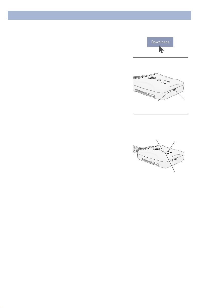
Download the latest software
from CGXSystems.com
2.ChargetheInternalBattery
Allow your Dev Kit to fully charge before each use. The
device has a charging indicator light:
• The charging status light is red when the battery is
charging.
• The charging status light is green when the battery is fully
charged.
3.CheckPowerStatusandTriggerStatusLightsOn
TopOfAmplifier
Power
Off Headset O
Green Headset On
Yellow Low Battery
Red Critically Low Battery (replace immediately)
Trigger
The Trigger Status Light is for use with the optional CGX
Wireless StimTrigger, and indicates when the headset is
receiving trigger signals from the StimTrigger unit.
Off Wireless StimTrigger Out Of Range
Blue Wireless StimTrigger In Range
Charging
Charger
Input
Charging
Status Light
Amplifier
Power Button
Power Status
Light
Status light for optional
Wireless StimTrigger

7
Preparation
4.InsertBluetoothDongle
Plug the dongle into your computer and Windows should
automatically install the correct drivers. Verify driver
installation by checking the Device Manager for problems,
marked by a yellow exclamation mark.
• The dongle is specic to each headset.
• For best performance, ensure a clear line of sight
between the dongle and the front of the headset
If Windows did not successfully install the driver for the
dongle, refer to the FTDI driver installation manual on
our website.
Each Dev Kit is permanently paired to a receiver dongle.
The pair automatically discover and initiate a connection
when both are powered on and within a 10m range.
The light on the dongle indicates its current state:
Green Power On, Not Paired
Purple Searching For Device
Blue Device Found
FlashingBlue Data Transmitting
5.StartTheAcquisitionSoftware
Once you’ve established a connection, data should begin
to stream.
Double click on the CGX Acquisition software icon. You
should see CGXDevKitunder DiscoveredDevices.
If you do not see the name CGX Dev Kit, remove and
re-insert the dongle and restart the software.
1. First, click the device name in this window to select the
Dev Kit
2. Then click Connect.
You should now see the device conguration window.
If you do not, double check to make sure the
Dev Kit is powered on.
Click StartDevice.
You will now see data streaming into the display. Click the
Channels tab on the top right-hand side of the program.
This will bring you to the impedance check. You are now
ready to use the device.
Dongle
Status Indicator Light

8
Preparation
6.SelectSensors
Drypad Sensors
Use Drypad sensors in positions where the subject has no
hair (forehead and bald areas).
Flex Sensors
Use Flex sensors to penetrate hair. On most subjects, these
are all the positions except Fp1, Fp2, F7 and F8.
HydroFlex Sensors
Use moistened HydroFlex sensors to penetrate hair, and
with sensitive subjects. Moistening with a dab of water prior
to use improves signal quality in dry environments.
Skintact Sensors
Use Skintact sensors for direct skin contact.
AurisDK In-Ear Sensors (optional)
Use AurisDK sensors for in-ear measurements.
7.Typical8-ChannelMontageUsingTheHeadband
This is a typical circumferential montage, with Reference at
the mastoid, and Ground set where convenient.
1. Insert the headband through the mounting slots on the
amplier.
2. Plug the passive touchproof ground connector into the
GGround port.
3. Plug an active 3.5mm lead into the RReference port.
4. Attach Skintact sensors to the Reference and Ground
leads. Ensure good contact between these sensors and
the skin.
Note: Reference and Ground contacts are essential to
the functioning of the device.
5. Connect as many leads as desired to the Dev Kit and
attach the sensor of your choosing to the end of each
lead.
6. Place the sensors around the head using the headband
to secure the leads in place.
Drypad Sensor for
direct skin contact
Flex Sensor for hair
HydroFlex Sensor for
sensitive subjects
AurisDK In-Ear Sensors
available separately
It may require extra pressure
to insert a sensor due to
variability in surface coating.
Try that sensor in an alternate
pod location in case of a
particularly tight t.
AttachSensorToLead
9
8.OptimizeSensorContact
After properly positioning the sensors on the subject, obtain
direct contact on all sensors before recording.
Bring up the impedance check in the CGX Data Acquisition
software under the Channels tab. The impedance check
presents a color-coded map of the sensors on the device,
corresponding to contact level:
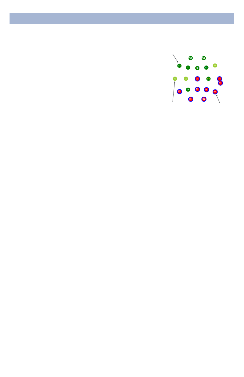
Red Impedance out of range
(>5,000 kΩ default)
Light Green Impedance at top end of range
(2,500-5,000 kΩ default)
Dark Green Impedance at bottom end of range
(<2,500 kΩ default)
The range of impedances with dry sensors may be higher
than what you are accustomed to when working with
conventional wet sensor ampliers. CGX devices utilize
a combination of advanced electronics, shielding, and
mechanics to obtain EEG signals even when contact is
poor, and can tolerate sensor impedance up to 5,000 kΩ.
9.AdjustSensors,IfRequired,ToImprove
ImpedanceMeasurements
Check for acceptable impedance measurements on each
channel.
To ensure good impedance measurements:
• Lift the sensor slightly to move hair aside.
• Lower the sensor back in place, keeping the sensor
aligned to the subject’s head.
• Lightly press down, holding for 5 seconds, then gently
release the sensor.
10.RecordAnEEG
After you have acceptable impedance levels, click Record
under the Device tab to begin your recording. To end the
recording, under the same tab, click StopRecording.
11.EndTheSession
Close out the current le in the software if one is active and
exit the program. Press the power button once to turn o
the device.
DonningInstructions
Ground must be applied for
impedance check to operate.
ImpedanceMap
UnderTheChannelsTab
Marginally
Acceptable Unacceptable
Acceptable
PositionOfTheSubject
DuringEEG
Use the Dev Kit headset
for subjects in an upright
position. Do not let the
subject lie or sleep on the
sensors. It may damage the
system.

10
CleaningAndMaintenance
To avoid cross-subject contamination, follow the cleaning
instructions to clean sensors, amplier, and headband after
each use.
This device is not intended to be sterilized in an autoclave.
CleaningSensors
• Use hand sanitizer or 70% isopropyl-based alcohol wipes
to clean Drypad and Flex sensors according to cleaning
agent instructions.
• Do not use 90% or 99% alcohol. These solutions will
damage the sensors.
• Check sensors regularly. Sensor functionality is important
to maintaining signal quality. Replace sensors if signal
quality degrades.
• Contact CGX for replacement sensors.
CleaningTheLeadsandAmplifier
• Use 70% isopropyl-based alcohol wipes to clean the
leads and amplier.
• Do not use 90% or 99% alcohol. These solutions will
damage the system.
Storage
• Transport system in the case.
• Store in a temperature and humidity controlled room.
DoNotLetTheAmplifierComeIntoContact
WithLiquid
Immediately turn o the system out and let the amplier dry
completely before resuming use.
DisposalInstructions
To protect the environment, always follow local law, rules,
and policies regarding electronic and battery disposal. You
may also return the device to CGX for proper disposal.

11
The most important aspect of EEG recording is that
output data is only as good as the recording input. While
algorithms exist to remove artifacts, poorly recorded data
cannot be xed in post processing.
Recording good EEG data requires preparation of the
participant for optimal sensor contact:
1. Participants should have their hair recently washed
and fully dried before recording. Wet hair, hair gel,
conditioners, and hair spray may cause interference and
degrade signal quality.
2. Clean each sensor location on the head with a cotton
swab soaked with alcohol.
3. In the event of diculty establishing good contact, apply
a small amount of water between the sensor and scalp
to create an electrical bridge.
4. It is important for subjects to reduce tension in the
head, neck, and shoulders during readings.
ObtainingCleanEEGData
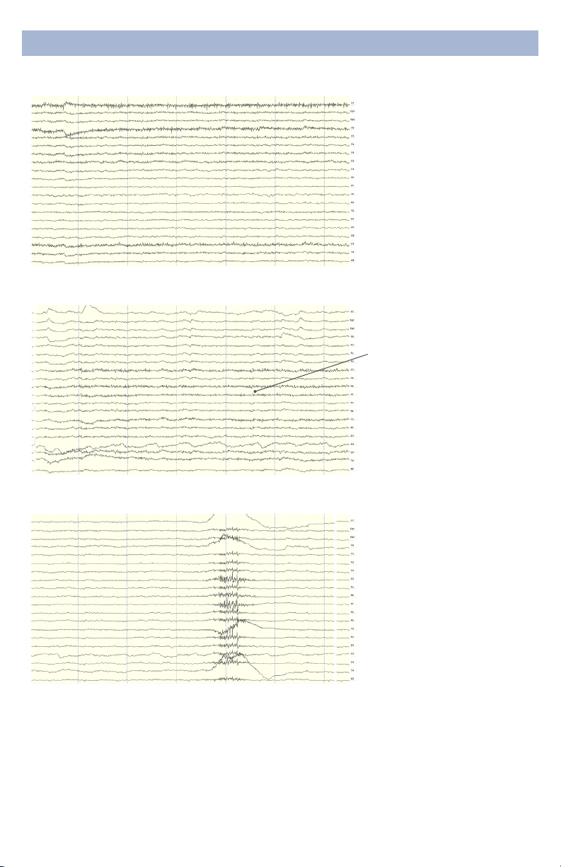
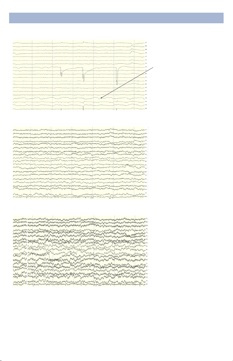
TypicalCleanDataRecording
This is a representation of a
clean data recording.

12
UnderstandingReadings
Traces are thin and deviate
minimally from the axis.
CleanDataAtDefaultScale
Eye blinks will generate
muscle artifacts in the
frontopolar locations (Fp1
and Fp2) and less so in
frontal sensors (F3/F4, F7/F8),
overshadowing brain activity
in EEG recordings.
Blinks
Moving the eyes will generate
muscle artifact in the forehead
and front of the head. A high
concentration of neurons
in the eyes generate strong
electromagnetic elds, so eye
movement causes disruptions
in the EEG recording.
EyeMovement
13
Jaw clenching may aect
most or all channels,
especially if clenching hard.
Light jaw clenching or
tightness can be observed
in F7/F8, T3/T4. Take note
of any temporomandibular
joint disorders: these can
cause artifact without typical
clenching.
The tongue is a large
polarized muscle, with the
tongue’s tip negative with
respect to the base of the
tongue. When the tongue
moves around the mouth,
it generates a moving eld
causing recording disruptions.
Disruptions may be seen
down the midline (Fz, Cz, Pz).
Tongue movement during
talking can be seen on many
channels.
UnderstandingReadings
MuscleArtifact:JawClench
MuscleArtifact:TongueMovement
Swallowing invokes
movement of several muscles
in the mouth, including the
tongue, causing disruption
of many channels. Ignore
swallowing if infrequent, but
frequent swallowing may limit
usable data.
MuscleArtifact:Swallowing

14
Neck tension may aect
channels on the back of the
head, predominantly O1/O2,
but also in parietal sensors
(Pz/P3/P4, P7/P8). Subjects
should be comfortably seated,
with appropriate bracing at
the back and neck. Avoid
slouching.
Brief disruptions in contact
between sensor and scalp
may cause “sensor pops” on
recordings. Occasional pops
can usually be ignored in
processing, but if the problem
persists, check the contact
between the sensor and
scalp. Wipe popping locations
with a small amount of alcohol
on the sensor.
MuscleArtifact:NeckTension
HeadsetOrElectrodeDisruptions:SensorPops
UnderstandingReadings
Excess or quick movement
of the head may disrupt
connection between sensors
and scalp causing data
artifacts as shown.
HeadsetOrElectrodeDisruptions:HeadMovement
15
EEG sensors are sensitive
enough to detect small
electrical signals on the
cortex. Occasionally, sensors
may lie directly atop a blood
vessel. When this occurs,
sensors may detect the
subject’s pulse. Slightly move
the sensors to reduce pulse
artifacts.
Power lines operate between
50 and 60 Hz. Unsecure
power sources may leak
electromagnetic frequencies.
Because EEG records
frequencies from 1hz to about
40hz, power line noise may
negatively impact recordings
on all channels. This is
especially the case when
connection between sensor
and scalp is poor.
UnderstandingReadings
PulseArtifact
MildPowerLineArtifact
To avoid power line artifacts,
have subjects sitting at
least 3 feet from power
cords, plugged-in devices,
and lighting or overhead
uorescent lights. The
Dev Kit shields the sensors
from environmental noise,
but issues can still occur with
poor skin contact.
StrongPowerLineArtifact
16
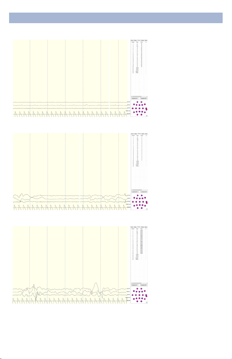
UnderstandingReadings
There are a multitude of
recording errors when the
A1 reference earclip is not
connected to the subject.
The most common are:
• Impedances match or
nearly match at a low value
but do not appear on the
display or in the impedance
head map. (g. 1)
• No traces appear and
impedance values are zero.
(g. 2)
• No traces appear and
impedance values are high.
(g. 3)
ImproperSetup:NoConnectedReference
g. 1
g. 2
g. 3
17
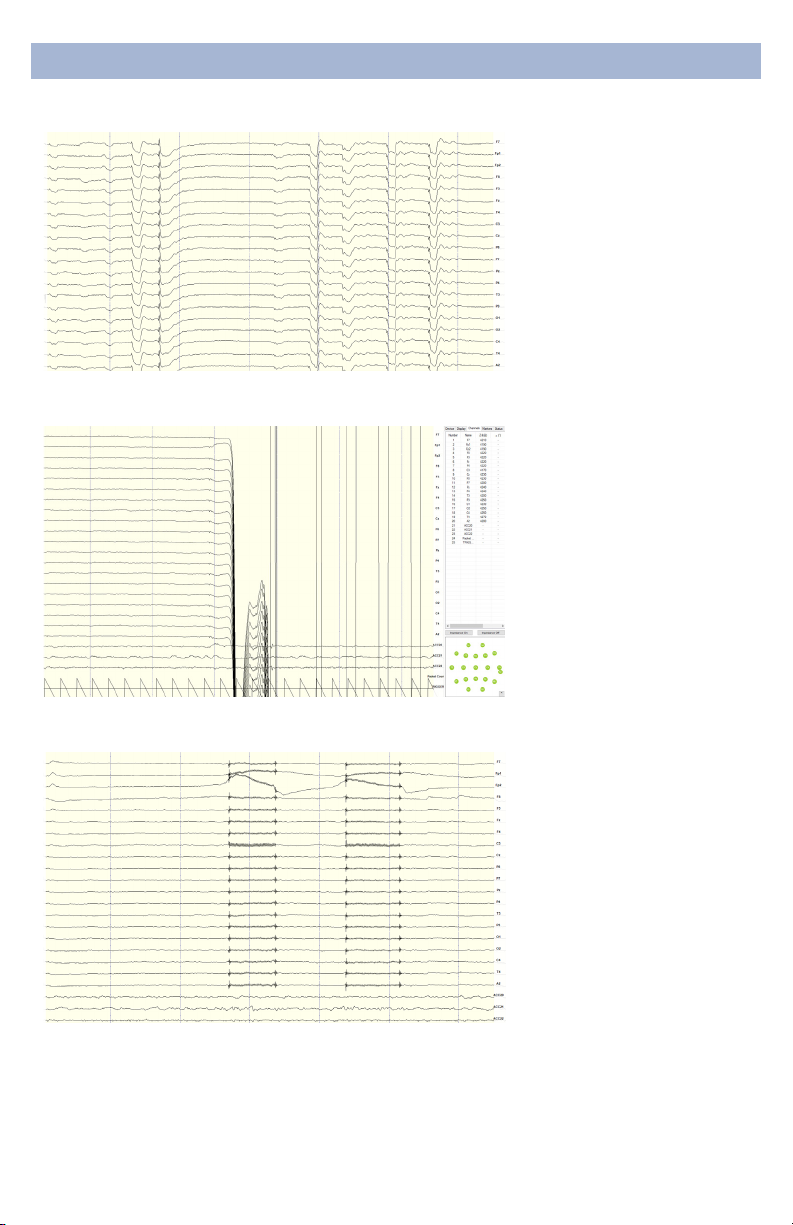
UnderstandingReadings
When the reference channel
is touched or jostled, all
channels will be aected.
Avoid disrupting the
Reference position during
use.
When the reference is
disconnected, all channels will
disconnect as well.
ImproperSetup:ReferenceContact
ImproperSetup:ReferenceDisruption
If the ground has poor
contact, all channels will be
impacted. Avoid disrupting
the connection of the Ground
lead during use.
ImproperSetup:GroundDisruption

18
SoftwareReference
DeviceConfiguration
• DiscoveredDevicesConnected dongles will be listed
here. Select the device name of your system and hit
Connect.
• The software automatically connects to your device to
retrieve stored settings.
• The DeviceConfigurationwindow is only for your
information; changing the settings will not change the
conguration of the device. If you need to change device
conguration, contact support at CGX.
DataRecording
• Record Click to open a le dialog. Select the desired
location, le name, and le type. (CSV les have a time
stamp built in). Recording begins when you press OK.
• ToStopRecordinghit the button again. Elapsed time is
shown in the box above the button.
• StartLabStreamingLayerHit the Start
LabStreamingLayerbutton.
• StartRDAServer To use the BCI2000 software with the
Data Acquisition Software, click on this button. Then,
connect to the application in BCI2000.
• Timer The timer allows you to limit le recording to a
specic length.
DeviceTab
19
SoftwareReference
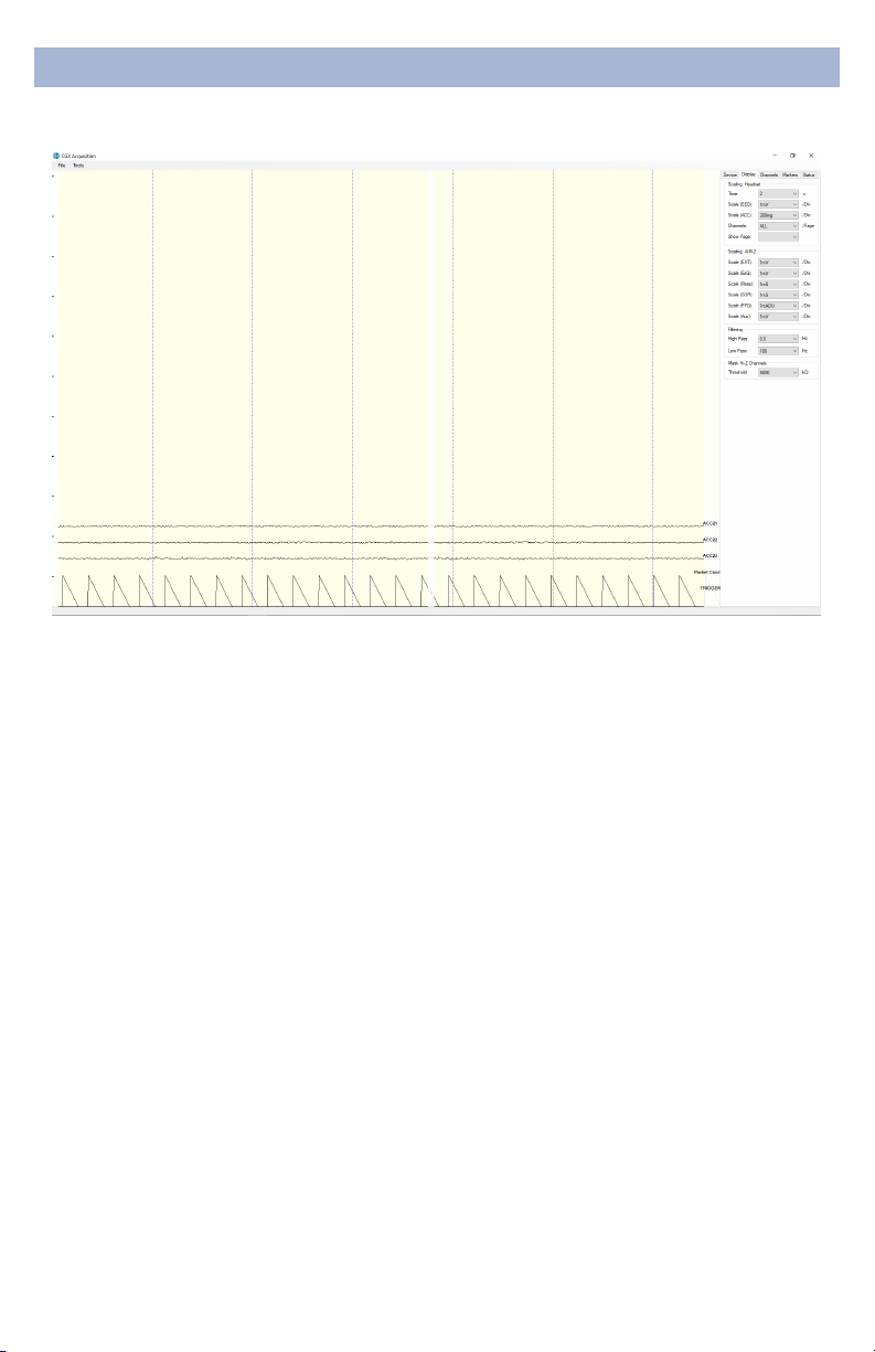
DisplayTab
The display tab controls
scaling and other viewing
parameters for the signals.
Scaling:Headset
• Time sets the x axis time window. By default, it is set to 2
seconds.
• Scale(EEG) sets the y axis vertical gain for the EEG
channels on the head.
• Scale(ACC) sets the y axis vertical gain for the
accelerometer channels.
• Channels sets the maximum number of channels
displayed per screen. To ip through the pages of
channels, use the option below.
• ShowPage switches between dierent pages of
channels.
Scaling:AIM-2(Optional)
Filtering
• HighPass sets the oor (removes osets and slow
signals) corner frequency for the display.
• Lowpass sets a ceiling (removes high frequency signals
and noise) corner frequency for the display.
• Note: ltering is for display only. Data les are saved
raw and unltered to preserve the maximum amount of
information.
MaskHi-ZChannels
Threshold hides channels with sensor impedances above
the specied threshold from the display.

20
SoftwareReference
The top half of the Channels
tab contains a table
displaying information about
each channel in the system
including its number, name,
contact impedance (Z (kΩ))
and sensor oset (O (mV)).
The oset is calculated
relative to the reference
channel.
ChannelsTab
The bottom half is a graphical map of sensor contact
quality. Red circles indicate poor contact, whereas light
green circles indicate acceptable contact. Dark green
circles indicate ideal contact.
The threshold for this contact quality is, by default:
Red Above 5000 kΩ
LightGreen Between 2500-5000 kΩ
DarkGreen Below 2500 kΩ
This threshold can be changed with the Mask Hi-Z menu
on the display tab.
Red 100% or greater of Hi-Z threshold
LightGreen Between 50%-100% of Hi-Z threshold
DarkGreen Below 50% of Hi-Z threshold
Table of contents
Other CGX Medical Equipment manuals

Popular Medical Equipment manuals by other brands


Mac Medical
Mac Medical S0202-EST-KT instruction manual

Ossur
Ossur PRO-FLEX PFP0xyyz Instructions for use

Cardioline
Cardioline ar1200view user manual

DECK MOUNT
DECK MOUNT MO2 user manual

Nasco Healthcare
Nasco Healthcare Canine IV Leg instruction manual

Drive Medical
Drive Medical Clini-Ox II Instructions to user

Dynatronics
Dynatronics DYNATRON SmarTRAC Operator's manual

Drive Medical
Drive Medical GRAVIMED Protexx operating instructions

HoMedics
HoMedics HDS-1000-GB instruction manual

Synthes
Synthes CODMAN NEURO CODMAN CERTAS Plus manual

Nasco
Nasco Life/form LF01005U instruction manual

SIGNIFY
SIGNIFY Alkco EvoSeal 442296094811 instruction sheet