Instruction Manual
MAN-028 9www.macmedical.com
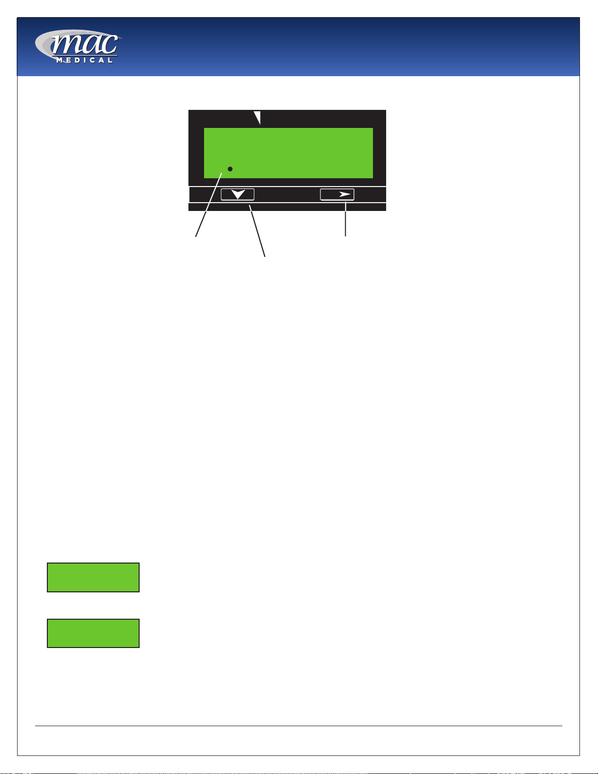
Timer Operation Display and Programming
Time Display: Accumulates time when the timing start input is active. Timing will not take
place when the external or front panel reset is active. The leftmost digit is the time value
legend.
Down Key: When the program input is active this key is used to scroll through the menu items.
After a menu item has been chosen for editing, the down key is used to set the value for the
currently selected (ashing) digit.
Next/Reset Key: Resets the accumulated time if Front Panel Reset is enabled in Programming
Mode. When the program input is active this key is used to select a menu item for editing
(leftmost digit will begin to ash) and then move to the desired digit to be changed.
Programming -
Programming parameters can be accessed, when the Program Enable input is active, by
pressing the Down key. To edit a parameter use the Down key to scroll until the desired
parameter appears on the screen. Pressing the Next key will cause the leftmost digit of that
value to begin to ash. Use the Next and Down keys in combination to choose individual
digits and change their value.
Front Panel Reset Enable: When active (ON) the time value, when being
displayed, can be reset by pressing the Next/Reset key. If set to OFF, the
time value can only be reset through the remote input.
Time Format: Sets the units in which the elapsed time will be
accumulated. Use the next key to scroll through the available choices:
Seconds, Minutes (_ _ _ _ _ . _), Hours (_ _ _ _ _ . _) , Hours: Minutes:
Seconds.
Note: On initial start-up, as well as after any programming changes, it is
necessary to reset the unit before beginning operation
R
1. Time Display 3. Next/Reset Key
345678S
EAGLE SIGNAL
o n
_ _ _ _ _ _
S .
1 .