CH Hanson Norse 9681115 Instructions for use

6˝ x 9˝
Belt/Disc
Sander
Operating Instructions & Parts Manual
9643069.01 0518
Model 9681115
9681115_oipm_En012_9643069.01 0518 05/22/18 Page 1

2
GE ING S AR ED
SAFE Y / SPECIFICA IONS
ASSEMBLY / INS ALLA ION
OPERA ION
ROUBLESHOO ING
MAIN ENANCE / REPAIR
NO SE Operating Manual & Parts List 9681115
Please read and save hese ins ruc ions. Read carefully before a emp ing o assemble, ins all,
opera e or main ain he produc described.
Pro ec yourself and o hers by observing all safe y informa ion. Failure o comply wi h ins ruc ions
could resul in personal injury and/or proper y damage! re ain ins ruc ions for fu ure reference.
Model #: ________________________
Serial #: _________________________
Purchase Da e: ___________________
9681115_oipm_En012_9643069.01 0518 05/22/18 Page 2
GETTI G STARTED
Structural Requirements
Make sure all supporting structures and load attaching devices are
strong enough to hold your intended loads. If in doubt, consult a
qualified structural engineer.
Electrical Requirements
The power supply to the Sander needs to be 120 volt/ 8.0 amp,
single phase, 60 Hz. The standard allowable voltage variation is
plus or minus 10%.
Tools eeded:
Standard mechanic’s hand tool set.
U PACKI G
Be careful not to touch overhead power
lines, pipin , li htin , etc. if liftin
equipment is used. Sander wei hs approximately 88 lbs,
proper tools, equipment and qualified personnel should be
employed in all phases of unpackin and installation.
Cartons should be handled with care to avoid damage from
dropping, bumping, etc. Store and unpack cartons with correct side
up. After unpacking Sander, inspect carefully for any damage that
may have occurred during transit. Check for loose, missing or
damaged parts. If any damage or loss has occurred, claim must be
filed with carrier immediately. Check for completeness. Immediately
report missing parts to dealer.
Sander is shipped partially assembled. End user will need to
assemble loose parts to machine.
IMPOR AN : The tool has been coated with a protective coating.
In order to ensure proper fit and operation, the coating must be
removed. Remove coating with mild solvents such as mineral
spirits and a soft cloth. Nonflammable solvents are recommended.
After cleaning, cover all exposed metal surfaces with a light coating
of oil.
Never use hi hly volatile solvents. Avoid
ettin cleanin solution on paint as it
may tend to deteriorate these finishes. Use soap and water
on painted components.
Contents:
• Sander (1)
• Miter gauge assembly (1)
• Fence support (1)
• Table assembly (1)
• Hardware bag (1)
• Rubber foot (4)
• Hex wrench (1)
• Operating Instructions and Parts Manual (1)
Unpack:
• Carefully unpack Sander from carton. Do not discard packing
materials until after machine has been inspected for damage
and completeness. Locate loose parts and set aside.
Inspect:
• After unpacking the unit, carefully inspect for any damage that
may have occurred during transit. Check for loose, missing or
damaged parts. Shipping damage claims must be filed with the
carrier.
• All tools should be visually inspected before use, in addition to
regular periodic maintenance inspections.
• Be sure that the voltage labeled on the unit matches your
power supply.
• See General Safety Instructions, Cautions and
Warnings as shown.
SAFETY RULES
For your own safety, read all of the
instructions and precautions before
operatin tool.
PROPOSI ION 65 WARNING: Some dust created by
using power tools contain chemicals known to the state
of California to cause cancer, birth defects or other
reproductive harm.
Some examples of these chemicals are:
• Lead from lead-based paints.
• Crystalline silica from bricks and cement and other masonry
products.
• Arsenic and chromium from chemically-treated lumber.
Your risk from these exposures varies, depending on how often you
do this type of work. To reduce your exposure to these chemicals:
work in a well ventilated area and work with approved safety
equipment. Always wear OSHA/NIOSH approved, properly fitting
face mask or respirator when using such tools.
Always follow proper operatin
procedures as defined in this manual even
if you are familiar with the use of this or similar tools.
Remember that bein careless for even a fraction of a
second can result in severe personal injury.
Be Prepared for Job
• Wear proper apparel. Do not wear loose clothing, gloves,
neckties, rings, bracelets or other jewelry which may get
caught in moving parts of machine.
• Wear protective hair covering to contain long hair.
• Wear safety shoes with non-slip soles.
• Wear safety glasses complying with United States ANSI Z87.1.
Everyday glasses have only impact resistant lenses. They are
NO safety glasses.
3
NO SE Operating Manual & Parts List 9681115
GE ING S AR ED SAFE Y / SPECIFICA IONS ASSEMBLY / INS ALLA ION OPERA ION ROUBLESHOO ING MAIN ENANCE / REPAIR
9681115_oipm_En012_9643069.01 0518 05/22/18 Page 3

SAFETY RULES (CO TI UED)
• Wear face mask or dust mask if operation is dusty.
• Be alert and think clearly. Never operate power tools when
tired, intoxicated or when taking medications that cause
drowsiness.
Prepare Work Area for Job
• Keep work area clean. Cluttered work areas invite accidents.
• Do not use power tools in dangerous environments. Do not
use power tools in damp or wet locations. Do not expose
power tools to rain.
• Work area should be properly lighted.
• Proper electrical receptacle should be available for tool. Three-
prong plug should be plugged directly into properly grounded,
three-prong receptacle.
• Extension cords should have a grounding prong and the three
wires of the extension cord should be of the correct gauge.
• Keep visitors at a safe distance from work area.
• Keep children out of workplace. Make workshop childproof.
Use padlocks, master switches or remove switch keys to
prevent any unintentional use of power tools.
Tool Should Be Maintained
• Always unplug tool prior to inspection.
• Consult manual for specific maintaining and adjusting
procedures.
• Keep tool lubricated and clean for safest operation.
• Remove adjusting tools. Form habit of checking to see that
adjusting tools are removed before switching machine on.
• Keep all parts in working order. Check to determine that the
guard or other parts will operate properly and perform their
intended function.
• Check for damaged parts. Check for alignment of moving
parts, binding, breakage, mounting and any other condition
that may affect a tool’s operation.
• A guard or other part that is damaged should be properly
repaired or replaced. Do not perform makeshift repairs. (Use
parts list provided to order repair parts.)
Know How to Use Tool
• Use right tool for job. Do not force tool or attachment to do a
job for which it was not designed.
• Disconnect tool when changing the belt or abrasive disc.
• Avoid accidental start-up. Make sure that the tool is in the OFF
position before plugging in.
• Do not force tool. It will work most efficiently at the rate for
which it was designed.
• Keep hands away from moving parts and sanding surfaces.
• Never leave tool running unattended. Turn the power off and
do not leave tool until it comes to a complete stop.
• Do not overreach. Keep proper footing and balance.
• Never stand on tool. Serious injury could occur if tool is tipped
or if blade is unintentionally contacted.
• Know your tool. Learn the tool’s operation, application and
specific limitations.
• Use recommended accessories. Use of improper accessories
may cause risk of injury to persons.
• Handle workpiece correctly. Protect hands from possible injury.
• Turn machine off if it jams. Belt jams when it digs too deeply
into workpiece. (Motor force keeps it stuck in the work.)
• Support workpiece with miter gauge, belt platen or work table.
• Maintain 1/16˝ maximum clearance between table and sanding
belt or disc.
Think safety! Safety is a combination of
operator common sense and alertness at
all times when tool is bein used.
Do not attempt to operate tool until it is
completely assembled accordin to
instructions.
SPECIFICATIO S
Belt size 6 x 48˝
Belt platen area 6 x 141⁄2˝
Belt drum dimensions 27⁄8x 61⁄8˝
Table dimensions 6 x 111⁄2˝
Table tilts 0 to 45º
Dust chute diameter 2˝
Belt speed 1836 SFPM
Disc diameter 9˝
Disc speed 2510 RPM
Base dimensions 12 x 181⁄8˝
Switch SP, Locking rocker
Motor 1 HP, 120 V, 8.0 Amps
Weight 72 lbs
Shipping weight 76 lbs
4
GE ING S AR ED
SAFE Y / SPECIFICA IONS
ASSEMBLY / INS ALLA ION
OPERA ION
ROUBLESHOO ING
MAIN ENANCE / REPAIR
NO SE Operating Manual & Parts List 9681115
9681115_oipm_En012_9643069.01 0518 05/22/18 Page 4

ASSEMBLY
Do not attempt assembly if parts are
missin . Use this manual to order repair
parts.
the sander must NOT be plu ed in and
the power switch must be in the "OFF"
position until assembly is complete.
Installing the Foot Pads
Four rubber foot pads are supplied to protect your work surface,
and to reduce any vibration that may develop when the sander is
operating.
1. Tilt the sander up and slide the feet onto each of the four
corners of the sander. No hardware is needed. See Figure 1.
Installing the Sanding Belt Fences
The sander includes two fences for use with the sanding belt. The
small fence/platen attaches directly to the sanding belt frame, and
is used for supporting small items being sanded.
The larger fence/platen attaches onto the small fence. It gives a
larger support surface for sanding large work pieces.
NOTE: These parts may be pre-assembled at the time of delivery.
If not, follow the following parts assembly:
1. Install the small fence onto the sanding belt frame with the four
hex screws and washers. See Figure 2.
2. Insert two star-head screws through the countersunk holes in
the large fence and install the knobs on their threaded ends.
(Washers shown in Figure 3 are optional, not included with
sander).
3. Slide the large fence’s two screws with knobs over the two
slots in the small fence and fasten in place. Pending on the
material being sanded, the large fence can easily be removed
by just loosening the two knobs and sliding it off the small
fence. See Figure 3.
Installing the Disc Table
Refer to figures 4 and 5.
The larger worktable is used with the sanding disc. It should be
used to support workpieces in all sanding operations except inside
curve applications.
1. Locate worktable handles and washers in parts bag.
2. Place the worktable onto the sander frame, aligning the semi-
circle slot with the threaded hole.
3. Place a washer on threaded shaft of each worktable handle,
insert through semi-circular slot, and tighten into threaded hole.
Repeat on other side of table.
4. Adjust worktable to level or any angle between 0° and 45° for
sanding.
NOTE: Always check to make sure the handles are tight before
beginning any sanding operation.
5
NO SE Operating Manual & Parts List 9681115
GE ING S AR ED SAFE Y / SPECIFICA IONS ASSEMBLY / INS ALLA ION OPERA ION ROUBLESHOO ING MAIN ENANCE / REPAIR
Figure 2 - Install small fence.
Figure 3 - Install fence knobs.
Figure 4
Work Table
Washers
Lock Handle
Figure 1 - Install foot pads.
9681115_oipm_En012_9643069.01 0518 05/22/18 Page 5

ASSEMBLY (CO TI UED)
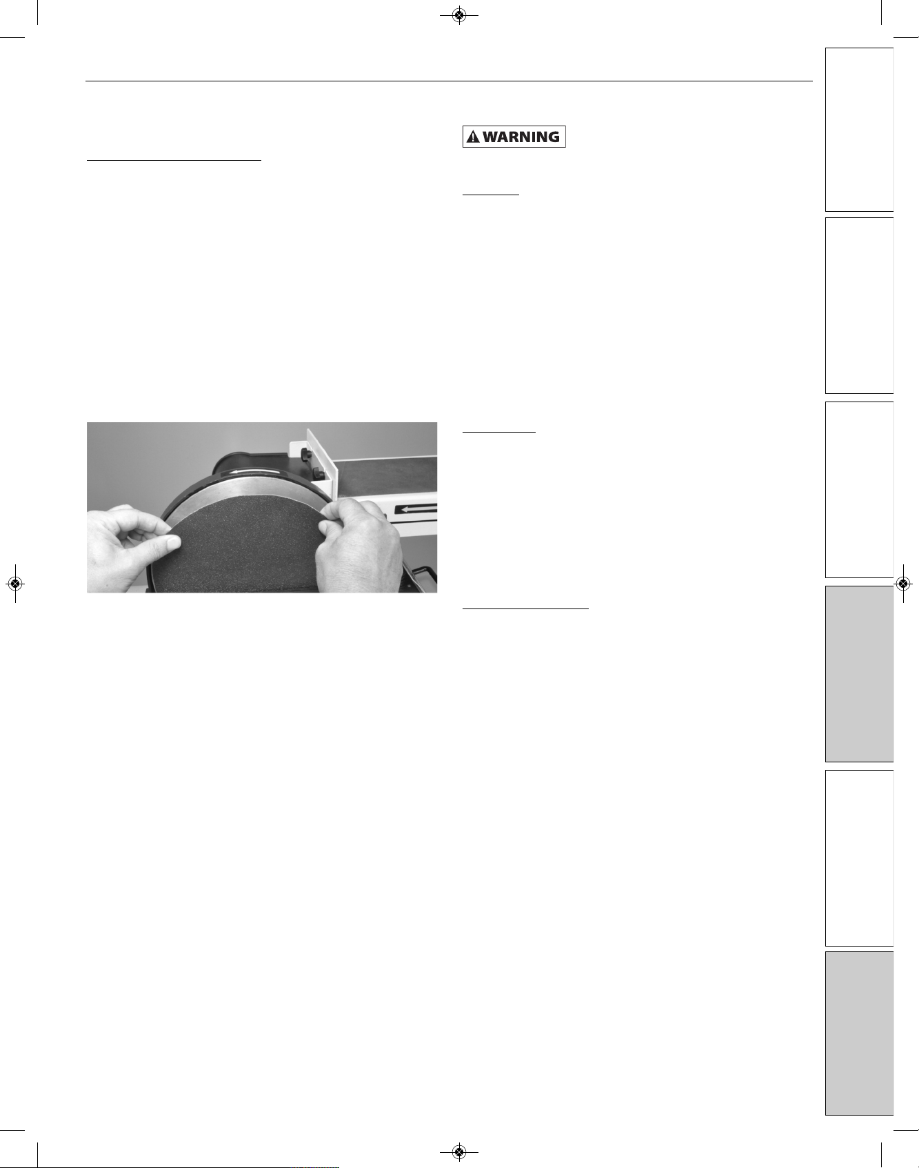
Mounting PSA Sandpaper Disc
NOTE: The 6 x 9˝ Belt Disc Sander only uses 9˝ diameter abrasive
sanding discs with Pressure Sensitive Adhesive (PSA) backing. To
apply the sandpaper:
1. The metal disc plate is pre-installed on the machine. Locate the
9˝ PSA sandpaper disc and peel the protective backing off.
2. Center the sandpaper over the metal disc plate, then press the
sandpaper firmly in place. See Figure 6.
See page 9 for instructions on changing the sandpaper disc.
Before plu in in and turnin on the
machine, mount the sander and complete
all of the adjustments in the instructions that follow. This
will ensure that the sander is correctly set up for safe and
efficient operation.
I STALLATIO
The machine must not be plu ed in and
the power switch must be in the off
position until all adjustments are complete.
Mount Sander
NOTE: Although compact, the sander is heavy. At least two people
are required to lift from carton.
Choose a suitable location to mount the sander. The sander must
be installed in a place with ample lighting and correct power supply.
Make sure there is plenty of room for moving the workpiece. There
must be enough room that neither operators nor bystanders will
have to stand in line with the wood while using the tool. Allow room
so that belt assembly can be positioned horizontally.
Figure 7 shows the base dimensions, mounting holes and required
space to allow for table assembly and belt assembly in horizontal
position.
The sander must be bolted to a firm, level surface. Sander can be
installed on a workbench or a tool stand using bolts, lock washers
and hex nuts (not supplied).
6
GE ING S AR ED
SAFE Y / SPECIFICA IONS
ASSEMBLY / INS ALLA ION
OPERA ION
ROUBLESHOO ING
MAIN ENANCE / REPAIR
NO SE Operating Manual & Parts List 9681115
Figure 7 – Base dimension and required space.
171⁄2˝18˝
12˝
21˝
30˝
3/8˝
Dia.
81⁄2˝
Figure 5
Figure 6 - Mount sandpaper disc.
Lock Handle
Washer
9681115_oipm_En012_9643069.01 0518 05/22/18 Page 6

I STALLATIO (CO TI UED)
Adjusting Disc Table Angle
Ensure sander is disconnected from the power supply prior to
commencing work.
1. To check the trueness of the 90º angle of the disc sanding
table, place a square or other measuring device on the table
with the other end against the sanding disc. See Figure 8.
2. Loosen the disc table adjustment handle, and adjust table
angle to 90º.
3. Re-tighten the disc table adjustment handle.
4. Adjust the angle scale pointer to 0°.
5. To adjust the disc table to another angle, loosen the disc table
adjustment handle.
6. Set the table at the desired angle using the angle scale pointer.
7. Re-tighten the disc table adjustment handle.
To avoid jammin the work piece or
fin ers between the table and sandin
surface, the table ed e should be set to a maximum of 1/16
inches away from sandin surface. See Fi ure 9.
Adjusting Belt Assembly Position
The sanding belt frame can be easily adjusted from a horizontal
position to a vertical position, or any other position to assist your
sanding operation.
1. Loosen the hex screw that pulls the split casting together. This
allow the sanding belt frame to be moved to the work angle
desired. See Figure 10.
2. Once the sanding belt frame is at the desired work angle, re-
tighten the hex screw to secure it in place.
3. In the horizontal position, there are two vertical padded hex
screws that support the sanding belt frame. These should be
checked and adjusted, if necessary, to make sure that they both
touch the sanding belt frame supports. These screws will help
relieve pressure on the casting during work. See Figure 11.
7
NO SE Operating Manual & Parts List 9681115
GE ING S AR ED SAFE Y / SPECIFICA IONS ASSEMBLY / INS ALLA ION OPERA ION ROUBLESHOO ING MAIN ENANCE / REPAIR
Figure 8 - Check disc trueness.
Figure 9
1/16˝
Figure 10
Figure 11
Sanding belt
frame supports.
Hex Screw
9681115_oipm_En012_9643069.01 0518 05/22/18 Page 7

I STALLATIO (CO TI UED)
All electrical connections must be
performed by a qualified electrician.
Power Source
Connect sander to a supply circuit protected by a circuit breaker or
time-delay fuse.
The motor is designed for operation on the voltage and frequency
specified. Normal loads will be handled safely on voltages not more
than 10% above or below the specified voltage.
Running the unit on voltages which are not within the range may
cause overheating and motor burn-out. Heavy loads require that
the voltage at motor terminals be no less than the voltage specified.
Power supply to the motor is controlled by a single pole locking
rocker switch. Remove the key to prevent unauthorized use.
Grounding Instructions
Improper connection of equipment
roundin conductor can result in the risk
of electrical shock. Equipment should be rounded while in
use to protect operator from electrical shock.
Check with a qualified electrician if grounding instructions are not
understood or if in doubt as to whether the tool is properly
grounded.
This tool is equipped with an approved 3-conductor cord rated at
300V and a 3-prong grounding type plug (See Figure 15) for your
protection against shock hazards.
rounding plug should be plugged directly into a properly installed
and grounded 3- prong grounding-type receptacle, as shown
(Figure 12).
Do not remove or alter grounding prong in any manner. In the event
of a malfunction or breakdown, grounding provides a path of least
resistance for electrical shock.
Do not permit fin ers to touch the
terminals of plu when installin or
removin from outlet.
Plug must be plugged into matching outlet that is properly installed
and grounded in accordance with all local codes and ordinances.
Do not modify plug provided. If it will not fit in outlet, have proper
outlet installed by a qualified electrician.
Inspect tool cords periodically, and if damaged, have repaired by an
authorized service facility.
reen (or green and yellow) conductor in cord is the grounding
wire. If repair or replacement of the electric cord or plug is
necessary, do not connect the green (or green and yellow) wire to a
live terminal.
Where a 2-prong wall receptacle is encountered, it must be
replaced with a properly grounded 3-prong receptacle installed in
accordance with National Electric Code and local codes and
ordinances.
This work should be performed by a
qualified electrician.
A temporary 3-prong to 2-prong grounding adapter (See Figure 13)
is available for connecting plugs to a two pole outlet if it is properly
grounded.
Do not use a 3-prong to 2-prong grounding adapter unless
permitted by local and national codes and ordinances.
(A 3-prong to 2-prong grounding adapter is not permitted in
Canada.) Where permitted, the rigid green tab or terminal on the
side of the adapter must be securely connected to a permanent
electrical ground such as a properly grounded water pipe, a
properly grounded outlet box or a properly grounded wire system.
Many cover plate screws, water pipes and outlet boxes are not
properly grounded. To ensure proper ground, grounding means
must be tested by a qualified electrician.
Extension Cords
• The use of any extension cord will cause some drop in voltage
and loss of power.
• Wires of the extension cord must be of sufficient size to carry
the current and maintain adequate voltage.
• Use the table to determine the minimum wire size (A.W. .)
extension cord.
• Use only 3-wire extension cords having 3-prong grounding
type plugs and 3-pole receptacles which accept the tool plug.
• If the extension cord is worn, cut or damaged in any way,
replace it immediately.
Extension Cord Length
Length Wire Size A.W.G.
Up to 25 ft 18
25 – 50 ft 16
NOTE: Using extension cords over 50 ft. long is not
recommended.
8
GE ING S AR ED
SAFE Y / SPECIFICA IONS
ASSEMBLY / INS ALLA ION
OPERA ION
ROUBLESHOO ING
MAIN ENANCE / REPAIR
NO SE Operating Manual & Parts List 9681115
Figure 12 – 3-Prong receptacle
Properly grounded outlet.
rounding Prong
3-Prong Plug
Figure 13 – 2-Prong receptacle with adapter
rounding Lug
Adapter
3-Prong Plug 2-Prong
Receptacle
Make sure this is
connected to a known
grounded receptacle.
9681115_oipm_En012_9643069.01 0518 05/22/18 Page 8

OPERATIO
Operation of any power tool can result in
forei n objects bein thrown into eyes
which can result in severe eye dama e. Always wear safety
o les complyin with United States ANSI Z87.1 before
commencin power tool operation. Safety o les are
available throu h your Grain er catalo .
Always observe the followin safety
precautions:
• Whenever adjusting or replacing any parts on the tool, turn
switch off and remove the plug from power source.
• Recheck table handles and bolt. They must be tightened
securely.
• Make sure all guards are properly attached and securely
fastened.
• Make sure all moving parts are free and clear of any
interference.
• Make sure all fasteners are tight and have not vibrated loose.
• With power disconnected, test operation by hand to verify
clearance and adjust if necessary.
• Always wear eye protection or face shield.
• Make sure abrasive belt tracks properly. Correct tracking gives
optimum performance.
• After turning switch on, always allow belt to come up to full
speed before sanding or grinding.
• Be sure disc turns counterclockwise. Abrasive belt must travel
downward.
• Keep your hands clear of abrasive belt, disc and all moving
parts.
• For optimum performance, do not stall motor or reduce speed.
Do not force the work into the abrasive belt or disc.
• Always support workpiece with table or work stop when
sanding with belt and with table when sanding with disc.
• Never push a sharp corner of workpiece rapidly against belt or
disc. Abrasive backing may tear.
• Replace abrasive belt or disc when they become loaded
(glazed) or frayed.
Before turnin on the machine, review all
safety precautions. Make sure that you
fully understand the features, adjustments and capabilities
of the machine that are outlined throu hout this manual.
O /OFF Switch
The ON/OFF locking switch needs to have the safety switch key
inserted before the switch can be used. This feature prevents
unauthorized use of the sander. See Figure 14.
Abrasive Belt Sanding
• Finishing flat surfaces: Hold workpiece firmly with both hands;
keep fingers away from abrasive belt.
Use table to position and secure work being sanded. Keep end
butted against table and move work evenly across abrasive
belt.
• Finishing long pieces: Use belt in horizontal position with work
stop. Apply only enough pressure to allow abrasive belt to
remove material.
Use work stop to position and secure work being sanded.
Keep end butted against work stop and move work evenly
across abrasive belt. Use extra caution when finishing very thin
pieces.
• Finishing curved edges: Finish outside curves on flat portion of
abrasive belt. Finish inside curves on idler drum portion of
abrasive belt.
• Finishing end grain: It is more convenient to finish ends of long
workpieces with the abrasive belt in a vertical position.
Position table on belt side of sander. Move work evenly across
abrasive belt. For accuracy, use miter gauge. Table may be
tilted for beveled work.
Abrasive Disc Sanding
• Abrasive disc sanding is well suited for finishing small flat
surfaces and convex edges.
• Move workpiece across down side (left) of abrasive disc. Hold
workpiece firmly with both hands; keep fingers away from
abrasive disc.
• Abrasive disc moves fastest and removes more material at
outer edge.
• For accuracy, use miter gauge.
9
NO SE Operating Manual & Parts List 9681115
GE ING S AR ED SAFE Y / SPECIFICA IONS ASSEMBLY / INS ALLA ION OPERA ION ROUBLESHOO ING MAIN ENANCE / REPAIR
Figure 14 - Remove safety key to prevent sander use.
9681115_oipm_En012_9643069.01 0518 05/22/18 Page 9
OPERATIO (CO TI UED)
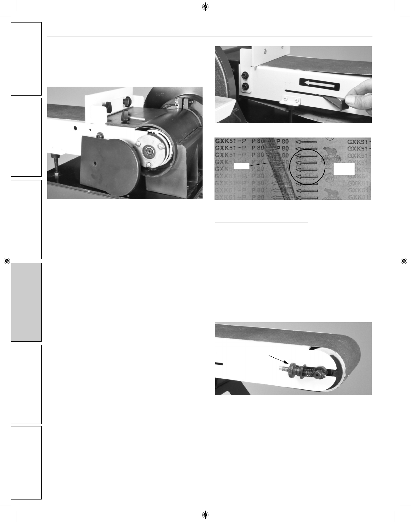
Changing the Sanding Belt
1. Remove the plastic side cover from the frame by unscrewing
the knob. See Figure 15.
2. Remove the small fence. See page 3 for instructions on
installing this part.
3. Slide tension lever to the right to release the belt tension. See
Figure 16.
NOTE: Above the tension lever, there is a direction arrow. The
sanding belt must run in the direction of this arrow so that the splice
does not come apart. See figures 16 and 17.
4. Remove the old belt by sliding it off to the left of the frame.
Place the new sanding belt over the drums with the direction
arrow pointing in the proper direction. See Figure 17. Make
sure the belt is centered on both drums.
5. Slide the tension lever to the left to apply tension to the belt.
See Figure 16.
6. Re-install the small fence and side cover onto the frame
(removed in Step 1 & 2).
7. Plug in the power cord. Turn the switch “ON” and note if the
belt tends to move to the right or left on the drums. The belt
should be running on the center of the drive drums. If it is not,
the belt tracking needs adjustment. See instructions on
sanding belt tracking.
Adjusting Sanding Belt Tracking
Refer to Figure 18.
1. Belt tracking on the center of the drive wheels is pre-set at the
factory. If an adjustment needs to be made, the sander must
be turned on.
a) If the sanding belt moves toward the disc, slowly turn the
tracking knob clockwise 1/4 turn.
b) If the sanding belt moves away from the disc, turn the
tracking knob slowly counterclockwise 1/4 turn.
2. Slowly turn the belt tracking knob noting the belt movement.
Re-adjust the tracking knob, as necessary, until the belt runs
true in the center of the drums.
10
GE ING S AR ED
SAFE Y / SPECIFICA IONS
ASSEMBLY / INS ALLA ION
OPERA ION
ROUBLESHOO ING
MAIN ENANCE / REPAIR
NO SE Operating Manual & Parts List 9681115
Figure 15
Figure 16
Figure 18
Figure 17
Direction
Arrows
Splice
Belt Tracking
Knob
9681115_oipm_En012_9643069.01 0518 05/22/18 Page 10
OPERATIO (CO TI UED)
Changing the Sanding Disc
Refer to Figure 19.
The sandpaper disc can be removed with the table installed, or with
the table removed to give more working access to the disc, if
needed.
1. Peel the used abrasive disc from the metal disc plate. A putty
knife may help in this process.
2. Make sure that the disc plate is clean of any residue. Mineral
spirits will soften the PSA adhesives for its removal. Rotate the
disc by hand to access to all of the disc surface.
3. Peel the protective backing from the new PSA 9˝ abrasive
sanding disc, then center and press the sanding disc firmly
onto the metal disc plate. See page 4.
4. Replace the sanding table if it was removed.
MAI TE A CE
Make certain that the unit is
disconnected from power source before
attemptin to service or remove any component.
Cleaning
• Keep machine and workshop clean. Do not allow sawdust to
accumulate on the tool.
• Keep the drums clean. Dirt on drums will cause poor tracking
and belt slippage.
• Operate tool with dust collector to keep dust from
accumulating.
• Be certain motor is kept clean and is frequently vacuumed free
of dust.
• Use soap and water to clean painted parts, rubber parts and
plastic guards.
Lubrication
The shielded ball bearings in this tool are permanently lubricated at
the factory. They require no further lubrication.
• When operation seems stiff, a light coat of paste wax applied to
the belt and disc tables will make it easier to feed the work
while finishing.
• Do not apply wax to the belt platen. Belt could pick up wax and
deposit it on the drums causing belt to slip.
Keep Tool in Repair
• If power cord is worn, cut or damaged in any way, have it
replaced immediately.
• Replace worn abrasives when needed.
• Replace any damaged or missing parts. Use parts list to order
parts.
• Any attempt to repair motor may create a hazard unless repair
is done by a qualified service technician.
11
NO SE Operating Manual & Parts List 9681115
GE ING S AR ED SAFE Y / SPECIFICA IONS ASSEMBLY / INS ALLA ION OPERA ION ROUBLESHOO ING MAIN ENANCE / REPAIR
Figure 19
9681115_oipm_En012_9643069.01 0518 05/22/18 Page 11
12
GE ING S AR ED
SAFE Y / SPECIFICA IONS
ASSEMBLY / INS ALLA ION
OPERA ION
ROUBLESHOO ING
MAIN ENANCE / REPAIR
NO SE Operating Manual & Parts List 9681115
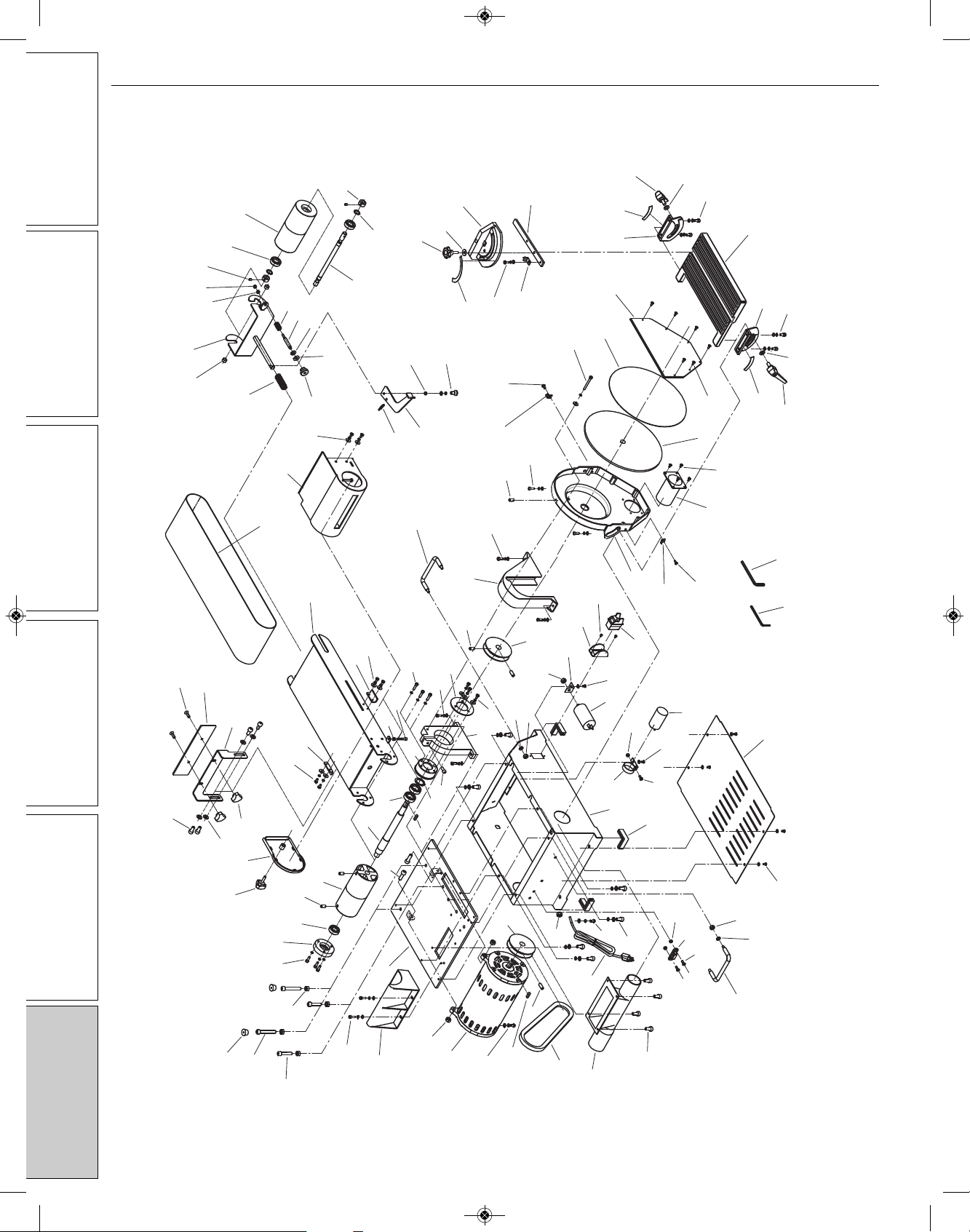
REPAIR PARTS ILLUSTRATIO FOR 9681115 6˝ X 9˝ BELT/DISC SA DER
18
49
16
15
13
12
11
8
9
14
10
6
2
4
16
105
106
90
89
107
104
7
2
25 82
11
48
47
46
61
49
32
50
26
43
89
107
19
44
939
90 71
70
72
108
45
51
51
52
53
41
43 66
58
67
68
69
76
62
63 64
32 65 74
21
77
78
96
80
73
43
43
55
78
28
58
57 56
54
60
42
59
19
61 20
21 22
23
24
79
81
84
91
33
101
22
38
16
92
93
94
2
36
2
1
3
32
35
30
29
31
28
19
99
101
33
100
33
98 33
86 85
34
17
5
102
103
95 88 87
5
17
34
40
97
83
Figure 26 - Parts Illustration
9681115_oipm_En012_9643069.01 0518 05/22/18 Page 12
13
NO SE Operating Manual & Parts List 9681115
GE ING S AR ED SAFE Y / SPECIFICA IONS ASSEMBLY / INS ALLA ION OPERA ION ROUBLESHOO ING MAIN ENANCE / REPAIR
REPAIR PARTS LIST FOR 9681115 6˝ X 9˝ BELT/DISC SA DER
Ref. Part
o. Description o. Qty.
Ref. Part
o. Description o. Qty.
(∆) Not shown.
(*) Standard hardware item, available locally.
(NA) Not available as replacement part.
1 Philips screw + flat washer M4x6 * 4
2 Philips screw + spring washer + flat washer M4x8 * 4
3 Base Plate 9642862.01 1
4 Philips Screw M5x8 * 4
5 Lock handle 9642863.01 2
6 Power Cord 9624671.01 1
7 Dust hose 9642864.01 1
8 V-belt A580 9642865.01 1
9 Hex screw M6X8 * 5
10 Cord clip 6P4 * 1
11 Key A5X15 * 2
12 Motor 9624652.01 1
13 Nut M8 * 2
14 Driving pulley 9624653.01 1
15 Dust cover 9624637.01 1
16 Hex screw + spring washer + flat washer M5x10 * 10
17 Flat washer D8 * 2
18 Hex screw M8X55 * 2
19 Hex nut, I type M8 * 5
20 Bearing cap 9624631.01 1
21 Ball bearing 6201 * 3
22 Hex screw M8X12 * 3
23 Driving drum 9621434.01 1
24 Driving shaft 9624633.01 1
25 Supporting plate NA 1
26 Hex screw + spring washer + flat washer M8X30 * 2
27 Hex screw M8X16 * 4
28 Base NA 1
29 Rubber foot 9624672.01 4
30 Philips screw M5x12 * 1
31 Capacitor bracket 9642866.01 1
32 Hex nut, I type M5 * 3
33 Philips screw M4x10 * 11
34 Hex screw + spring washer + flat washer M6x12 * 4
35 Capacitor 20UF/125V 9642867.01 1
36 Capacitor 20UF/300V 9642868.01 1
37 Capacitor bracket 9642869.01 1
38 Hex screw + spring washer + flat washer M5x18 * 2
39 Belt cover 9624638.01 1
40 Disc table 9642870.01 1
41 Dust port 9642871.01 1
42 Philips screw + spring washer M5x25 * 3
43 Philips screw + spring washer + flat washer M5X12 * 9
44 Idler pulley 9624666.01 1
45 Fixing ring 9642872.01 1
46 Belt frame assembly base 9642873.01 1
47 Bearing cap 9624639.01 1
48 Ball bearing 6202 * 2
49 Hex screw M8x30 * 3
50 Hex screw M5x30 * 1
51 Supporting plate 9642874.01 2
52 Platen 9624628.01 1
53 Sanding belt (6 x 48") 9622173.00 1
54 Philips screw, M6x14 * 2
55 Fence 9642875.01 1
56 Fence support 9642876.01 1
9681115_oipm_En012_9643069.01 0518 05/22/18 Page 13

14
GE ING S AR ED
SAFE Y / SPECIFICA IONS
ASSEMBLY / INS ALLA ION
OPERA ION
ROUBLESHOO ING
MAIN ENANCE / REPAIR
NO SE Operating Manual & Parts List 9681115
REPAIR PARTS LIST FOR 9681115 6˝ X 9˝ BELT/DISC SA DER (CO TI UED)
Ref. Part
o. Description o. Qty.
Ref. Part
o. Description o. Qty.
(∆) Not shown.
(*) Standard hardware item, available locally.
(N/A) Not available as replacement part.
57 Locking nut 9642877.01 2
58 Flat washer M8 * 5
59 Rubber foot 9642878.01 2
60 Dust port cover 9642879.01 1
61 Philips screw + spring washer M5x16 * 3
62 Tension spring 9621426.01 1
63 Bushing 9642880.01 2
64 Driven drum support 9642881.01 1
65 Nut M5 * 1
66 Belt tracking knob M8 9642882.01 1
67 Rubber washer 9642883.01 1
68 Adjustment rod 9642884.01 1
69 Adjustment spring 9642885.01 1
70 Spring Ⅱ9642886.01 1
71 Belt tension handle 9621428.01 1
72 Powder metal bushing 9642887.01 1
73 Position ring for driven shaft 9642888.01 2
74 Inner hex position screw M5X6 9642889.01 2
75 Spring washer for shaft M12 * 2
76 Driven shaft 9642890.01 1
77 Driven drum 9642891.01 1
78 Miter gauge knob 9642892.01 2
79 Miter gauge label 9642893.01 1
80 Miter gauge 9642894.01 1
81 Philips screw + spring washer + flat washer M5x8 * 1
82 Philips screw M8x25 * 2
83 Slide bar 9642895.01 1
84 Miter gauge pointer 9642896.01 1
85 Disc table left support 9642897.01 1
86 Left scale 9642898.01 1
87 Right scale 9642899.01 1
88 Disc table right support 9642900.01 1
89 Spring washer M6 * 4
90 Handle 9642901.01 2
91 Inner hex head screw M5X56 9642902.01 1
92 Switch guard 9642903.01 1
93 Star-head screw M3x10 * 2
94 Switch with key 9642904.01 1
95 Disc guard 9642905.01 1
96 Big washer M6 * 1
97 Sanding disc, 9" PSA 80 rit 9616731.00 1
98 Aluminum disc plate 9621446.01 1
99 Disc cover 9630671.01 1
100 Adapter 9642906.01 1
101 Pointer 9642907.01 2
102 Hex wrench S=4 NA 1
103 Hex wrench NA 1
104 Clip 9642908.01 1
105 Hex nut M5 * 2
106 Philips screw M5x10 * 2
107 Hex nut M6 * 4
108 Philips screw + outer tooth washer + flat washer M5x16 * 1
9681115_oipm_En012_9643069.01 0518 05/22/18 Page 14

15
NO SE Operating Manual & Parts List 9681115
GE ING S AR ED SAFE Y / SPECIFICA IONS ASSEMBLY / INS ALLA ION OPERA ION ROUBLESHOO ING MAIN ENANCE / REPAIR
TROUBLESHOOTI G GUIDE
Symptom Possible Cause(s) Corrective Action
Motor will not start
Motor will not start; fuses blown
or circuit breakers tripped
Motor fails to develop full power
(power output of motor de-
creases rapidly with decrease in
voltage at motor terminals)
Motor overheats
Motor stalls
(resulting in blown fuses or
tripped circuit breakers)
Machine slows down while
operating
Abrasive belt runs off top wheel
1. Blown line fuse or tripped circuit
breaker
2. Low line voltage
3. Defective switch
4. Defective, blown capacitor
1. Overloading due to binding
2. Defective plug
3. Defective cord
4. Defective switch
5. Faulty internal wiring
1. Power line overloaded with lights,
appliances and other motors
2. Undersized wires or circuits too long
3. eneral overloading of power
company’s facilities
Motor overloaded
1. Short circuit in motor or loose
connections
2. Low voltage
3. Incorrect fuses or circuit breakers in
power line
4. Motor overloaded
1. Applying too much pressure to
workpiece
2. V-belt slipping
Not tracking properly
1. If fuse is blown, replace with fuse of proper size.
If breaker tripped, reset it
2. Check power supply for voltage and correct as
needed
3. Replace switch
4. Replace capacitor
1. Clean around wheels and shaft and/or replace
bearings
2. Replace plug
3. Replace cord
4. Replace switch
5. Contact authorized NORSE Service Center
1. Reduce load on power line
2. Increase wire sizes, or reduce length of wiring
3. Request a voltage check from power company
Reduce load on motor
1. Inspect connections in motor for loose or
shorted terminals or worn insulation on lead
wires
2. Correct the low line voltage conditions
3. Install correct fuses or circuit breakers
4. Reduce load on motor
1. Ease up on pressure
2. Increase V-belt tension
See operation section “Adjusting Sanding Belt
Tracking”, page 8.
9681115_oipm_En012_9643069.01 0518 05/22/18 Page 15

ORSE Warranty
NO SE by C.H. Hanson warrants their products to be free of defects in material or workmanship. This
warranty does not cover defects due directly or indirectly to misuse, abuse, normal wear and tear, failure
to properly maintain the product, heated, ground or otherwise altered, or used for a purpose other than
that for which it was intended.
The warranty does not cover expendable and/or wear part (i.e. v-belts, screws, abrasives, jaws), damage to
tools arising from alteration, abuse or use other than their intended purpose, packing and freight. The
duration of this warranty is expressly limited to the terms noted below beginning from the date of
delivery to the original user.
The NO SE branded items carry the following warranties on parts:
All NO SE branded Tools and Accessories 1 YEA
The obligation of NO SE by C.H. Hanson is limited solely to the repair or replacement, at our option, at its
factory or authorized repair agent of any part that should prove inoperable. Purchaser must lubricate and
maintain the product under normal operating conditions at all times. Prior to operation become familiar
with product and the included materials, i.e. warnings, cautions and manuals.
Failure to follow these instructions will void the warrant .
This warranty is the purchaser's exclusive remedy against C. H. Hanson for any inoperable parts in its
product. Under no circumstances is C. H. Hanson liable for any direct, indirect, incidental , special or
consequential damages including loss of profits in any way related to the use or inability to use our
products. This warranty gives you specific legal rights which may vary from state to state.
SERVICE & REPAIR
1. If a NO SE product requires a repair or warranty service DO NOT return the product to
the place of purchase.
2. All warranty related work must be evaluated and approved by NO SE.
3. Prior to returning any item the user must obtain factory approval and a valid GA number.
4. For instructions and GA number call toll free (800) 827-3398.
NORSE - a C.H. Hanson brand
2000 N. Aurora Rd., Naperville, IL 60563 U.S.A.
or call: 1-800-827-3398
NO SE Operating Manual & Parts List 9681115
18-0307
NORSE - a C.H. Hanson brand
2000 N. Aurora Rd., Naperville, IL 60563 U.S.A.
or call: 1-800-827-3398
9681115_oipm_En012_9643069.01 0518 05/22/18 Page 16
Table of contents
Other CH Hanson Sander manuals


