CH Hanson Norse 49G990B User manual

Operating Manual & Parts List
9681121
6 × 9˝
Belt and Disc
SANDER
with Stand
Read carefully and follow all safety
rules and operating instructions before
first use of t is product.
9644210.01-0519

Model #: ___________________
Serial #: ____________________
Purch. Date: ________________

GETTING STARTED
Structural Requirements
Make sure all supporting structures and load attaching devices are
strong enough to hold your intended loads. If in doubt, consult a
qualified structural engineer.
Electrical Requirements
The motor is designed for operation on the voltage and frequency
specified. Normal loads will be handled safely on voltages not more
than 10% above or below the specified voltage.
Running the unit on voltages which are not within the range may
cause overheating and motor burn-out. eavy loads require that
the voltage at motor terminals be no less than the voltage specified.
Tools Needed
Standard mechanic’s hand tool set.
DESCRIPTION
NORSE Belt & Disc Sander/Grinder is used for grinding, deburring,
squaring, polishing and finishing metals, woods and plastics. The
Belt & Disc Sander/Grinder has a totally enclosed, fan-cooled direct
drive motor, fully adjustable tool rests and OS A compliant safety
guards. Belt housing swivels from vertical to horizontal for grinding
long workpieces features and a quick release belt tension and
tracking mechanism.
UNPACKING
Check for shipping damage. If damage has occurred, a claim must
be filed with the carrier immediately. Check for completeness.
Immediately report missing parts to dealer.
If you suspect a be t or disc of being
damaged, rep ace it immediate y.
npack
Do not discard packing materials until after machine has been
inspected for damage and completeness. Locate loose parts and
set aside. Refer to Assembly on page 3 for contents list.
Inspect
• After unpacking the unit, carefully inspect for any damage that
may have occurred during transit. Check for loose, missing or
damaged parts. Shipping damage claims must be filed with the
carrier.
• All tools should be visually inspected before use, in addition to
regular periodic maintenance inspections.
• Be sure that the voltage labeled on the unit matches your
power supply.
SAFETY RULES
For your own safety, read operating
instructions manua before operating too .
PROPOSITION 65 WARNING: Some dust created by
using power tools contain chemicals known to the state
of California to cause cancer, birth defects or other
reproductive harm.
Some examples of these chemicals are:
• Lead from lead-based paints
• Crystalline silica from bricks and cement and other masonry
products.
• Arsenic and chromium from chemically treated lumber.
Your risk from these exposures varies, depending on how often you
do this type of work. To reduce your exposure to these chemicals;
work in a well ventilated area and work with approved safety
equipment. Always wear OSHA/NIOSH approved, properly fitting
face mask or respirator when using such tools
Be Prepared for Job
• Wear proper apparel. Do not wear loose clothing, gloves,
neckties, rings, bracelets or other jewelry which may get
caught in moving parts of machine.
• Wear protective hair covering to contain long hair.
• Wear safety shoes with non-slip soles.
• Wear safety glasses complying with United States ANSI Z87.1.
Everyday glasses have only impact resistant lenses. They are
NOT safety glasses.
• Wear face mask or dust mask if operation is dusty.
• Be alert and think clearly. Never operate power tools when
tired, intoxicated or when taking medications that cause
drowsiness.
Prepare Work Area for Job
• Keep work area clean. Cluttered work areas and work benches
invite accidents.
• Do not use power tools in dangerous environments. Do not
use power tools in damp or wet locations. Do not expose
power tools to rain.
• Work area should be properly lighted.
• Proper electrical plug should be plugged directly into properly
grounded, three-prong receptacle.
• Extension cords should have a grounding prong and the three
wires of the extension cord should be of the correct gauge.
• Keep visitors at a safe distance from work area.
• Keep children out of the workplace. Make workshop childproof.
Use padlocks, master switches or remove switch keys to
prevent any unintentional use of power tools.
1

SAFETY RULES (CONTINUED)
Tool Should Be Maintained
• Always unplug tool prior to inspection.
• Consult manual for specific maintaining and adjusting
procedures.
• Keep tool clean for safest operation.
• Remove adjusting tools. Form habit of checking to see that
adjusting tools are removed before turning machine on.
• Keep all parts in working order. Check to determine that the
guard or other parts will operate properly and perform their
intended function.
• Check for damaged parts. Check for alignment of moving
parts, binding of moving parts, breakage of parts, mounting
and any other condition that may affect a tool’s operation.
• Replace worn or damaged cord immediately.
• A guard or other part that is damaged should be properly
repaired or replaced. Do not perform makeshift repairs. (Use
the parts list to order replacement parts.)
• Maintain tools with care. Keep tools sharp and clean for best
and safest performance. Follow instructions for lubricating and
changing accessories.
Know How to se Tool
• Use right tool for job. Do not force tool or attachment to do a
job for which it was not designed.
• Disconnect tool from power when changing accessories such
as grinding wheels, buffing wheels and the like.
• Avoid accidental start-up. Make sure that the switch is in the off
position before plugging in.
• Do not force tool. It will work most efficiently at the rate for
which it was designed.
• Keep hands away from moving parts and grinding surfaces.
• Never leave a tool running unattended. Turn the power off and
do not leave tool until it comes to a complete stop.
• Do not overreach. Keep proper footing and balance.
• Never stand on tool. Serious injury could occur if tool is tipped
over.
• Know your tool. Learn the tool’s operation, application and
specific limitations.
• Use recommended accessories. Understand and obey all
safety instructions supplied with accessories. The use of
improper accessories may cause risk of injury to persons.
• Turn machine off if it jams. Belt or disc jams when it digs too
deeply into workpiece. (Motor force keeps it stuck in the work.)
• Maintain 1/16˝ maximum clearance between tool rest and
abrasive belt/disc.
• andle the workpiece correctly. Whenever possible, use tool
rest to support workpiece during grinding operation. Turn tool
off if it jams.
• Make sure the tool is secured to a steady, flat working surface.
When used with a stand, make sure the stand is bolted to a flat
surface to prevent tipping over.
• Support workpiece with tool rest.
• Clean sanding dust from beneath tool frequently.
SPECIFICATIONS
49G990B
Belt Size 6 × 48˝
Belt Platen Area 71⁄8× 17˝
Belt Drum Dimensions 3 × 61⁄8˝
Belt Table Dimensions 57⁄8× 913⁄16˝
Belt Table Tilts 0 To 60º
Belt Dust Chute Diameter 2˝
Belt Speed 2700 SFPM
Disc Diameter 9˝
Disc Table Dimensions 57⁄8× 1113⁄16˝
Disc Table Tilts 0 to 45º
Disc Dust Chute Diameter 11⁄4˝
Disc Speed 3450 RPM
Base Dimensions 141⁄2× 141⁄2˝
Switch SP, Locking rocker
Motor 1 P, 120/240 V, 9/4.5 Amps
Weight 100 lbs
Shipping Weight 110 lbs
2
ASSEMBLY
Refer to Figures 1, 2 and 6, page 10.
Do not attempt to operate too unti it is
comp ete y assemb ed according to
instructions.
Do not attempt assemb y if parts are
missing. Use this manua to order repair
parts.
Assemble Stand
Refer to Figure 1.
NOTE: Finger tighten bolts and nuts until assembly is complete.
Then tighten all fasteners securely.
1. Install foot by pressing onto all four legs.
2. Attach one top frame to one pair of legs using carriage bolts,
flat washers and hex nuts. Repeat for second pair of legs.
3. Attach one brace to each pair of legs using carriage bolts, flat
washers and hex nuts.)
4. Connect the two leg sets with the two remaining top frames.
Make sure that the square holes in the legs align with the
square holes in the top frame. Also make sure that the slots on
top of the frame members are aligned at each corner. Secure
frames to legs using carriage bolts, flat washers and hex nuts.
5. Attach the two remaining braces by aligning the square holes
in the legs and the braces. Insert carriage bolts, flat washers
and secure with hex nuts.
Mount Sander to Stand
1. Place sander on the stand.
2. Align mounting holes of sander with slots on top frame.
3. Secure sander to stand on all four corners using four 5/16-18 x
2˝ hex head bolts, eight 5/16˝ flat washers and four 5/16-18
hex nuts.
Assemble Disc Table
Refer to Figure 2.
1. Attach disc guard to end shield using three pan head screws,
three flat washers and three lock washers.
2. Remove tape from key and armature. Slide aluminum disc with
abrasive disc onto armature with keyway in disc aligned with
key in armature. Secure disc to armature using set screw.
3. Slide disc dust chute onto disc guard from below the 9˝ disc
with exhaust port to rear of tool. Secure dust chute to disc
guard with two pan head screws.
4. Slide disc table with attached trunnions onto the raised bosses
on each side of disc guard. Mount two handles and flat
washers through trunnions into threaded holes on each side of
disc guard.
5. Locate table in desired position and secure with handles.
6. Be sure the gap between the disc and disc table is 1/16˝ or
less.
7. If adjustment is necessary, loosen set screw in aluminum disc
through the opening at top-rear of disc guard. Position disc
1/16˝ or less from edge of table. Secure disc with set screw.
Assemble Belt Table
Refer to Figure 6, page 10.
Slide belt table assembly (Ref. No. 76) into trunnion groove of pivot
bracket (Ref. No. 47). Mount using socket head bolt and flat
washer (Ref. Nos. 2 and 75). Locate table in desired position. Be
sure that gap between belt table and belt is 1/16˝ or less. Tighten
bolt securely.
3
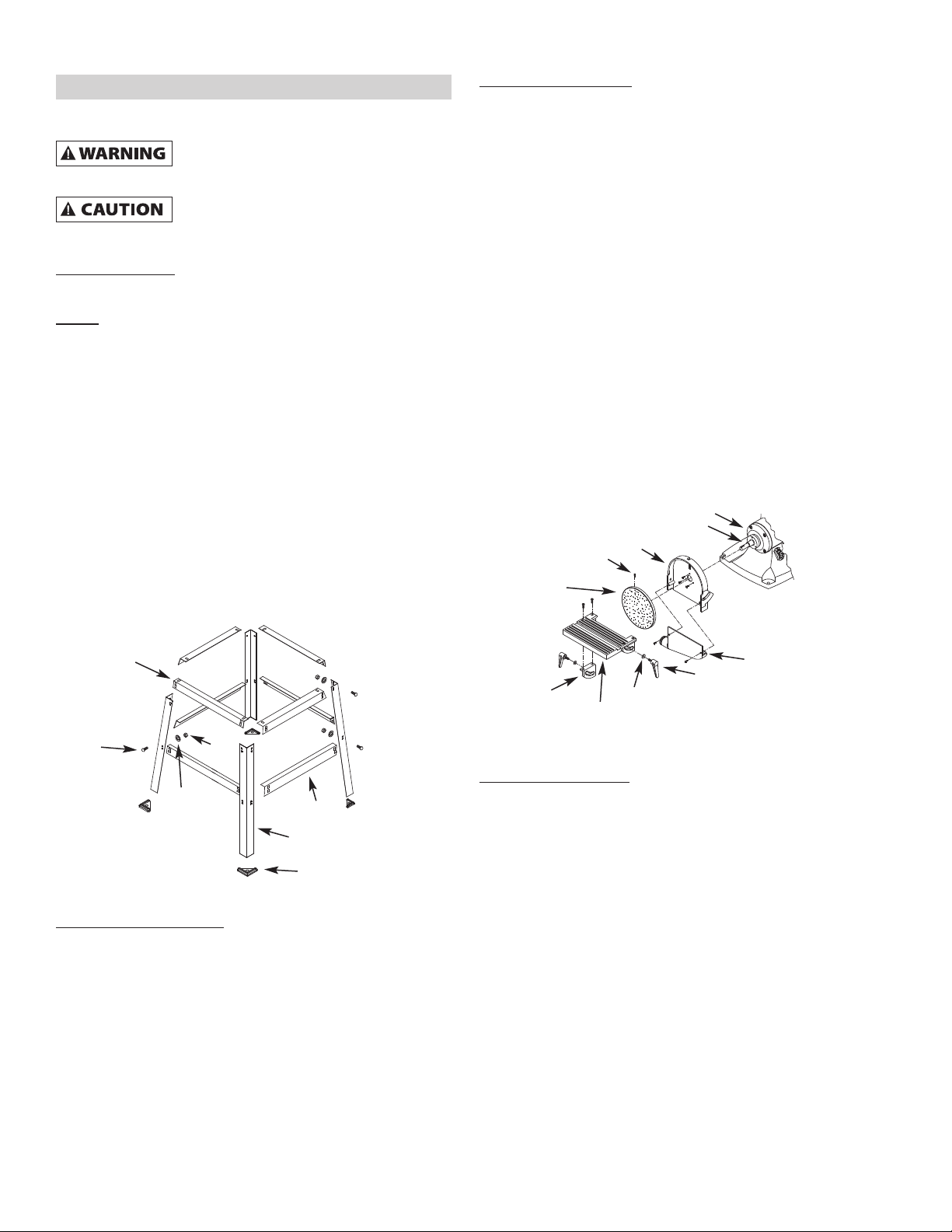
Figure 1 - Assemble stand.
Top Frame
Brace
Leg
Foot
ex
Nut
Flat
Washer
Carriage
Bolt
Figure 2 – Assemble disc table.
End Shield
Flat Washers
Trunnion
Disc Table
Disc Guard
Dust Chute
Set Screw
andle
Armature and Key
Aluminum Disc
with Abrasive
Disc
INSTALLATION
Refer to Figures 3, 4 and 5.
A e ectrica connections must be
performed by a qua ified e ectrician.
Power Source
The motor is designed for operation on the voltage and frequency
specified. Normal loads will be handled safely on voltages not more
than 10% above or below the specified voltage.
Running the unit on voltages which are not within the range may
cause overheating and motor burnout. eavy loads require that
voltage at motor terminals be no less than the voltage specified on
nameplate. Power supply to the motor is controlled by a single pole
locking rocker switch. Remove the key to prevent unauthorized
use.
Grounding Instructions
Improper connection of equipment
grounding conductor can resu t in the risk
of e ectrica shock. Equipment shou d be grounded whi e in
use to protect operator from e ectrica shock.
• Check with a qualified electrician if grounding instructions are
not understood or if in doubt as to whether the tool is properly
grounded.
• This tool is equipped with an approved 3-conductor cord rated
at 300V and a 3-prong grounding type plug (See Figure 3) for
your protection against shock hazards.
• Grounding plug should be plugged directly into a properly
installed and grounded 3-prong grounding-type receptacle, as
shown (Figure 3).
• Do not remove or alter grounding prong in any manner. In the
event of a malfunction or breakdown, grounding provides a
path of least resistance for electrical shock.
Do not permit fingers to touch the
termina s of p ug when insta ing or
removing from out et.
• Plug must be plugged into matching outlet that is properly
installed and grounded in accordance with all local codes and
ordinances. Do not modify plug provided. If it will not fit in
outlet, have proper outlet installed by a qualified electrician.
• Inspect tool cords periodically, and if damaged, have repaired
by an authorized service facility.
• Green (or green and yellow) conductor in cord is the grounding
wire. If repair or replacement of the electric cord or plug is
necessary, do not connect the green (or green and yellow) wire
to a live terminal.
• Where a 2-prong wall receptacle is encountered, it must be
replaced with a properly grounded 3-prong receptacle installed
in accordance with National Electric Code and local codes and
ordinances.
This work shou d be performed by a
qua ified e ectrician.
• A temporary 3-prong to 2-prong grounding adapter (See Figure
4) is available for connecting plugs to a two pole outlet if it is
properly grounded.
• Do not use a 3-prong to 2-prong grounding adapter unless
permitted by local and national codes and ordinances.
(A 3-prong to 2-prong grounding adapter is not permitted in
Canada.) Where permitted, the rigid green tab or terminal on
the side of the adapter must be securely connected to a
permanent electrical ground such as a properly grounded
water pipe, a properly grounded outlet box or a properly
grounded wire system.
• Many cover plate screws, water pipes and outlet boxes are not
properly grounded. To ensure proper ground, grounding means
must be tested by a qualified electrician.
Extension Cords
Use proper extension cord. Make sure your extension cord is in
good condition. When using an extension cord, be sure to use one
heavy enough to carry the current your product will draw. An
undersized cord will cause a drop in line voltage resulting in loss of
power and overheating. Table shows the correct size to use
depending on cord length and nameplate ampere rating. If in doubt,
use the next heavier gage. The smaller the gage number, the
heavier the cord.
4
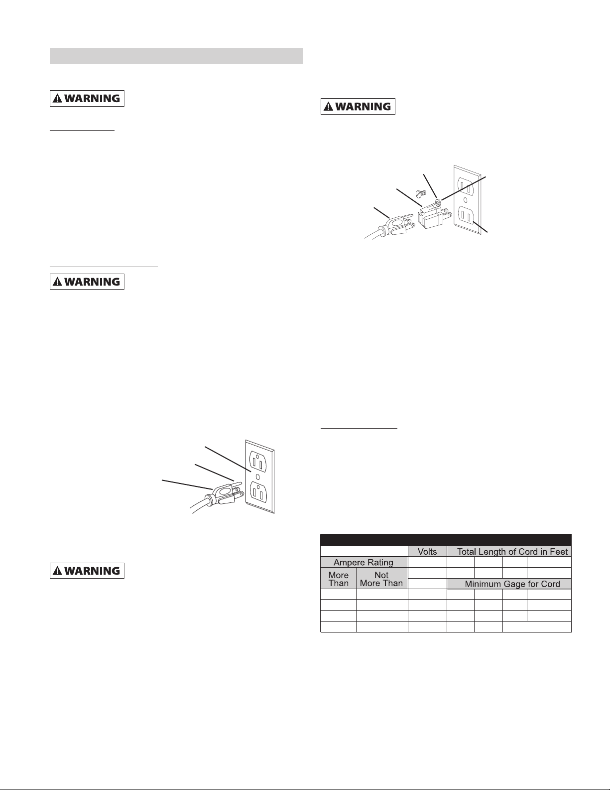
Figure 3 – 3-Prong receptacle.
Properly grounded outlet
Grounding prong
3-Prong plug
Figure 4 – 2-Prong receptacle with adapter.
Grounding lug
Adapter
3-Prong plug
2-Prong receptacle
Make sure this is
connected to a known
grounded receptacle
Volts
120 25 50 100 150
240 50 100 150 300
06 18 16 16 14
6 10 18 16 14 12
10 12 16 16 14 12
12 16 14 12
More Not
Than More Than Minimum Gage for Cord
Total Length of Cord in Feet
Not Recommended
Ampere Rating
Extension Cord Ta le
INSTALLATION (CONTINUED)
Electrical Connections
A e ectrica connections must be
performed by a qua ified e ectrician. Make
sure too is off and disconnected from power source whi e
motor is mounted, connected, reconnected or anytime
wiring is inspected.
• Motor and wires are installed as shown in wiring diagram (See
Figure 5). Motor is assembled with approved, 3-conductor cord
to be used at 120/240 volts. Motor is prewired at the factory for
120 volts.
• To use the grinder with a 240V power supply, have a qualified
electrician rewire motor and attach a 240 volt, 15A three-prong
plug onto grinder line cord.
OPERATION
Operation of any power too can resu t in
foreign objects being thrown into eyes
which can resu t in severe eye damage. A ways wear safety
gogg es comp ying with United States ANSI Z87.1 (shown on
package) before commencing power too operation.
A ways observe the fo owing safety
precautions:
• Whenever adjusting or replacing any parts on the sander turn
power off and remove the plug from power source.
• Recheck tool rest bolts, they must be tightened securely.
• Make sure all guards are properly attached. All guards should
be securely fastened.
• Make sure all moving parts are free and clear of any
interference.
• Make sure all fasteners are tight and have not vibrated loose.
• With power disconnected, test operation by hand for clearance
and adjust if necessary.
• Always wear eye protection or face shield.
• Make sure abrasive belt tracks properly. Correct tracking gives
optimum performance.
• After turning switch on, always allow belt and disc to come up
to full speed before sanding or grinding.
• Abrasive belt must travel towards tool rest.
• Avoid kickback by grinding in accordance with the directional
arrows.
• Keep your hands clear of abrasive belt/disc and all moving
parts.
• For optimum performance do not stall motor or reduce speed.
Do not force the work into the abrasive.
• Support workpiece with tool rest when grinding with belt/disc.
• Never push a sharp corner of workpiece rapidly against
belt/disc. Abrasive backing may tear.
• Replace abrasives when they become loaded (glazed) or
frayed.
• When grinding metal, move workpiece across abrasive to
prevent heat build-up.
• Never attempt wet sanding. If work-piece becomes too hot to
handle, cool it in water.
• Do not expose to rain or use in damp locations.
Replacing Abrasive Belt
Refer to Figure 6, page 10.
Abrasive belt should be replaced when worn, torn, or glazed.
Loosen belt cover knobs (Ref. No. 18) and open belt cover.
1. Release belt tension by pushing tension lever (Ref. No. 35)
towards idler drum. Slide old belt off the idler and drive wheels.
NOTE: There may be an arrow on the inside of the belt. The arrow
should point down toward the belt table to ensure that the splice in
the belt will not come apart.
2. Slide new belt over the drive and idler drums; center belt on
drums.
3. Push tension lever towards drive drum to tension belt.
4. Rotate belt by hand to check tracking. Belt should ride
centered on drive and idler drums. Adjust thumb nut (Ref. No.
29) as needed to center belt on drums. When belt tracks
properly, tighten hex nut. (Ref. No. 28) If adjustment of thumb
nut does not provide desirable tracking, adjust the stud (Ref.
No. 30) using a flat screwdriver. To adjust stud, loosen hex nut
and turn stud counterclockwise to move belt to the right or
clockwise to move belt to the left until belt rides centered on
drive and idler drums. Tighten hex nut while holding the stud in
place.
5. Close belt cover and tighten knobs.
Adjust Belt Assembly Position
Refer to Figure 6, page 10.
Sanding belt assembly can be adjusted from horizontal to vertical
position.
1. Loosen socket head bolt (Ref. No. 37 is threaded into pivot
bracket.
2. Tilt belt assembly to desired position (from horizontal to
vertical). Secure belt assembly position by tightening socket
head bolt in pivot bracket.
5
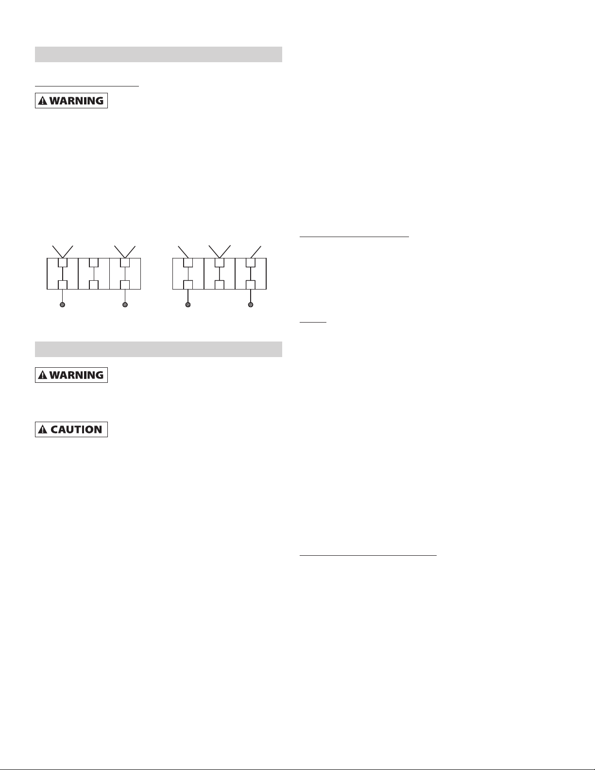
Blue Red Blue
White RedBrown White
120V
Brown
240V
Figure 5 – Wiring diagram.

OPERATION (CONTINUED)
Adjust Belt Table
Refer to Figure 6, page 10.
1. To adjust belt table angle, loosen socket head bolt (Ref. No.
75).
2. Tilt belt table to desired position. Adjust for 1/16˝ maximum
clearance between the belt and the table. Secure by tightening
socket head bolt.
Horizontal Belt Sanding
Refer to Figure 6, page 10.
The belt platen can be tilted from a vertical to a horizontal position.
1. Remove the belt table by removing the socket head bolt and
flat washer (Ref. Nos. 2 and 75). Loosen the socket head bolt
(Ref. No. 37) in the pivot bracket; tilt the belt platen assembly to
the horizontal position and tighten the socket head bolt to
secure position.
Work Stop
Refer to Figure 6, page 10.
The work stop (Ref. No. 74) can be used instead of the belt table.
1. Remove socket head bolt and flat washer (Ref. Nos. 2 and 75)
holding belt table on pivot bracket. Remove belt table.
2. Mount work stop to pivot bracket using the socket head bolt
and washer.
Abrasive Belt Finishing
Excessive force on the be t wi shorten
the ife of the be t and the motor.
• Finishing flat surfaces: old workpiece firmly with both hands;
keep fingers away from abrasive belt.
Use work stop. Work stop is used to position and secure work
being sanded. Keep end butted against work stop and move
work evenly across abrasive belt. Use extra caution when
finishing very thin pieces.
Finishing long pieces: remove work stop. Apply only enough
pressure to allow abrasive belt to remove material.
• Finishing curved edges: Finish outside curves on flat portion of
abrasive belt. Finish inside curves on idler drum portion of
abrasive belt.
• Finishing end grain: It is more convenient to finish ends of long
workpieces with the abrasive belt in a vertical position.
Position table on belt side of sander. Lock into position with
socket head bolt and washer. Move work evenly across
abrasive belt. For accuracy, use miter gauge. Table may be
tilted for beveled work.
Replacing Abrasive Disc
Refer to Figure 6, page 10.
1. Remove disc table and dust chute (Ref. Nos. 4 and 8).
Remove old abrasive disc by peeling it from the aluminum disc.
Removing aluminum disc from motor shaft is not necessary.
2. Clean aluminum disc if necessary. Select the proper abrasive
disc and apply to aluminum disc.
3. Replace dust chute and disc table.
Adjusting Disc Table Angle
Refer to Figure 6, page 10.
Disc table is adjustable from 0 to 45º for beveled work.
1. To adjust the disc table, loosen the two handles (Ref. No. 1)
and pivot to the desired angle.
2. Use the scale on disc table trunnions to set table from 0 to 45º
from abrasive disc.
3. When disc table is at desired angle, lock it into position by
securely tightening the handles.
Abrasive Disc Finishing
Excessive force on the disc wi shorten
the ife of the disc and the motor.
• Abrasive disc sanding is well suited for finishing small flat
surfaces and convex edges.
• Move workpiece across down side (right) of abrasive disc.
• Abrasive disc moves fastest and removes more material at
outer edge.
• For accuracy, use miter gauge.
sing Miter Gauge
• The miter gauge is used on both belt and disc tables. Use the
miter gauge for securing the work and holding the proper angle
while sanding.
• Adjust angle by repositioning the miter gauge scale and locking
it into place with knob.
• Check accuracy of miter gauge scale.
• Use a combination square to adjust miter gauge square to
disc. Indicator should be at zero. Loosen screw and reposition
indicator if necessary.
6

MAINTENANCE
Make certain that the unit is disconnected
from power source before attempting to
service or remove any component.
Cleaning
• Keep machine and workshop clean. Do not allow sawdust to
accumulate on the tool.
• Keep the drums clean. Dirt on drums will cause poor tracking
and belt slippage.
• Operate tool with dust collector to keep dust from
accumulating.
After sanding wood or non-meta ic
materia , a ways c ean dust co ector and
guards of sawdust before grinding meta . Sparks cou d
ignite debris and cause a fire.
• Be certain motor is kept clean and is frequently vacuumed free
of dust.
• Use soap and water to clean painted parts, rubber parts and
plastic guards.
Lubrication
• The shielded ball bearings in this tool are permanently
lubricated at the factory. They require no further lubrication.
• When operation seems stiff, a light coat of paste wax applied to
the belt table and disc table will make it easier to feed the work
while finishing.
• Do not apply wax to the belt platen. Belt could pick up wax and
deposit it on wheels causing belt to slip.
Keep Tool In Repair
• If power cord is worn, cut or damaged, have it replaced
immediately.
• Replace worn abrasives when needed.
• Replace any damaged or missing parts. Use parts list to order
parts.
• Any attempt to repair motor may create a hazard unless repair
is done by a qualified service technician.
7

TROUBLESHOOTING GUIDE
Symptom Possible Cause(s) Corrective Action
8
Motor will not start.
Motor will not start; fuses blown
or circuit breakers tripped.
Motor fails to develop full power
(power output of motor decreases
rapidly with decrease in voltage at
motor terminals).
Motor overheats
Motor stalls
(resulting in blown fuses or
tripped circuit breakers).
Machine slows down while
operating.
Abrasive belt runs off top wheel.
1. Blown line fuse or tripped circuit
breaker.
2. Low line voltage.
3. Defective switch.
4. Defective, blown capacitor.
1. Overloading due to binding.
2. Defective plug.
3. Defective cord.
4. Defective switch.
5. Motor wired for different line voltage.
6. Faulty internal wiring.
1. Power line overloaded with lights,
appliances and other motors.
2. Undersized wires or circuits too long.
3. General overloading of power
company’s facilities.
Motor overloaded
1. Short circuit in motor or loose
connections.
2. Low voltage.
3. Motor wired for different line voltage.
4. Incorrect fuses or circuit breakers in
power line.
5. Motor overloaded.
Applying too much pressure to workpiece.
Not tracking properly.
1. If fuse is blown, replace with fuse of proper
size. If breaker tripped, reset it.
2. Check power supply for voltage and correct as
needed.
3. Replace switch.
4. Replace capacitor.
1. Clean around wheels and shaft and/or replace
bearings.
2. Replace plug.
3. Replace cord.
4. Replace switch.
5. Rewire motors as per line voltage (See
Electrical Connections, page 5).
6. ave a qualified electrician service unit.
1. Reduce load on power line.
2. Increase wire sizes, or reduce length of wiring.
3. Request a voltage check from power
company.
Reduce load on motor.
1. Inspect connections in motor for loose or
shorted terminals or worn insulation on lead
wires.
2. Correct the low line voltage conditions.
3. Rewire motor as per line voltage.
4. Install correct fuses or circuit breakers (See
Electrical Connections, page 5).
5. Reduce load on motor.
Ease up on pressure.
See Operation section “Tracking abrasive belt”.

NOTES
9

10
REPAIR PARTS ILLUSTRATION FOR SANDER
Figure 6 – Replacement parts illustration for sander.

11
1 Star- ead Screw w/ Flat Washer M4x15 * 5
2 Miter Gauge Assembly 9636340.01 1
3 Star- ead Screw w/ Flat Washer M4x8 * 10
4 Base Cover 9616919.01 1
5 Star- ead Screw w/ Washers M4x8 * 1
6 External Teeth Lock Washer M4 * 1
7 Starting Capacitor 200uf/125V 9636349.01 1
8 ex Nut M4 * 4
9 Capacitor Support 9616918.01 1
10 Running Capacitor 20uf/300V 9616639.01 1
11 Capacitor Support 9616918.01 1
12 ex Nut M8 * 1
13 Philips Screw w/ Lock Washer M8x20 * 4
14 Electronic Centrifugal Switch 9643070.01 1
15 Lock Washer M8 * 1
16 ex ead Screw M8x25 * 2
17 Power Cord 9624671.01 1
18 Clip Plate 9608172.01 1
19 Philips Screw M5x8 * 4
20 Cord Clip * 1
21 Switch Plate 9636282.01 1
22 Switch 9608066.01 1
23 Base N/A 1
24 Motor N/A 1
25 ex ead Screw w/ Washers M6x12 * 4
26 Locking Knob 9642863.01 2
27 Flat Washer M8 * 5
28 Work Table Right Support 9642900.01 1
29 Work Table Left Support 9642897.01 1
30 Work Table for Disc 9642870.01 1
31 Star- ead Screw M4x10 * 4
32 Dust Chute 9608372.01 1
33 Sanding Disc, 9", 80 Grit, 1GLB3 * 1
34 ex Position Screw M8x12 * 6
35 Key A5x15 * 1
36 9" Disc Plate 9621446.01 1
37 Star- ead Screw w/ Washers M6x16 * 3
38 Disc Cover 9608371.03 1
39 Pointer 9644128.01 2
40 Philips Screw w/ Washers M5x16 * 1
41 Table Scale 9644129.01 1
42 Belt Worktable 9608387.02 1
43 Guide Block 9644130.01 1
44 Spring Column Pin M4x10 * 2
45 Wire Block 9616899.01 1
46 Pivot Bracket 9636342.01 1
47 Lower Guard 9636339.01 1
48 Philips Screw M5x10 * 4
49 Work Stop 9608381.01 1
50 Spring Column Pin M5x15 * 1
51 Pivot Stop Bracket 9636341.01 1
52 Philips Screw w/ Lock Washer M6x10 * 3
53 Drive Pulley 9621434.01 1
54 Flat Washer M6 * 2
55 ex Screw M6x10 * 2
56 Dust Port 9628678.01 1
57 Knob 9628677.01 2
58 Clamping Pad M5 9631460.01 2
59 Belt Guard 9636337.01 1
60 ex Screw M8x10 * 2
61 ex Screw w/ Flat Washer M8x16 * 5
62 Platen 9608392.01 1
63 Powder Metallurgical Jacket 9644135.01 1
64 Support Rod w/ Bumper 9636344.01 1
65 Support 9636343.01 1
66 Sanding Belt 6" X 48" 80 Grit 5A998 1
67 Tighten Spring 9608397.03 1
68 Bushing 9608403.01 2
69 Idler Drum Bracket 9608396.03 1
70 ex Screw M5 * 3
71 Non-Metallic Insert Nut M5 * 1
72 ex Screw M5x6 * 2
73 Bearing 6201ZZ * 2
74 Idler Drum 9608400.01 1
75 External Circlip M12 * 2
76 Driven Shaft 9608401.01 1
77 Driven Shaft Positioning Sleeve 9608403.01 2
78 Spring 9644131.01 1
79 igh Top Knurled Nut 9644132.01 1
80 Rubber Pad 9644133.01 1
81 Adjusting Screw 9608412.01 1
82 Tension Spring 9644134.01 1
83 Tension andle 9636338.01 1
∆ Owner's Manual 9644210.01 1
Ref.
No. Description Part No. Qty.
Ref.
No. Description Part No. Qty.
Ref.
No. Description Part No. Qty.
REPAIR PARTS LIST FOR SANDER
(∆) Not shown.
(▲) Not included.
(N/A) Not available as replacement part.
(*) Standard hardware item, available locally.

REPAIR PARTS ILLUSTRATION FOR STAND
12
Figure 7 – Replacement parts illustration for stand.
8
2
3
4
9
5
6
7
1

13
REPAIR PARTS LIST FOR STAND
1 Top Frame 9636351.00 4
2 Brace 9636352.00 4
3 Leg 9636353.00 4
4 Foot 9636354.00 4
5 Carriage bolt M6 × 12 * 32
6 Flat washer M8 *8
7 ex Nut M8 *4
8 ex head bolt M8 × 55 *4
9 Flange Nut M6 * 32
Ref. Part
No. Description Number Qty.
(∆) Not shown.
(▲) Not included.
(N/A) Not available as replacement part.
(*) Standard hardware item, available locally.

NO SE Operating Manual & Parts List 9681121
NO SE - a C.H. Hanson brand
2000 N. Aurora d., Naperville, IL 60563 U.S.A.
or call: 1-800-827-3398
NO SE by C.H. Hanson warrants their products to be free of defects in material or workmanship. This
warranty does not cover defects due directly or indirectly to misuse, abuse, normal wear and tear, failure
to properly maintain the product, heated, ground or otherwise altered, or used for a purpose other than
that for which it was intended.
The warranty does not cover expendable and/or wear part (i.e. v-belts, screws, abrasives, jaws), damage to
tools arising from alteration, abuse or use other than their intended purpose, packing and freight. The
duration of this warranty is expressly limited to the terms noted below beginning from the date of
delivery to the original user.
The NO SE branded items carry the following warranties on parts:
All NO SE branded Tools and Accessories 1 YEA
The obligation of NO SE by C.H. Hanson is limited solely to the repair or replacement, at our option, at its
factory or authorized repair agent of any part that should prove inoperable. Purchaser must lubricate and
maintain the product under normal operating conditions at all times. Prior to operation become familiar
with product and the included materials, i.e. warnings, cautions and manuals.
Failure to follow these instructions will void the warrant .
This warranty is the purchaser's exclusive remedy against C. H. Hanson for any inoperable parts in its
product. Under no circumstances is C. H. Hanson liable for any direct, indirect, incidental , special or
consequential damages including loss of profits in any way related to the use or inability to use our
products. This warranty gives you specific legal rights which may vary from state to state.
SERVICE & REPAIR
1. If a NO SE product requires a repair or warranty service DO NOT return the product to
the place of purchase.
2. All warranty related work must be evaluated and approved by NO SE.
3. Prior to returning any item the user must obtain factory approval and a valid GA number.
4. For instructions and GA number call toll free (800) 827-3398.
NORSE WARRANTY
18-0307
Table of contents
Other CH Hanson Sander manuals


Popular Sander manuals by other brands


Sioux Tools
Sioux Tools SPS07P12 Instructions-parts list

Swarts Tools
Swarts Tools SW1871 Instruction booklet and warranty information

Dynabrade
Dynabrade Dynorbital-Spirit 59000 Safety, operation and maintenance

stayer
stayer RO125 operating instructions

stayer
stayer LOM10B operating instructions

Makita
Makita 9046 instruction manual