CH Hanson PALMGREN 9681061C User manual

Operating Manual & Parts List 9681061C
2 x 6"
belt and disc
Sander
Read carefully and follow all safety rules and operating instructions before
first use of this product.
9631694.01-1117

2
Palmgren Operating Manual & Parts List 9681061C
GETTING STARTED
STRUCTURAL REQUIREMENTS
Make sure all supporting structures and load attaching devices are
strong enough to hold your intended loads. If in doubt, consult a
qualified structural engineer.
ELECTRICAL REQUIREMENTS
The power supply to the Sander needs to be 120 volt/ 3.5 amp, sin-
gle phase, 60 Hz. The standard allowable voltage variation is plus or
minus 10%.
TOOLS NEEDED:
Standard mechanic’s hand tool set.
UNPACKING
WARNING: Be careful not to touch overhead power lines, piping,
lighting, etc. if lifting equipment is used. Sander weighs approxi-
mately 32 lbs, proper tools, equipment and qualified personnel
should be employed in all phases of unpacking and installation.
Carton should be handled with care to avoid damage from drop-
ping, bumping, etc. Store and unpack carton with correct side up.
After unpacking Sander, inspect carefully for any damage that may
have occurred during transit. Check for loose, missing or damaged
parts. If any damage or loss has occurred, claim must be filed with
carrier immediately. Check for completeness. Immediately report
missing parts to dealer.
Sander is shipped partially assembled. End user will need to assem-
ble loose parts to machine.
IM ORTANT: The tool has been coated with a protective coating. In
order to ensure proper fit and operation, the coating must be re-
moved. Remove coating with mild solvents such as mineral spirits
and a soft cloth. Nonflammable solvents are recommended. After
cleaning, cover all exposed metal surfaces with a light coating of
oil.
CAUTION: Never use highly volatile solvents. Avoid getting clean-
ing solution on paint as it may tend to deteriorate these finishes.
Use soap and water on painted components.
CONTENTS:
• 2 x 6" Belt and Disc Sander (1)
• Disc table (1)
• Abrasive disc (1)
• Mater gauge assembly (1)
• Belt table (1)
• Parts bag (1) includes: work stop; two knobs; one 10-1.5 x
16mm socket head bolt; one 10mm flat washer; two 6mm wash-
ers; one each 5, 6 and 8mm hex wrenches and one 12mm open
end wrench.
• Operating Instructions and Parts Manual (1)
UN ACK:
•Do not discard packing materials until after machine has been in-
spected for damage and completeness. Locate loose parts and set
aside.
INS ECT:
•After unpacking the unit, carefully inspect for any damage that
may have occurred during transit. Check for loose, missing or dam-
aged parts. Shipping damage claims must be filed with the carrier.
• All tools should be visually inspected before use, in addition to
regular periodic maintenance inspections.
• Be sure that the voltage labeled on the unit matches your
power supply.
SEE GENERAL SAFETY INSTRUCTIONS, CAUTIONS AND
WARNINGS AS SHOWN.
SAFET RULES
WARNING: For your own safety, read all of the instructions and
precautions before operating tool.
RO OSITION 65 WARNING: Some dust created by
using power tools contain chemicals known to the state
of California to cause cancer, birth defects or other repro-
ductive harm.
Some examples of these chemicals are:
• Lead from lead-based paints.
• Crystalline silica from bricks and cement and other masonry
products.
• Arsenic and chromium from chemically-treated lumber.
Your risk from these exposures varies, depending on how often you
do this type of work. To reduce your exposure to these chemicals:
work in a well ventilated area and work with approved safety
equipment. Always wear OSHA/NIOSH approved, properly fitting
face mask or respirator when using such tools.
WARNING: Always follow proper operating procedures as defined
in this manual even if you are familiar with the use of this or similar
tools. Remember that being careless for even a fraction of a second
can result in severe personal injury.
BE RE ARED FOR JOB
• Wear proper apparel. Do not wear loose clothing, gloves, neck-
ties, rings, bracelets or other jewelry which may get caught in
moving parts of machine.
• Wear protective hair covering to contain long hair.
• Wear safety shoes with non-slip soles.
• Wear safety glasses complying with United States ANSI Z87.1.
Everyday glasses have only impact resistant lenses. They are
NOT safety glasses.
• Wear face mask or dust mask if operation is dusty.
• Be alert and think clearly. Never operate power tools when tired,
intoxicated or when taking medications that cause drowsiness.
RE ARE WORK AREA FOR JOB
• Keep work area clean. Cluttered work areas invite accidents.
• Do not use power tools in dangerous environments. Do not use
power tools in damp or wet locations. Do not expose power
tools to rain.
• Work area should be properly lighted.
• Proper electrical receptacle should be available for tool. Three-
prong plug should be plugged directly into properly grounded,
three-prong receptacle.
• Extension cords should have a grounding prong and the three
wires of the extension cord should be of the correct gauge.
• Keep visitors at a safe distance from work area.
• Keep children out of workplace. Make workshop childproof. Use
padlocks, master switches or remove switch keys to prevent any
unintentional use of power tools.
3
Palmgren Operating Manual & Parts List 9681061C
SAFET RULES (CONTINUED)
TOOL SHOULD BE MAINTAINED
• Always unplug tool prior to inspection.
• Consult manual for specific maintaining and adjusting proce-
dures.
• Keep tool lubricated and clean for safest operation.
• Remove adjusting tools. Form habit of checking to see that ad-
justing tools are removed before switching machine on.
• Keep all parts in working order. Check to determine that the
guard or other parts will operate properly and perform their in-
tended function.
• Check for damaged parts. Check for alignment of moving parts,
binding, breakage, mounting and any other condition that may
affect a tool’s operation.
• A guard or other part that is damaged should be properly re-
paired or replaced. Do not perform makeshift repairs. (Use parts
list provided to order repair parts.)
KNOW HOW TO USE TOOL
• Use right tool for job. Do not force tool or attachment to do a
job for which it was not designed.
• Disconnect tool when changing abrasive belt or disc.
• Avoid accidental start-up. Make sure that the tool is in the OFF
position before plugging in.
• Do not force tool. It will work most efficiently at the rate for
which it was designed.
• Use of improper accessories may cause risk of injury to persons.
• Handle workpiece correctly. Protect hands from possible injury.
• Turn machine off if it jams. Belt jams when it digs too deeply
into workpiece. (Motor force keeps it stuck in the work.)
• Never leave tool running unattended. Turn power off and do
not leave tool until it comes to a complete stop.
• Do not overreach. Keep proper footing and balance.
• Never stand on tool. Serious injury could occur if tool is tipped
or if belt or disc is unintentionally contacted.
• Keep hands away from moving parts and sanding surfaces.
• Know your tool. Learn its operation, application and specific lim-
itations.
• Support workpiece with miter gauge, work stop or work table.
• Maintain 1/16˝ maximum clearance between table and sanding
belt or disc.
CAUTION: Think safety! Safety is a combination of operator com-
mon sense and alertness at all times when tool is being used.
WARNING: Do not attempt to operate tool until it is completely
assembled according to instructions.
SPECIFICATIONS
Belt size . . . . . . . . . . . . . . . . . . . . . . . . . . . . . . . . . . . . . . . . . . . . 2 x 42˝, 80 grit
Belt platen area . . . . . . . . . . . . . . . . . . . . . . . . . . . . . . . . . . . . . . . . . . 71
⁄4x 2˝
Belt table dimensions . . . . . . . . . . . . . . . . . . . . . . . . . . . . . . . . . . . . . 63
⁄4x 9˝
Belt table tilts . . . . . . . . . . . . . . . . . . . . . . . . . . . . . . . . . . . . . . . . . . . . . 0 to 60º
Belt speed . . . . . . . . . . . . . . . . . . . . . . . . . . . . . . . . . . . . . . . . . . . . . . 4480 FPM
Disc diameter . . . . . . . . . . . . . . . . . . . . . . . . . . . . . . . . . . . . . . . . . . . 6˝, 80 grit
Disc table dimensions . . . . . . . . . . . . . . . . . . . . . . . . . . . . . . . . . . . . . 61
⁄8x 8˝
Disc table tilts . . . . . . . . . . . . . . . . . . . . . . . . . . . . . . . . . . . . . . . . . . . . 0 to 45º
Disc dust collection chute . . . . . . . . . . . . . . . . . . . . . . . . . . 11
⁄2˝ diameter
Disc speed . . . . . . . . . . . . . . . . . . . . . . . . . . . . . . . . . . . . . . . . . . . . . 3590 RPM
Base dimensions . . . . . . . . . . . . . . . . . . . . . . . . . . . . . . . . . . . . . . . . . . 75
⁄8x 9˝
Switch . . . . . . . . . . . . . . . . . . . . . . . . . . . . . . . . . . . . . . . . . . SP, locking rocker
Motor . . . . . . . . . . . . . . . . . . . . . . . . . . . . . . . . . . . . . . . . . . . . . 120V, 3.5 AMPS
Weight . . . . . . . . . . . . . . . . . . . . . . . . . . . . . . . . . . . . . . . . . . . . . . . . . . . . . 32 lbs
Shipping weight . . . . . . . . . . . . . . . . . . . . . . . . . . . . . . . . . . . . . . . . . . . . 35 lbs
ASSEMBL
Refer to Figures 1 through 3.
CAUTION: Do not attempt assembly if parts are missing. Use this
manual to order repair parts.
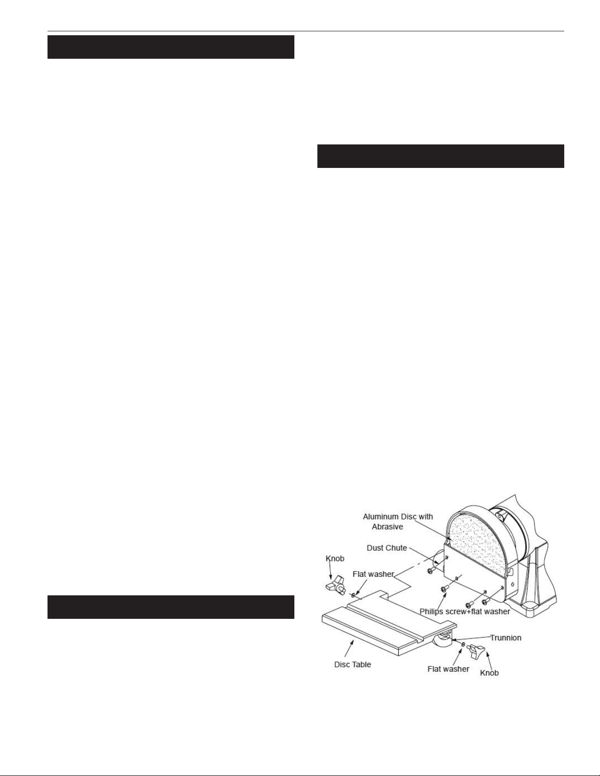
ATTACH ABRASIVE DISC TO ALUMINUM DISC
1. Remove dust chute by loosening screws and bolts.
2. Remove the adhesive cover from the back of the abrasive disc.
3. Center abrasive on aluminum disc and press to paste.
4. Make sure abrasive is pasted evenly on the aluminum disc.
5. Replace dust chute.
ASSEMBLE DISC TABLE
Refer to Figure 1.
1. Slide table onto disc guard as shown.
2. Set the disc table at right angle to the aluminum disc and se-
cure the table position using two knobs and flat washers
ADJUST DISC TABLE ANGLE
Refer to Figure 1.
1. The disc table is adjustable from 0 to 45 degree for beveled
work. To adjust disc table, loosen 2 knobs and flat washers and
adjust to desired angle
2. Use scale on disc table trunnions to set disc table from 0 to 45
degree to abrasive disc
3. When disc table is at desired angle, lock into position by tight-
ening the knobs
Figure 1 - Assemble and adjust disc table.
4
Palmgren Operating Manual & Parts List 9681061C
ASSEMBL (CONTINUED)
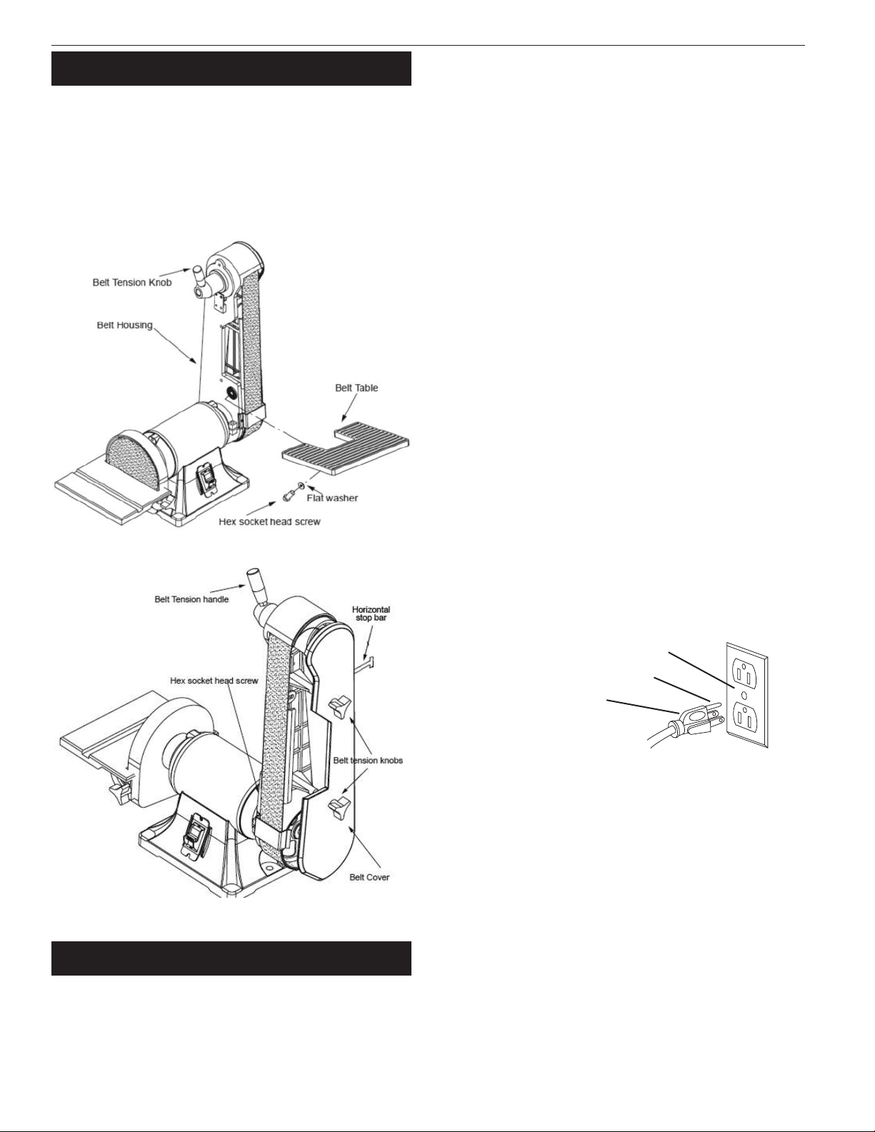
ASSEMBLE BELT TABLE
Refer to Figure 2.
1. Mount belt table to left side of belt housing using hex socket
head screw and flat washer.
2. Set the belt table at right angle to the belt
3. Be sure gap between table and belt is 1/16˝ or less. Tighten
socket head screw to secure table position.
INSTALLATION
Refer to Figures 4 and 5.
WARNING: Operation of any power tool can result in foreign ob-
jects being thrown into eyes which can result in severe eye damage.
Always wear safety goggles complying with United States
ANSI Z87.1 before commencing power tool operation.
ELECTRICAL CONNECTIONS
WARNING: All electrical connections must be performed by a
qualified electrician. Make sure tool is off and disconnected from
power source while motor is mounted, connected, reconnected or
anytime wiring is inspected.
WARNING: All electrical connections must be performed by a
qualified electrician.
WARNING: Do not connect sander to the power source until all
assembly steps have been completed.
OWER SOURCE
1. The motor is designed for operation on the voltages and fre-
quency specified.
2. Normal loads will be handled safely on voltages not more than
10% above or below the specified voltage.
3. Running the unit on voltages which are not within the range
may cause overheating and motor burnout.
4. Heavy loads require the voltage at motor terminals be not less
than the voltage specified. Power supply to the motor is con-
trolled by a single pole locking rocker switch. Remove the key to
prevent unauthorized use.
GROUNDING INSTRUCTIONS
Refer to Figures 4 and 5.
WARNING: Improper connection of equipment grounding con-
ductor can result in the risk of electrical shock. Equipment should
be grounded while in use to protect operator from electrical shock.
Check with a qualified electrician if grounding instructions are not
understood or if in doubt as to whether the tool is properly
grounded.
This equipment is for use on less than 150V, and is equipped with
an approved 3-conductor cord and a 3-prong, grounding type plug
(see Figure 4) for your protection against shock hazards.
rounding plug should be plugged directly into a properly in-
stalled and grounded 3- prong grounding-type receptacle.
Do not remove or alter grounding prong in any manner. In the
event of a malfunction or breakdown, grounding provides a path of
least resistance for electrical shock.
WARNING: Do not permit fingers to touch the terminals or plug
when installing or removing from outlet.
Plug must be plugged into matching outlet that is properly in-
stalled and grounded in accordance with all local codes and ordi-
nances. Do not modify plug provided. If it will not fit in outlet, have
proper outlet installed by a qualified electrician.
Inspect tool cords periodically, and if damaged, have repaired by an
authorized service facility.
reen (or green and yellow) conductor in cord is the grounding
wire. If repair or replacement of the electric cord or plug is neces-
sary do not connect the green (or green and yellow) wire to a live
terminal.
Where a 2-prong wall receptacle is encountered, it must be re-
placed with a properly grounded 3-prong receptacle installed in
accordance with National Electric Code and local codes and ordi-
nances.
Figure 2 - Assemble belt table.
Figure 3 - Horizontal stop bar.
Figure 4 – 3- rong receptacle
Properly grounded outlet
rounding prong
3-Prong plug

5
Palmgren Operating Manual & Parts List 9681061C
INSTALLATION (CONTINUED)
WARNING: This work should be performed by a qualified
electrician.
A temporary 3-prong to 2-prong grounding adapter (See Figure 5)
is available for connecting plugs to a two pole outlet if it is properly
grounded.
Do not use a 3-prong to 2-prong grounding adapter unless permit-
ted by local and national codes and ordinances.
(A 3-prong to 2-prong grounding adapter is not permitted in
Canada.) Where permitted, the rigid green tab or terminal on the
side of the adapter must be securely connected to a permanent
electrical ground such as a properly grounded water pipe, a prop-
erly grounded outlet box or a properly grounded wire system.
Many cover plate screws, water pipes and outlet boxes are not
properly grounded. To ensure proper ground, grounding means
must be tested by a qualified electrician.
EXTENSION CORDS
• The use of any extension cord will cause some drop in voltage
and loss of power.
• Wires of extension cord must be sufficient in size to carry and
maintain adequate voltage.
• Do not use extension cords over 25 ft. Cord must be at least 18
A.W. .
• Use only 3-wire extension cords having 3-prong grounding
type plugs and 3-pole receptacles which accept the tool plug.
• If the extension cord is worn, cut or damaged in any way, re-
place it immediately.
EXTENSION CORD LENGTH
Wire Size A.W.G.
Up to 25 ft . . . . . . . . . . . . . . . . . . . . . . . . . . . . . . . . . . . . . . . . . . . . . . . . . . 18
NOTE: Using extension cords over 25 ft. long is not recommended.
OPERATION
Refer to Figures 6 and 7.
WARNING: Operation of any power tool can result in foreign ob-
jects being thrown into eyes which can result in severe eye dam-
age. Always wear safety goggles complying with United States
ANSI Z87.1 before commencing power tool operation.
CAUTION: Always observe the following safety precautions:
• Whenever adjusting or replacing any parts on the sander turn
power off and remove the plug from power source.
• Recheck table knobs and bolts, they must be tightened securely.
• Make sure all guards are properly attached. All guards should be
securely fastened.
• Make sure all moving parts are free and clear of any interference.
• Make sure all fasteners are tight and have not vibrated loose.
• With power disconnected, test operation by hand for clearance
and adjust if necessary.
• Always wear eye protection or face shield.
• Make sure abrasive belt tracks properly. Correct tracking gives
optimum performance.
• After turning switch on, always allow belt to come up to full
speed before sanding or grinding.
• Be sure motor runs clockwise on disc side. Abrasive belt must
travel down.
• Avoid kickback by sanding in accordance with the directional
arrows.
• Keep your hands clear of abrasive belt, disc and all moving parts.
• For optimum performance do not stall motor or reduce speed.
Do not force the work into the abrasive.
• Support workpiece with belt table when sanding with belt, with
disc table when sanding with disc.
• Never push a sharp corner of workpiece rapidly against belt or
disc. Abrasive backing may tear.
• Replace abrasives when they become loaded (glazed) or frayed.
• When grinding metal, move workpiece across abrasive to pre-
vent heat build-up.
• Never attempt wet sanding. If work-piece becomes too hot to
handle, cool it in water.
BELT INSTALLATION
Refer to Figure 6.
Sanding belt should be replaced when worn, torn, or glazed.
1. Release belt tension by pulling down on tension handle. Slide
old belt off the drive and tracking wheels.
2. Pull down on the tension handle and slide new belt over the
drive and tracking wheels, center belt on wheels.
3. Replace lower guard and tighten bolt.
4. Replace belt cover and knobs.
5. Rotate belt by hand to check tracking, belt should ride centered
on drive and tracking wheels. Adjust socket head bolt at top of
tracking bracket to track belt properly. Be sure to secure socket
head bolt with hex nut.
ADJUST BELT TABLE
Refer to Figure 6.
1. To adjust belt table angle, loosen socket head bolt.
2. Tilt belt table to desired position and secure by tightening
socket head bolt.
Figure 5 – 2- rong receptacle with adapter
rounding lug
Adapter
3-Prong plug 2-Prong re-
ceptacle
Make sure this is con-
nected to a known
grounded receptacle
Figure 6 – Operation
Tracking Bracket Knob
Disc Table
Belt Table
Lower
uard
Work Stop
Release Belt Cover
Belt Platen Screws
Knob Belt Housing Bolt

6
Palmgren Operating Manual & Parts List 9681061C
OPERATION (CONTINUED)
ADJUST BELT ASSEMBLY OSITION
Refer to Figure 6, page 5.
The sanding belt assembly can be adjusted from vertical to hori-
zontal position.
1. Loosen the belt housing bolt that clamps belt housing to motor
assembly.
2. Tilt belt assembly to desired position (from vertical to horizontal).
Secure belt assembly position by tightening belt housing bolt.
WORK STO
Refer to Figure 6, page 5.
The work stop can be used instead of the belt table.
1. Remove socket head bolt and washers holding belt table on
sander. Remove belt table.
2. Mount work stop to sander using the socket head bolt and
washer.
NOTE: Position work stop properly so gap between work stop and
belt is 1/16˝ or less. Tighten socket head bolt and washers.
CONTOUR SANDING
Refer to Figure 6,, page 5.
1. Belt platen can be removed for contour sanding. Remove belt
cover knobs and belt cover.
2. Remove socket head bolts and washers holding platen to belt
housing. Remove belt platen.
3. Replace belt cover and belt cover knobs. When contour sanding
is complete, replace belt platen. Position belt platen as close to
belt as possible so that platen does not contact belt.
ABRASIVE BELT FINISHING
Refer to Figure 7, page 8.
1. Finishing flat surfaces: Hold workpiece firmly with both hands,
keep fingers away from abrasive belt.
Use work stop. Work stop is used to position and stabilize work.
Keep end butted against workstop and move work evenly across
abrasive belt. Use extra caution when finishing very thin pieces.
For finishing long pieces: remove work stop. Apply only enough
pressure to allow abrasive belt to remove material.
2. Finishing curved edges: Finish outside curves on flat portion of
abrasive belt. Finish inside curves on drive wheel portion of
abrasive belt.
3. Finishing end grain: It is more convenient to finish ends of long
workpieces with abrasive belt in a vertical position.
RE LACING ABRASIVE DISC
Refer to Figure 7, page 8.
1. Loosen and remove knobs (Ref. No. 28).
2. ently press down on disc table and slide out disc table.
3. Remove old abrasive disc by peeling it from aluminum disc. Re-
moving aluminum disc from motor shaft is not necessary.
4. Clean aluminum disc if necessary. Select proper abrasive disc
and apply to aluminum disc.
5. Replace disc table.
ABRASIVE DISC FINISHING
1. Abrasive disc sanding is well suited for finishing small end sur-
faces and convex edges.
2. Move workpiece across down side (right) of face of
abrasive disc.
3. Abrasive disc moves fastest and removes more material at outer
edge.
4. For accuracy, use the miter gauge.
USING MITER GAUGE
Refer to Figure 7, page 8.
1. The miter gauge is used on disc table. Use the miter gauge for
securing the work and holding the proper angle while sanding.
2. Adjust the angle by repositioning the protractor scale and lock-
ing it into place with knob.
3. Check accuracy of miter gauge scale.
4. Use a combination square to adjust miter gauge square to face
of disc. Loosen screw and reposition indicator if necessary.
MAINTENANCE
WARNING: Make certain that the unit is disconnected from power
source before attempting to service or remove any component.
CLEANING
1. Keep machine and workshop clean. Do not allow sawdust to ac-
cumulate on the belt and disc sander.
2. Keep the wheels clean. Dirt on wheels will cause poor tracking
and belt slippage.
3. Operate sander with dust collector to keep dust from accumu-
lating.
WARNING: After sanding wood or non-metallic material, always
clean dust collector and guards of sawdust before grinding metal.
Sparks could ignite debris and cause a fire.
4. Be certain motor is kept clean and is frequently vacuumed free
of dust.
5. Use soap and water to clean painted parts, rubber parts and
plastic guards.
LUBRICATION
1. The shielded ball bearings in this sander are permanently lubri-
cated at the factory. They require no further lubrication.
2. When operation seems stiff, a light coat of automobile-type wax
applied to the belt table and disc table will make it easier to
feed the work while finishing.
3. Do not apply wax to the belt platen. Belt could pick up wax and
deposit it on wheels causing belt to slip.
KEE SANDER IN RE AIR
1. If power cord is worn, cut or damaged, have it replaced
immediately.
2. Replace worn abrasives when needed.
3. Replace any damaged or missing parts. Use parts list to
order parts.

TROUBLESHOOTING
SYM TOM OSSIBLE CAUSE(S) CORRECTIVE ACTION
Motor will not start
Motor will not start; fuses blown or
circuit breakers tripped
Motor fails to develop full power
(power output of motor decreases
rapidly with decrease in voltage at
motor terminals)
Motor overheats
Motor stalls
(resulting in blown fuses or
tripped circuit breakers)
Machine slows down
while operating
Abrasive belt runs off top wheel
1. Blown line fuse or tripped circuit breaker
2. Low line voltage
3. Defective switch
4. Defective, blown capacitor
1. Overloading due to binding
2. Defective plug
3. Defective cord
4. Defective switch
5. Motor wired for different
line voltage
6. Faulty internal wiring
1. Power line overloaded with lights, appli-
ances and other motors
2. Undersized wires or circuits too long
3. eneral overloading of power company’s
facilities
Motor overloaded
1. Short circuit in motor or loose connections
2. Low voltage
3. Motor wired for different line voltage
4. Incorrect fuses or circuit breakers in power
line
5. Motor overloaded
Applying too much pressure to
workpiece
Not tracking properly
1. If fuse is blown, replace with fuse of proper size. If
breaker tripped, reset it
2. Check power supply for voltage and correct as
needed
3. Replace switch
4. Replace capacitor
1. Clean around wheels and shaft and/or replace
bearings
2. Replace plug
3. Replace cord
4. Replace switch
5. Rewire motors as per line voltage
(See “Electrical Connections”, page 4)
6. Contact authorized Dayton Service Center
1. Reduce load on power line
2. Increase wire sizes, or reduce length of wiring
3. Request a voltage check from power company
Reduce load on motor
1. Inspect connections in motor for loose or shorted
terminals or worn insulation on lead wires
2. Correct the low line voltage conditions
3. Rewire motor as per line voltage
4. Install correct fuses or circuit breakers
(See “Electrical Connections”, page 4)
5. Reduce load on motor
Ease up on pressure
See “Belt Installation”, page 5
7
Palmgren Operating Manual & Parts List 9681061C
8
Palmgren Operating Manual & Parts List 9681061C
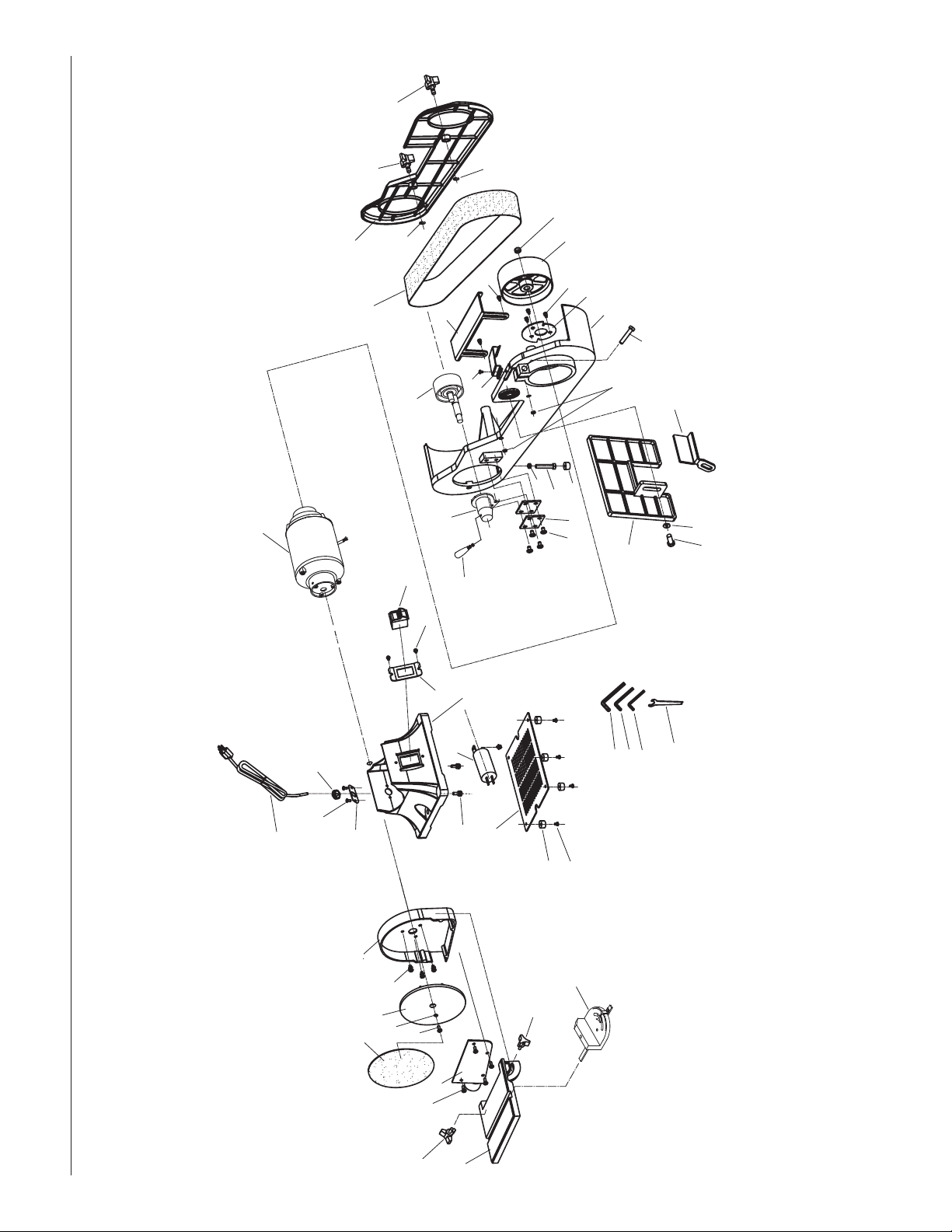
Figure 7 - arts illustration for 2 x 6˝ Belt and Disc Sander.
32
11
10
9
8
7
6
45
2
3
1
2
23
25
24
21
22 20
14
13
12
15
53
52
51
50
19
14
17
16
35
36
37
34
33
26
27
43
41 42
3818
28
54
44
49 45
46
10 47 48
39
40
29
31
30
32
30

9
Palmgren Operating Manual & Parts List 9681061C
1 Miter gauge assembly 9642315.01 1
2 Disc table knob 9642316.01 2
3 Disc table 9642317.01 1
4 Philips screw and flat washer 4 x 6mm * 4
5 Dust chute 9642318.01 1
6 Disc paper 6˝ PSA 9603126.00 1
7 Hex screw 9642319.01 1
8 Outer toothed washer 6mm dia. * 1
9 Disc 9642320.01 1
10 Philips screw and spring washer 5 x 10mm * 6
11 Disc guard 9642321.01 1
12 Power cord 9642322.01 1
13 Cord fixing plate 9642323.01 1
14 Philips screw 5 x 8mm * 4
15 Cord clip 9642324.01 1
16 Motor assembly 9642325.01 1
17 Locking switch 9642326.01 1
18 Philips screw 4 x 8mm * 1
19 Switch plate 9642327.01 1
20 Base N/A 1
21 Capacitor 9642328.01 1
22 Philips screw and spring washer 6 x 20mm * 2
23 Base plate 9642329.01 1
24 Rubber foot 9642330.01 4
25 Philips screw and flat washer 4 x 12mm * 4
26 Tension handle 9642331.01 1
27 Tension handle assembly 9642332.01 1
28 Eccentric shaft assembly 9642333.01 1
29 Belt, abrasive 2 x 42˝ 80x 9608901.00 1
30 Retaining ring 9642334.01 2
31 Belt cover 9642335.01 1
32 Belt tension knob 9642336.01 2
33 Philips screw, spring washer and flat washer 5 x 10mm * 4
34 Spring plate 9642337.01 4
35 Support 9642338.01 1
36 Hex bolt 8 x 90mm * 1
37 Hex nut 8mm * 1
38 Belt cover support 9642339.01 1
39 Hex screw and toothed washer 6 x 16mm * 2
40 Belt platen 9642340.01 1
41 Hex screw 10 x 16 * 1
42 Flat washer 10mm dia. * 1
43 Belt table 9642341.01 1
44 Hex screw 8 x 25mm * 1
45 Belt housing 9642342.01 1
46 Stop bracket 9642343.01 1
47 Drive wheel 9642344.01 1
48 Hex nut 12mm * 1
49 Hex nut 6mm * 2
50 Hex wrench 5mm * 1
51 Hex wrench 6mm * 1
52 Hex wrench 8mm * 1
53 Wrench * 1
54 Work stop 9642345.01 1
∆ Operating Instructions & Parts Manual 9631694.01
REPLACEMENT PARTS LIST FOR 2 X 6" BELT AND DISC SANDER
∆ Not Shown.
* Standard hardware item available locally.
Ref.
No. Description art No. Qty.
Ref.
No. Description art No. Qty.

NOTES
10
Palmgren Operating Manual & Parts List 9681061C

NOTES
11
Palmgren Operating Manual & Parts List 9681061C

WARRANT
Palmgren warrants their products to be free of defects in material or workmanship. This warranty does not cover defects due directly or
indirectly to misuse, abuse, normal wear and tear, failure to properly maintain the product, heated, ground or otherwise altered, or used for a
purpose other than that for which it was intended. The warranty does not cover expendable and/or wear parts (i.e. v-belts, coated screws,
abrasives), damage to tools arising from alteration, abuse or use other than their intended purpose, packing and freight. The duration of this
warranty is expressly limited to one year parts and labor, unless otherwise noted below beginning from the date of delivery to the original
user. The Palmgren products carry the following warranties on parts with a 1 year warranty on labor:
• USA Machine vises – Lifetime
• IQ Machine vises – Lifetime
• Bench vises – Lifetime
• Positioning tables – Lifetime
• Bench grinders & buffers – 3 years
• Tapping machines – 3 years
• Drilling machines – 3 years
• Finishing machines – 3 years
• Band saws – 3 years
• Work stands – Lifetime
• Arbor presses – Lifetime
• Metal forming equipment – 3 years
• Accessories – 1 year
The obligation of Palmgren is limited solely to the repair or replacement, at our option, at its factory or authorized repair agent of any part
that should prove deficient. Purchaser must lubricate and maintain the product under normal operating conditions at all times. Prior to
operation become familiar with product and the included materials, i.e. warnings, cautions and manuals. Failure to follow these
instructions will void the warranty.
This warranty is the purchaser’s exclusive remedy against Palmgren for any deficiency in its products. Under no circumstances is Palmgren
liable for any direct, indirect, incidental, special or consequential damages including lost profits in any way related to the use or inability to
use our products. This warranty gives you specific legal rights which may vary from state to state.
SERVICE & RE AIR
1. If a Palmgren product requires a repair or warranty service DO NOT return the product to the place of purchase.
2. All warranty related work must be evaluated and approved by Palmgren.
3. Prior to returning any item the user must obtain factory approval and a valid R A number.
4. For instructions and R A number call toll free (800) 827-3398.
Palmgren Operating Manual & Parts List 9681061C
11 2017
Table of contents
Other CH Hanson Sander manuals


Popular Sander manuals by other brands


Amano
Amano American Sanders 3DS Operator's manual

Makita
Makita PV301DZJ instruction manual

Black & Decker
Black & Decker KA110 instruction manual

Makita
Makita 9031 instruction manual

Alpha Professional Tools
Alpha Professional Tools VSP-320 instruction manual

Chicago Pneumatic
Chicago Pneumatic CP35 Series Operator's manual