CH Hanson NORSE 9681310 User manual

Operating Manual & Parts List
9681310 & 9681311
DISC SANDER
with Stand
Read carefully and follow all safety
rules and operating instructions before
first use of this product.
9644211.01-0519

Model #: ___________________
Serial #: ____________________
Purch. Date: ________________
3
NO SE Operating Manual & Parts List 9681310 & 9681311
GETTING STARTED
Save this manual
You will need this manual for the safety warnings and
precautions, assembly instructions, operating and maintenance
procedures, parts list and diagram. Keep your invoice with this
manual. Write the invoice number on the inside of the front cover.
Keep this manual and invoice in a safe and dry place for future
reference.
Structural requirements
Make sure all supporting structures and load attaching
devices are strong enough to hold your intended loads.
If in doubt, consult a qualified structural engineer.
Electrical requirements
The power supply to your specific Disc Sander is
determined by its model number. Model 9681310
requires 115V, 60Hz, 17.8 amps. Model 9681311
requires 230V, 60Hz, 11.2 amps single phase. The
standard allowable voltage variation is a plus or minus 10%.
UNPACKING
When unpacking, check to make sure all parts listed below are
included. If any parts are missing or broken, please contact your
local retailer.
Never use highly volatile solvents. Avoid
getting cleaning solution on paint as it
may tend to deteriorate these finishes. Use soap and water
on painted components.
IMPORTANT: Many unpainted steel surfaces will have been
coated with a protectant. To ensure proper fit and operation,
remove the coating. Coating can be easily removed with mild
solvents, such as mineral spirits and a soft cloth. Avoid getting
solution on paint or any of the rubber/plastic parts. Solvents may
deteriorate these finishes. Use soap and water on paint, plastic
or rubber components. After cleaning, cover all exposed surfaces
with a light coating of oil.
Contents:
• Disc Sander
• 5mm Hex Wrench
• Miter Guage
• Adhesive Backed Sanding Disc
• Anti-vibration Foot Pads
Unpack
Remove all the over packing materials, but leave unit
attached to its pallet. Do not discard packing materials
until after the machine has been inspected for damage and
completeness. Locate loose parts and set them aside.
Inspect
• After unpacking the unit, carefully inspect for any
damage that may have occurred during transit.
Check for loose, missing or damaged parts.
Shipping damage claims must be filed with the
carrier.
• All tools should be visually inspected before use, in addition
to regular periodic maintenance inspections.
• Be sure that the voltage labeled on the unit matches your
power supply.
SAFETY RULES
For your own safety, read all of the
instructions and precautions before
operating tool.
Always follow proper operating
procedures as defined in this manual even
if you are familiar with the use of this tool or similar
machines. Remember that being careless for even a fraction
of a second can result in severe personal injury.
PROPOSITION 65 WARNING: Some dust created by
using power tools contain chemicals known to the state
of California to cause cancer, birth defects or other
reproductive harm.
Some examples of these chemicals are:
• Lead from lead-based paints.
• Crystalline silica from bricks and cement and other masonry
products
• Arsenic and chromium from chemically-treated lumber.
Your risk from these exposures varies, depending on how often
you do this type of work. To reduce your exposure to these
chemicals: work in a well ventilated area and work with approved
safety equipment. Always wear a OSHA/NIOSH approved,
properly fitting face mask or respirator when using such tools.
Preparing for your job
• Wear safety glasses complying with United States ANSI
Z87.1. Everyday glasses only have impact resistant lenses.
They are not safety glasses.
• Wear an ANSI approved dust mask.
• Wear proper apparel when using this tool. Do not wear loose
clothing, gloves, neckties, rings, bracelets or other jewelry
which may get caught up in moving parts of this machine.
• When using this machine, wear protective hair covering to
contain long hair.
• Wear safety shoes with non-slip soles.
• Bealert and think clearly. Never operate power tools when
tired, intoxicated or when taking medications that cause
drowsiness.
Preparing the work area for your job
• Keep your work area clean. Cluttered work areas invite
accidents.
• Do not set up or use the Disc Sander in dangerous
environments. Do not set up or use the Disc Sander in damp
or wet locations. Do not expose this machine to rain.
• Make sure your work area is properly lighted.
• Proper electrical connections should be set up for this
machine.
• Extension cords should have a grounding prong and the

4
NO SE Operating Manual & Parts List 9681310 & 9681311
4
three wires of the extension cord should be of the proper
gauge.
•Keep visitors at a safe distance from work area.
•Keep children out of the workplace. Make your workshop
childproof. Use padlocks, master switches or remove switch
keys to prevent any unintentional use of your power tools.
Maintaining your tool
•Always unplug the tool and remove it from its power source
prior to inspection. If your machine plugs into an electrical
outlet do not unplug the tool by pulling on the cord.
• Consult this manual for specific maintenance and adjustment
procedures.
•Keep the tool clean for safest operation. Metal or wood dust
build ups can become combustible.
• Check for damaged parts. A part that is damaged should
be properly repaired or replaced. Do not perform makeshift
repairs. Use the parts list in this manual to order repair parts.
Repairs must be made by a qualified technician.
Know how to use your tool
Dusty work environments may be
hazardous to your health. Always wear a
OSHA/NIOSH approved, properly fitting face mask or
respirator.
The operation of any machine can result
in foreign objects being thrown into the
eyes, which can result in severe eye damage. Always wear
safety goggles complying with United States ANSI Z87.1.
(shown on package) before commencing power tool
operation.
Think safety! Safety is a combination of
operator common sense and alertness at
all times when tool is being used.
•Know your tool. Learn the tool’s operation, application and
specific limitations.
•Keep your hands away from moving parts and sanding
surfaces.
•Never operate the machine without the disc guards in place.
• Completely disconnect this machine from its power source
when changing an abrasive disc.
• Use the right tool for the job. Do not force a tool or
attachment to do a job for which it was not designed.
•Toreduce the risk of electrical shock, never use the machine
in rain or allow it to become wet.
• Never attach the Disc Sander to a dust extraction unit used
for wood sanding if you are sanding metal. The sparks can
cause a fire or explosion.
•Turn the tool off immediately in the case of an emergency.
Completely remove the tool from its power source before
attempting to fix the issue.
• Never leave tool running unattended. Turn the power off and
do not leave tool until it comes to a complete stop.
• Do not use the tool as a toy or let children play with it. Care
should be taken when using the tool around children or
animals.
•Avoid accidental start-ups. Make sure that the power switch
is in the OFF position before plugging the machine in or
connecting it into an appropriate electrical resource.
• Do not overreach. Keep proper footing and balance.
• Never stand on the machine. Serious injury could occur if the
tool tips or if the sanding disc is unintentionally contacted.
•Only use recommended accessories. The improper use of
accessories may create a risk of operator injury.
• Handle workpieces correctly to help protect your hands from
possible injury.
•Support your workpiece with the supplied miter gauge or the
work table. Never “free-hand” sand a workpiece.
• Maintain a 1/16” maximum clearance or less between table
and sanding disc.
•Follow OSHA lock-out, tag-out procedures to prevent
accidental machine starts.
SPECIFICATIONS
Disc Sanding Machines
Model 9681310
Disc Sander
Model 9681311
Disc Sander
Electrical requirements
phase
230V, 60 Hz, single
phase
Amps AC 17.8A 11.2A
Motor Size 1.5 HP 2 HP
Disc speed (RPM) 1750 1750
Sanding disc diameter 16" 20"
Table size (L x W) 18.58" x 8.5” 22.68" x 8.5”
Table tilt-In angle 5˚ 5˚
Table tilt-out angle 45˚ 45˚
Dust collection port
diameter 4" 4"
Overall Dimensions
(L x W x H) 27.84" x 23.33" X 44.44"
Gross pkg. weight 266.76 lbs. 313.5 lbs.
115V, 60 Hz, single
27.75" x 27.68" x 46.44"

5
NO SE Operating Manual & Parts List 9681310 & 9681311
5
Electrical connections
Make sure the tool is off before plugging it
into a power source to prevent accidental
starts.
Do not permit fingers to touch the
terminals of plug when installing or
removing from outlet.
Electrical safety
• Double insulated tools are equipped with a polarizing three
pronged plug (one blade is wider than the other.) This plug
will fit in a polarized outlet only one way. If the plug does not
fit fully into the outlet, reverse the plug. If it still does not fit,
contact a qualified electrician to install a polarized outlet. Do
not change the plug in any way.
• Double insulation eliminates the need for the three wire
grounded power cord and grounded power supply system.
Before plugging in the tool, be certain the outlet voltage
supplied is within the voltage marked on the nameplate.
• Avoid body contact with grounded surfaces such as pipes,
radiators, ranges and refrigerators. There is an increased
risk of electric shock if your body is grounded. If operating
the power tool in damp locations is unavoidable, a Ground
Fault Circuit Interrupter must be used to supply the power to
your tool. Rubber soled footwear will further enhance your
personal safety.
4. Don’t expose this or any tools to rain or wet conditions. Water
entering a power tool will increase the risk of electric shock.
5. Do not abuse the cord. Never pull on a cord to unplug it from
an outlet. Keep the cord away from heat, oil, sharp edges
or moving parts. Replace damaged cords immediately.
Damaged cords increase the risk of electric shock.
Extension cords
• The use of an extension cord will cause some drop in voltage
and loss of power.
• Wires of the extension cord must be of sufficient size to carry
the current and maintain adequate voltage.
• Use the table to determine the minimum wire size (A.W.G)
extension cord.
• Use only 3-wire extension cords having 3-prong grounding
type plugs and 3-pole receptacles which accept the tool plug.
• If the extension cord is worn, cut or damaged in any way,
replace it immediately.
Extension cord length
Wire Size A.W.G.
Up to 25 ft 16
25 to 100 ft 14
NOTE: Using extension cords over 100 ft long is not
recommended.
ASSEMBLY/INSTALLATION
This tool must be connected to or plugged
into a properly grounded outlet. Never
operate the machine if it is not properly grounded to help
prevent electrical shock.
Power source
• The motor on this machine is designed for operation on
the voltage and frequency specified. Normal loads will be
handled safely on voltages not more than 10% above or
below specified voltage.
• Running the unit on voltages which are not within the range
may cause overheating and motor burn-out. Heavy loads
require that the voltage at the motor terminals be no less
than the voltage specified.
Lifting and setting up the machine
1. Remove any crating or outer packing materials covering the
machine. Leave the machine attached to its pallet.
NOTE: Disc sanding machines are heavy. Be certain any hoists
or devices used to lift this machine are capable of
handling the weight. The machine may tip as it is lifted.
You can minimize this tipping by rigging an additional
slings over the machine as needed. Be careful
when using a sling to prevent it from damaging any
components on the machine. Carefully steady the
machine to prevent it from spinning, but do not stand
under the machine.
2. Remove all accessory items from the pallet or machine table.
Compare these items with those listed on page 3.
3. The machine must be placed on a solid concrete floor away
from any vibrations transmitted from adjacent machines.
Unless substantially constructed, and braced a wood floor
should be avoided.
4. Check all lock handles on the machine to ensure they are
tight.
5. Remove any nuts, bolts or fasteners securing the machine to
the pallet.
6. Center an overhead crane or other suitable lifting device and
sling arrangement over the machine.
7. Carefully lift the machine off the pallet. Raise the machine no
higher than necessary to clear the hold-down hardware and
pull the pallet out of the way. DO NOT place your hands or
feet underneath the machine when removing the pallet.
8. Place the machine into a final position on a flat surface
allowing adequate space around the machine for workpieces
and dust extraction connection. (see diagrams on pg. 6)
9. When the machine is being lowered into its final location,
level it using the supplied anti-vibration feet.
10. Use a highly accurate spirit or laser level for leveling the
machine. Leveling should be done on the top of the stand
since this is the reference standard for both side-to-side and
front-to-back leveling. It is important that the machine be
properly leveled and for optimum performance.

6
NO SE Operating Manual & Parts List 9681310 & 9681311
ASSEMBLY/INSTALLATION (CONTINUED)
Lifting and setting up the machine
Shown below are the dimensions for the disc sanding machines.
You can use the information below to place your machine into its
final position. Also, allow extra space around the machine for the
handing larger workpieces and dust extraction connections.
Front
L
H
Side
W
Length Width Height
Model 9681314 27.84” 23.33” 44.44”
Model 9681315 27.75” 27.68” 46.44”
Attaching the sander to a dust extraction unit
Never connect a disc sander being used
for metal sanding to a wood dust
extraction system. The sparks created from sanding metal
can cause the wood sawdust to catch fire or explode.
• Your disc sander machine can be attached to a dust
extraction system to keep your work shop cleaner.
Use of a dust extraction unit strongly recommended.
• This machine uses a 4” diameter dust port. Locate the dust
port on the left side of the machine. Slide a suitable hose
over the port and secure it with a hose clamp. Dryer vent
hosing material is not acceptable.
OPERATION
Dusty work environments may be
hazardous to your health. Always wear a
OSHA/NIOSH approved, properly fitting face mask or
respirator.
Always wear safety glasses complying
with U.S. ANSI Z87.1 before beginning any
sanding operation.
Make sure all disc guards are in securely
in place before starting the disc sanding
machine. Never operate the machine without the guards.
Completely disconnect the disc sanding
machine before making any adjustments
or changing abrasive sanding discs.
Installing an abrasive sanding disc
NOTE: While not required, it is much easier to make table
alignment adjustments while the abrasive sanding disc is
removed (see pg. 7).
A
1. Remove the two knobs (A) holding the upper disc guard in
place.
B
3. Loosen and remove the four hex bolts (B) under the
workpiece table using the supplied 5 mm hex wrench.
Remove the workpiece table.
7
NO SE Operating Manual & Parts List 9681310 & 9681311
Table parallel alignment to disc
Table parallel alignment to disc
p
Table parallel alignment to disc
g
lel alignment to disc
v
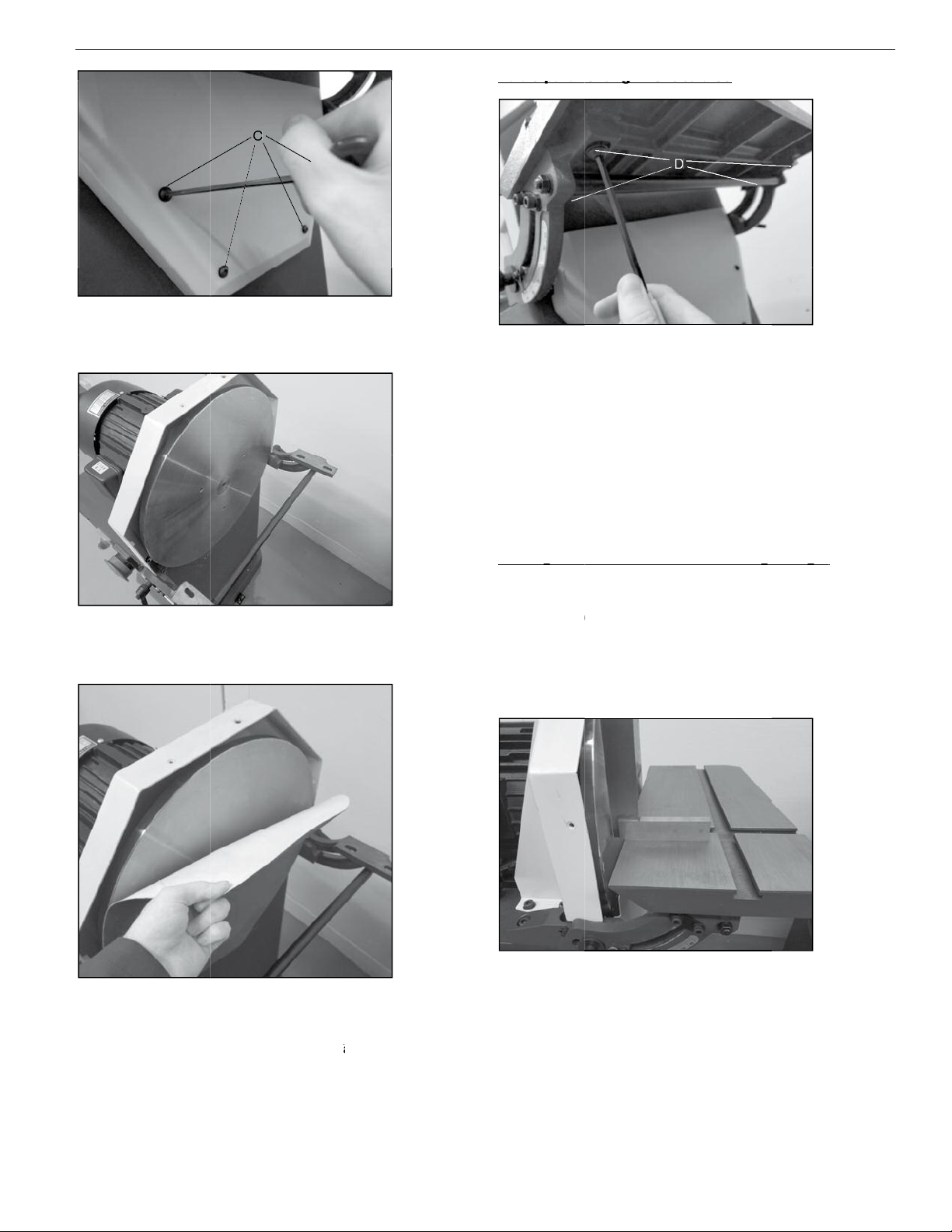
Remove the lower guard.
remove the four hex bolts (C) holding on the lower guard.
Use the supplied 4 mm hex wrench attached to the base to3.
Remove the lower guard.
remove the four hex bolts (C) holding on the lower guard.
Use the supplied 4 mm hex wrench attached to the base to
remove the four hex bolts (C) holding on the lower guard.
Use the supplied 4 mm hex wrench attached to the base to
table can move.
Loosen the four bolts under the miter brackets enough so the1.
o set the table gap perform the following steps:
T
To set the table gap perform the following steps:
touch the sanding disc and has a clearance gap of 1/16” or less.
disc to ensure flush sanding.
The workpiece table must be properly aligned to the sanding
table can move.
Loosen the four bolts under the miter brackets enough so the
o set the table gap perform the following steps:
touch the sanding disc and has a clearance gap of 1/16” or less.
The table must be set to it does notdisc to ensure flush sanding.
The workpiece table must be properly aligned to the sanding
Loosen the four bolts under the miter brackets enough so the
o set the table gap perform the following steps:
touch the sanding disc and has a clearance gap of 1/16” or less.
The table must be set to it does not
The workpiece table must be properly aligned to the sanding
Remove the sanding disc from the flywheel disc.3.
Remove the sanding disc from the flywheel disc.
g
following steps:
o set a true 90º reference for your disc sander perform the
T
To set a true 90º reference for your disc sander perform the
performs accurate flush and angled miter sanding operations.
The workpiece table can be adjusted to ensure your disc sander
Setting the
during the process.
ighten the four bolts making sure the table does not moveT3.
consistently 1/16” or less from front to back.
Align the table so the gap between the disc and table is2.
g
following steps:
o set a true 90º reference for your disc sander perform the
performs accurate flush and angled miter sanding operations.
The workpiece table can be adjusted to ensure your disc sander
miter bracket to a 90º right angle
during the process.
ighten the four bolts making sure the table does not move
consistently 1/16” or less from front to back.
Align the table so the gap between the disc and table is
g
o set a true 90º reference for your disc sander perform the
performs accurate flush and angled miter sanding operations.
The workpiece table can be adjusted to ensure your disc sander
ht angle
ighten the four bolts making sure the table does not move
consistently 1/16” or less from front to back.
Align the table so the gap between the disc and table is
grease.
Clean the flywheel disc of any left-over adhesive, dirt or4.
Clean the flywheel disc of any left-over adhesive, dirt or
Clean the flywheel disc of any left-over adhesive, dirt or
removed.
alignment adjustments while the abrasive sanding disc is
While not required, it is much easier to make tableNOTE:
following steps:
alignment adjustments while the abrasive sanding disc is
While not required, it is much easier to make table
alignment adjustments while the abrasive sanding disc is
While not required, it is much easier to make table
Aligning the bottom of the disc and adheresanding disc.
Remove the adhesive backing from the top half of the5.
Aligning the bottom of the disc and adhere
Remove the adhesive backing from the top half of the
Aligning the bottom of the disc and adhere
Remove the adhesive backing from the top half of the
Use a machinist square or suitable tool and adjust the table2.
the workpiece table so it can move.
Slightly loosen the miter adjustment levers on both ends of1.
Use a machinist square or suitable tool and adjust the table
the workpiece table so it can move.
Slightly loosen the miter adjustment levers on both ends of
Use a machinist square or suitable tool and adjust the table
Slightly loosen the miter adjustment levers on both ends of
Replace the lower guard, table and upper guard.7.
ensure it is tightly adhered to the flywheel disc.
After the new abrasive disc is attached, press firmly on it to6
the abrasive sanding disc on the flywheel disc.
adhere the bottom of the sanding disc.
Then remove the bottom adhesive backing andthe top first.
Aligning the bottom of the disc and adheresanding disc.
Replace the lower guard, table and upper guard.
ensure it is tightly adhered to the flywheel disc.
After the new abrasive disc is attached, press firmly on it to
the abrasive sanding disc on the flywheel disc.
ake care
T
Take care to center
adhere the bottom of the sanding disc.
Then remove the bottom adhesive backing and
Aligning the bottom of the disc and adhere
After the new abrasive disc is attached, press firmly on it to
ake care to center
Then remove the bottom adhesive backing and
Aligning the bottom of the disc and adhere
Adjust the indicator pointer to 90º if required.4.
Carefully tighten the adjustment lever and recheck the table.3.
until the square rests flush on both the table and disc.
Use a machinist square or suitable tool and adjust the table2.
Adjust the indicator pointer to 90º if required.
Carefully tighten the adjustment lever and recheck the table.
until the square rests flush on both the table and disc.
Use a machinist square or suitable tool and adjust the table
7
Adjust the indicator pointer to 90º if required.
Carefully tighten the adjustment lever and recheck the table.
until the square rests flush on both the table and disc.
Use a machinist square or suitable tool and adjust the table

8
NO SE Operating Manual & Parts List 9681310 & 9681311
urn the pointer from the middle OFF position to the leftT3.
urn the pointer from the middle OFF position to the left
urn the pointer from the middle OFF position to the left
Setting the miter tool to a 90º right angle
Setting the miter tool to a 90º right angle
g
It is recommended that you sand your workpiece with the disc
Setting the
hand or knee.
position, or push the emergency stop button with either your
o stop the machine, turn the pointer back the middle OFF
T
To stop the machine, turn the pointer back the middle OFF
5.
direction.
The right REV position will rotate the disc in the clockwise4.
motion.
FOR position, and the disc will spin in the counter-clockwise
g
It is recommended that you sand your workpiece with the disc
e guards for forward or reverse rotation
hand or knee.
position, or push the emergency stop button with either your
o stop the machine, turn the pointer back the middle OFF
direction.
The right REV position will rotate the disc in the clockwise
FOR position, and the disc will spin in the counter-clockwise
urn the pointer from the middle OFF position to the left
It is recommended that you sand your workpiece with the disc
verse rotation
position, or push the emergency stop button with either your
o stop the machine, turn the pointer back the middle OFF
The right REV position will rotate the disc in the clockwise
FOR position, and the disc will spin in the counter-clockwise
g
Use a machinist square or suitable tool and adjust the face2.
Slightly loosen the miter tool adjustment push knob (E).1.
tool while the abrasive sanding disc is removed.
While not required, it is much easier to adjust the miterNOTE:
steps:
o set a true 90º refe
T
To set a true 90º reference for miter tool, perform the following
performs accurate flush and angled miter sanding operations.
The miter tool can be adjusted to ensure your disc sander
Setting the miter
g g
Use a machinist square or suitable tool and adjust the face
Slightly loosen the miter tool adjustment push knob (E).
tool while the abrasive sanding disc is removed.
While not required, it is much easier to adjust the miter
o set a true 90º reference for miter tool, perform the following
performs accurate flush and angled miter sanding operations.
The miter tool can be adjusted to ensure your disc sander
r tool to a 90º right angle
Use a machinist square or suitable tool and adjust the face
Slightly loosen the miter tool adjustment push knob (E).
While not required, it is much easier to adjust the miter
o set a true 90º reference for miter tool, perform the following
performs accurate flush and angled miter sanding operations.
The miter tool can be adjusted to ensure your disc sander
according to the rotation of the sanding disc.
depending on the guard’
and removing the two black knobs on the top and back (or front
rear half of the sanding disc. Move the top guard by loosening
The top disc guard can be moved to expose either the front or
rotating down toward the workpiece to hold it against the table.
It is recommended that you sand your workpiece with the disc
o set up the machine for
T
To set up the machine for
rotation set up
Counterclockwise
according to the rotation of the sanding disc.
The guard’s set up).depending on the guard’
and removing the two black knobs on the top and back (or front
rear half of the sanding disc. Move the top guard by loosening
The top disc guard can be moved to expose either the front or
rotating down toward the workpiece to hold it against the table.
It is recommended that you sand your workpiece with the disc
o set up the machine for
rotation set up
Counterclockwise
Front
Machine
s position is setThe guard’
and removing the two black knobs on the top and back (or front
rear half of the sanding disc. Move the top guard by loosening
The top disc guard can be moved to expose either the front or
rotating down toward the workpiece to hold it against the table.
It is recommended that you sand your workpiece with the disc
g
out.
, and the emergency stop button is pulledelectrical supply
Ensure the machine is properly connected to a suitable1.
Turning on the sa
Adjust the indicator pointer (F) to 90º if required.4.
miter tool to ensure it is square.
Carefully tighten the adjustment push knob and recheck the3.
tool face and flywheel disc.
of the miter tool until the square rests flush on both the miter
g
, and the emergency stop button is pulled
Ensure the machine is properly connected to a suitable
anding disc machine
Adjust the indicator pointer (F) to 90º if required.
miter tool to ensure it is square.
Carefully tighten the adjustment push knob and recheck the
tool face and flywheel disc.
of the miter tool until the square rests flush on both the miter
, and the emergency stop button is pulled
Ensure the machine is properly connected to a suitable
Adjust the indicator pointer (F) to 90º if required.
Carefully tighten the adjustment push knob and recheck the
of the miter tool until the square rests flush on both the miter
portion of the disc.
set the disc guard to the back
counterclockwise rotation,
o set up the machine for
T
To set up the machine for
the back portion of the disc.
guard to the front and sand on
clockwise rotation set the disc
o set up the machine for
T
To set up the machine for
Clockwise rotation set up
portion of the disc.
set the disc guard to the back
counterclockwise rotation,
o set up the machine for
Front
Machine
the back portion of the disc.
guard to the front and sand on
clockwise rotation set the disc
o set up the machine for
Clockwise rotation set up
emergency stop button.
Locate the power and direction switch to the left of the2.
TROUBLESHOOTING GUIDE
Symptom
Sanding paper becomes glazed.
emergency stop button.
Locate the power and direction switch to the left of the
TROUBLESHOOTING GUIDE
Possible Cause(s)
Sanding paper becomes glazed. Sanding a painted or coated surface.
Locate the power and direction switch to the left of the
Corrective Action
grit.
Use open-end grain/flint sanding paper with a coarserSanding a painted or coated surface.
Possible Cause(s)
Corrective Action
Use open-end grain/flint sanding paper with a coarser
Use open-end grain/flint sanding paper with a coarser
orkpiece pulled fro
W
Workpiece pulled from hand.
.quickly
Sanding paper burns, or clogs
Burn marks on workpiece.
orkpiece pulled from hand.
Allow the disc to cut freely
hand sand workpieces.
No support for workpiece. Do not free
disc.
Sanding paper burns, or clogs
disc.
Do not force the workpiece into sanding
rong sanding paper surface.Burn marks on workpiece.
Forcing the workpiece into the sanding
ood is wet or g
W
W
Wood is wet or gummy
amounts of material in one pass.
table.
Use miter gauge. Keep workpiece firmly down against
hand sand workpieces.
No support for workpiece. Do not free
the disc to cut freely
Make several passes instead of trying to remove large
.Allow the disc to cut freely
Do not force the workpiece into sanding
Use coarser grit for stock removal.
Do not force the workpiece into sanding disc.Forcing the workpiece into the sanding
Use dif
rong sanding paper surface.
grit.
.ood is wet or gummy
amounts of material in one pass.
table.
Use miter gauge. Keep workpiece firmly down against
.
Make several passes instead of trying to remove large
Use coarser grit for stock removal.
the disc to cut freely
Do not force the workpiece into sanding disc.
ferent material.
grit.
e dif
fferent material.
Make several passes instead of trying to remove large
Use miter gauge. Keep workpiece firmly down against
AllowDo not force the workpiece into sanding disc.
8
Sanded edge is not square.
Sanded edge is not square.
sanding is not recommended.
able scale inacc
T
Table scale inaccurate.
Result of freehand sanding. Free hand
workpiece is square with sanding disc.
table angle if necessary
square. It should be 90 degrees.
Check table alignment to disc with a machinist’able scale inaccurate.
square edge is desired. Use miter gauge to ensure
Keep workpiece flat on table at all times when a
sanding is not recommended.
Result of freehand sanding. Free hand
workpiece is square with sanding disc.
.table angle if necessary
Adjust pointer andsquare. It should be 90 degrees.
Check table alignment to disc with a machinist’
square edge is desired. Use miter gauge to ensure
Keep workpiece flat on table at all times when a
workpiece is square with sanding disc.
Adjust pointer and
sCheck table alignment to disc with a machinist’
square edge is desired. Use miter gauge to ensure
Keep workpiece flat on table at all times when a

9
NO SE Operating Manual & Parts List 9681310 & 9681311
9
TROUBLESHOOTING GUIDE
Symptom Possible Cause(s) Corrective Action
Disc sander will not start or
restart. Machine trips circuit
breakers or blows fuses.
Disc sander is connected to an
inappropriate power source.
Confirm disc sander is connected to power and source
appropriate for the machine.
Blown fuse or tripped circuit breaker Replace blown fuse; reset circuit breaker.
Cord damaged. Replace damaged cord.
Extension cord too light or too long. Replace extension cord with one of adequate size for
its length.
Building fuse blows or circuit breaker
trips.
Confirm the building’s circuitry is large enough to
accommodate the disc sander. Check for a loose
electrical lead if circuitry is large enough.
Electrical connections loose. Check all electrical connections on the disc sander
including the motor connections. Confirm each
connection is tight. Visually check for signs of
electrical arcing which indicates loose connections or
circuit overload.
Switch or motor failure (troubleshooting
between the two).
Use a voltmeter to determine if the issue is a switch
or motor failure. First, verify that the incoming voltage
reads according to the rated voltage, and second,
check the voltage between switch and motor. This
voltage should also read according to rated voltage.
If incoming voltage is incorrect, the issue is power
supply problem. If voltage between switch and motor
is incorrect, the issue is a switch problem. If voltage
between switch and motor is correct, your issue is a
motor problem.
Motor failure. If the electrical supply and switch show correct
voltage, the motor is probably the issue. Have a
qualified electrician test the motor for function.
Replace motor as needed.
On/Off switch failure. Have a qualified electrician test the switch to ensure
it is functioning properly. Replace switch as needed
Disc does not come up to full
speed.
Extension cord too light or too long. Replace extension cord with one of adequate size for
its length.
Low voltage being supplied to the
machine.
Have a qualified electrician address the issue.
Excessive sanding friction or feed
pressure is too great.
Do not force the workpiece into sanding disc. Allow
the disc to cut freely.
Excessive replacement of
sanding paper.
Excessive pressure being used during
sanding operations.
Do not force the workpiece into sanding disc. Allow
the disc to cut freely.
Not using full width of disc. Stroke across the full width of the sanding disc.
Machine vibrates excessively. Sander base not level with floor. Level the machine using the supplied anti-vibration
feet.
Motor loose or improper motor
mounting.
Check and adjust motor mounting. Confirm all motor
mounting bolts are tight.
Sanding marks on workpiece. Sanding disc is too coarse based on
the material being sanded.
Use proper grit disc. Coarser grits remove stock
quicker and leave a rougher finish. Finer grits show
less marks and are used for finishing work.
Workpiece sanded across grain. When surface sanding, use fine sanding disc paper
then finish by hand, working in direction of grain.
Sanding granules quickly rub
off the sanding disc.
The sanding disc has lost its original
properties or is defective.
Never store sanding discs in extremely dry or high-
temperature areas which can damage the glue holding
the granules. Never fold sanding discs, store them flat.
10
NO SE Operating Manual & Parts List 9681310 & 9681311
10
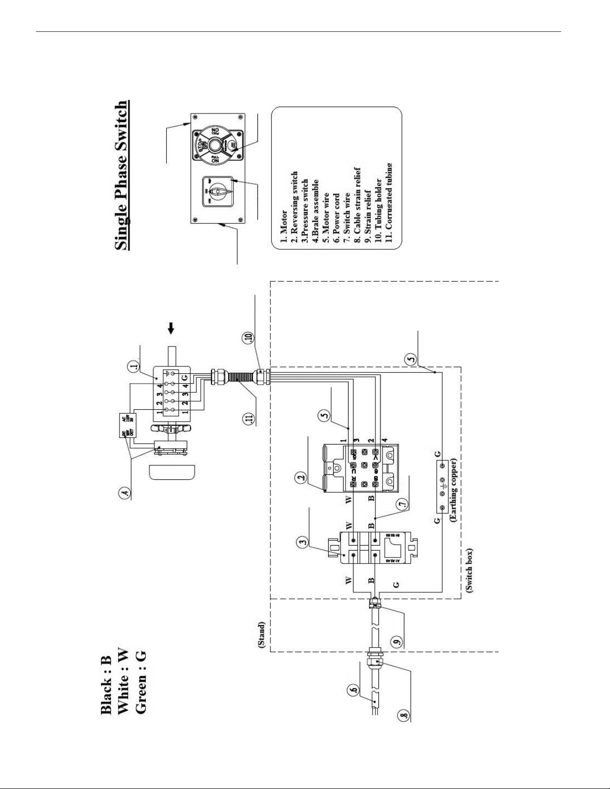
WIRING DIAGRAM - MODEL 9681314 - 16” DISC SANDER
Motor wire outlet
Power cord
outlet
Reversing Switch
Pressure
Switch
WIRING DIAGRAM - MODEL 9681310 - 16” DISC SANDER

11
NO SE Operating Manual & Parts List 9681310 & 9681311
11
WIRING DIAGRAM - MODEL 9681315 - 20” DISC SANDER
WIRING DIAGRAM - MODEL 9681311 - 20” DISC SANDER
12
NO SE Operating Manual & Parts List 9681310 & 9681311
14
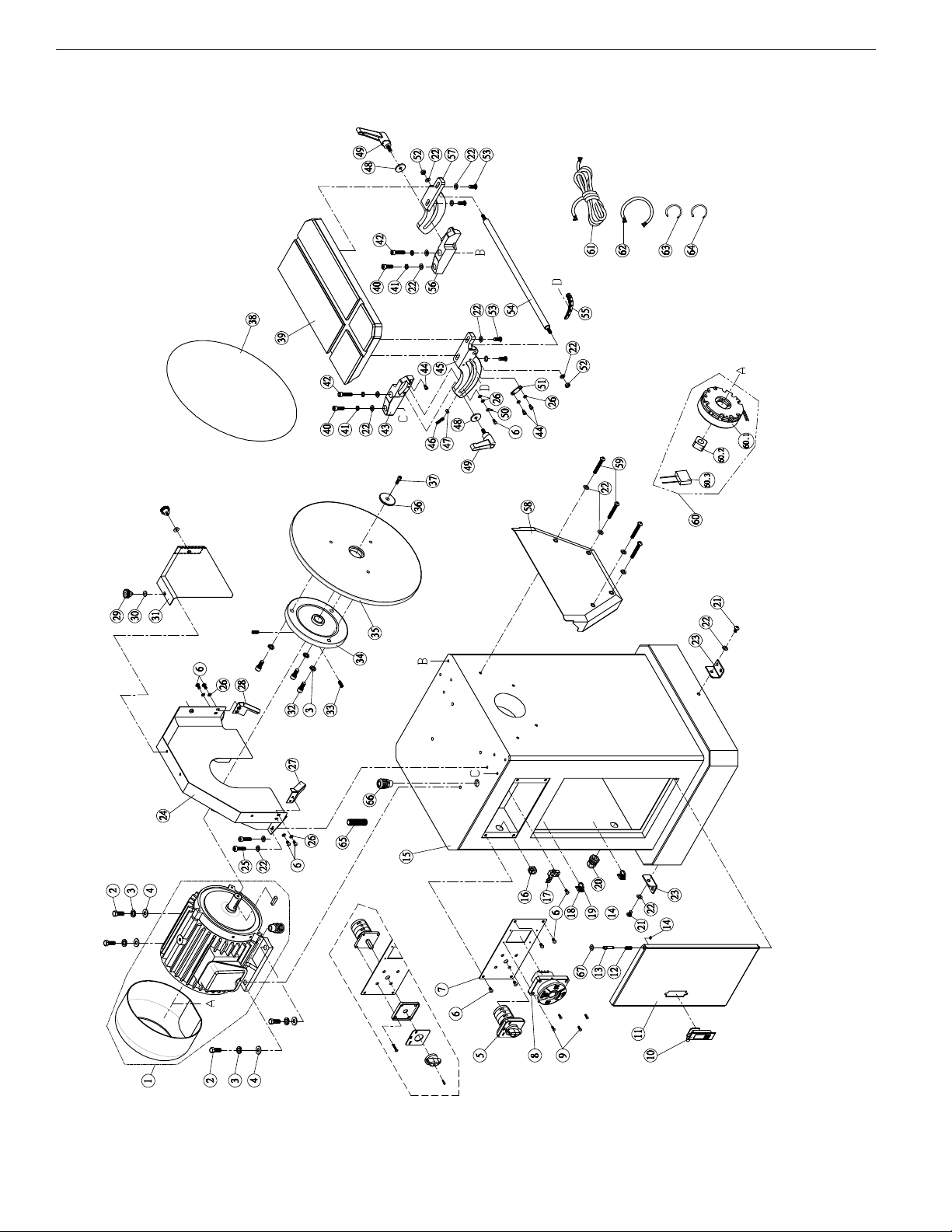
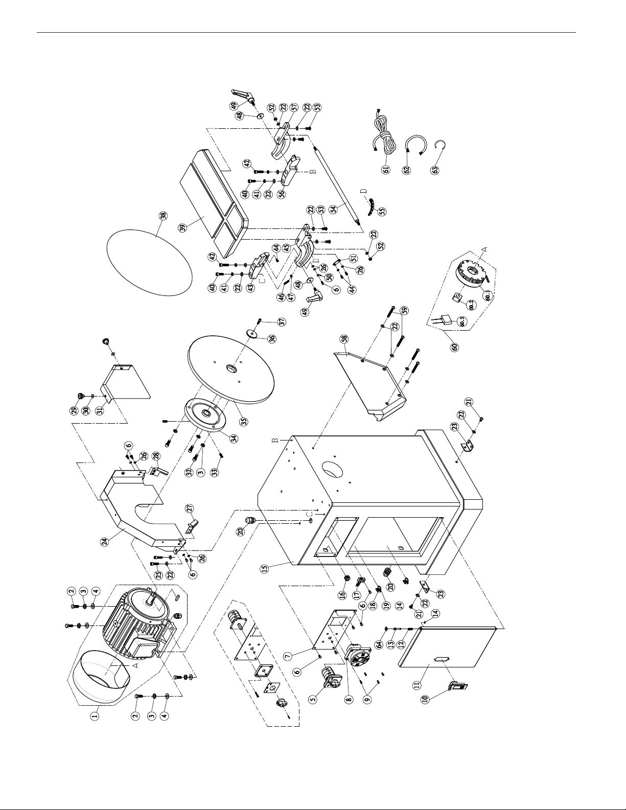
REPAIR PARTS ILLUSTRATION FOR MODEL 9681314 - 16” DISC SANDER
F
REPAIR PARTS ILLUSTRATION - MODEL 9681310 - 16” DISC SANDER

13
NO SE Operating Manual & Parts List 9681310 & 9681311
15
REPAIR PARTS LIST FOR MODEL 9681314 - 16” DISC SANDER
(6) Not Shown (*) Standard hardware item available locally (N/A) Not available as replacement part
1 Motor (1.5HP, 115V, 60Hz, 1PH, 4P) 9642598.01
1
2 Hex Screw (M10 x 1.5P x 25L ) * 4
3 Spring Washer (M10) * 7
4 Flat Washer (10.2 x 23 x 2t) *
4
5 Reversing Switch 9642599.01
1
6 Round Head Screw
(M5 x 1.0P x 12L)
*10
7 Switch Mount 9642600.01 1
8 Pressure Switch
(125V/35A 250V/20A)
9642601.01 1
9 Round Head Screw
(M4 x 0.7P x 12L)
*4
10 Door Buckle 9642602.01
1
11Door 9642603.011
12 Spring 9642604.01 1
13 Pin 9642605.01 1
14 E ring (ETW-4) * 1
15 Stand N/A 1
16 Strain Relief (SB8R-3) * 1
17 Ground Copper (3P) 9642606.01 1
18 Bracket 9642607.01 2
19 Wire Holder (ALT-165S 2.5Wx160L) 9642608.01 2
20 Cable Strain Relief (PG-13.5) 9642653.01 2
21 Round Head Screw (M8 x 1.25 x 12L) * 3
22 Flat Washer (8.2 x 16 x 1t) * 19
23 Anti-vibration Pad Bracket 9642609.01 3
24 Disc Guard 9642610.01 1
25 Cap Screw (M8 x 1.25 x 10L) *
4
26 Flat Washer (5.1 x 10 x 1t) *
8
27 Dust Chute Plate, Left 9642611.01 1
28 Dust Chute Plate, Right 9642612.01 1
29 Knob 9642613.01 2
30 Flat Washer (5.2 x 16 x 1.4t) * 2
31 Disc Guard, Front 9642614.01 1
32 Cap Screw (3/8"-16 UNC x 7/8"L ) * 3
33 Set Screw (5/16"-18 UNC x 3/4"L ) *
2
34 Hub 9642615.01
1
35 16" Disc 9642616.01 1
36 Wheel Washer 9642617.01 1
37 Cap Screw (1/4"-20 UNC x 3/4"L ) * 1
38 Abrasive Disc * 1
39 Table 9642619.01 1
40 Cap Screw (M8 x 1.25P x 30L) * 2
41 Spring Washer (M8) * 4
42 Cap Screw (M8 x 1.25P x 35L ) * 2
43 Trunnion Bracket, Left 9642620.01 1
44 Cap Screw(M5 x 0.8P x 8L) * 3
45 Trunnion, Left 9642621.01 1
46 Set Screw (M6 x 1.0P x 25L ) * 1
47 Hex Nut (M6 x 1.0P) * 1
48 Flat Washer (8 x 30 x 3t) * 2
49 Adjustment Knob (M8 x 1.25P x 20L) 9642622.01 2
Ref.
No. Description Part No. Qty.
Ref.
No. Description Part No. Qty.
50 Pointer 9642623.01 1
51 Angle Adjustment Plate 9642624.01 2
52 Hex Nut (M8 x 1.25P) * 2
53 Round Head Screw (M8 x 1.25 x 20L) * 4
54 Tie Rod 9642625.01 1
55 Angle Scale 9642626.01 1
56 Trunnion Bracket, Right 9642627.01 1
57 Trunnion, Right 9642628.01 1
58 Dust Chute 9642629.01 1
59 Round Head Screw (M8 x 1.25 x55L) * 4
60 Brake Assembly 9642630.01 1
60.1 Brake (9CB-18E) 9642631.01 1
60.2 Brake Block 9642632.01 1
60.3 5HFWL¿HU,1$&9287'&9 9642633.01 1
61 Motor Wire (14AWGx4Cx45cm) 9642634.01 1
62 Power cord (SJT 14AWG x 3C x
300cm + 110V(CSA))
9642635.01 1
63 Switch Wire (14AWG x 2C x 20cm) 9642636.01 1
64 Ground Cord
((600V) 14AWG x 1Cx60cm)
9642637.01 1
65 Hose NGN-12B 3/8" x 8cm 9642638.01 1
66 Strain Relief
(N-MGN20-15B-ST M20 x 1.5P)
*2
67 Foam washer * 1
REPAIR PARTS LIST - MODEL 9681310 - 16” DISC SANDER
14
NO SE Operating Manual & Parts List 9681310 & 9681311
16
REPAIR PARTS ILLUSTRATION FOR MODELS 9681315, 9681316 AND 9681317 -
20” DISC SANDERS
REPAIR PARTS ILLUSTRATION - MODEL 9681311 - 20” DISC SANDER

15
NO SE Operating Manual & Parts List 9681310 & 9681311
17
REPAIR PARTS LIST FOR MODEL 9681315, 9681316 AND 9681317 - 20” DISC SANDERS
(6) Not Shown (*) Standard hardware item available locally (N/A) Not available as replacement part
1 Motor Model 9681315
(2HP, 230V, 60Hz, 1PH)
9642642.01
1
1Motor Model 9681316
(3HP, 230V, 60Hz, 3PH)
9642641.01
1
1 Motor Model 9681317
(3HP, 460V, 60Hz, 3PH)
9642685.01
1
2 Hex Screw (M10 x 1.5P x 25L ) * 4
3 Spring Washer M10) * 7
4 Flat Washer (10.2 x 23 x 2t ) * 4
5 Reversing Switch 9642643.01
1
6 Round Head Screw
(M5 x 1.0P x 12L )
*
10
7 Switch Mount 9642644.01 1
8 Pressure Switch 9642645.01 1
9 Round Head Screw
(M4 x 0.7P x 12L )
*4
10 Door Buckle 9642602.01 1
11Door 9642603.01
1
12 Spring 9642604.01 1
13 Pin 9642605.01 1
14 E Ring (ETW-4 ) * 1
15 Stand N/A 1
16 Strain Relief (SB8R-3) * 1
17 Earthing copper (3P) 9642606.01 1
18 Bracket 9642607.01 2
19 Wire Holder (ALT-165S 2.5W x 160L) 9642608.01 2
20 Cable Strain Relief (PG-13.5) 9642653.01 2
21 Round Head Screw
(M8 x 1.25 x 12L )
*3
22 Flat Washer (8.2 x 16 x 1t ) * 19
23 Anti-vibration Pad Bracket 9642609.01 3
24 Disc Guard 9642655.01 1
25 Cap Screw (M8 x 1.25P x 10L ) * 4
26 Flat Washer (5.1 x 10 x 1t ) *
8
27 Dust Chute Plate, Left 9642656.01
1
28 Dust Chute Plate, Right 9642657.01 1
29 Knob 9642613.01 2
30 Flat Washer (5.2 x 16 x 1.4t) * 2
31 Disc Guard, Front 9642659.01 1
32 Cap Screw (3/8"-16 UNC x 7/8"L) * 3
33 Set Screw (5/16"-18 UNC x 3/4"L ) * 2
34 Hub 9642615.01
1
35 20" Disc 9642661.01
1
36 Disc Washer 9642617.01 1
37 Cap Screw (1/4"-20UNC x 3/4"L ) * 1
38 Abrasive Disc (20"#100) * 1
39 Table 9642663.01 1
40 Cap Screw (M8 x 1.25P x 30L ) * 2
41 Spring Washer (M8) * 4
42 Cap Screw (M8 x 1.25P x 35L) * 2
43 Trunnion Bracket, left 9642620.01 1
44 Cap Screw (M5 x 0.8P x 8L ) * 3
Ref.
No. Description Part No. Qty.
Ref.
No. Description Part No. Qty.
45 Trunnion, Left 9642621.01 1
46 Set Screw (M6 x 1.0P x 25L ) * 1
47 Hex Nut (M6 x 1.0P) * 1
48 Flat Washer (8 x 30 x 3t) * 2
49 Adjustment Knob (M8 x 1.25P x 20L) 9642622.01 2
50 Pointer 9642623.01 1
51 Angle Adjustment Plate 9642624.01 2
52 Hex Nut (M8 x 1.25P) * 2
53 Round Head Screw (M8 x 1.25 x 20L) * 4
54 Tie Rod 9642669.01 1
55 Angle Scale 9642626.01 1
56 Trunnion Bracket, Right 9642627.01 1
57 Trunnion, Right 9642628.01 1
58 Dust Chute 9642673.01 1
59 Round Head Screw (M8 x 1.25 x 55L) * 4
60 Brake Assembly 9642674.01 1
60.1 Brake (CB-18E) 9642675.01 1
60.2 Brake Block 9642632.01 1
60.3 5HFWL¿HU,1$&9287'&9 9642677.01 1
61 Motor Wire 9642678.01 1
62 Power Cord 9642679.01 1
63 Switch Wire 9642680.01 1
64 Foam Washer * 1
REPAIR PARTS LIST - MODEL 9681311 - 20” DISC SANDER

16
NO SE Operating Manual & Parts List 9681310 & 9681311
REPAIR PARTS ILLUSTRATION FOR MITER GAUGE,
MODELS 9681314, 9681315 AND 9681316 - DISC SANDERS
REPAIR PARTS ILLUSTRATION FOR MITER GAUGE -
MODELS 9681310 & 9681311 - DISC SANDERS

17
NO SE Operating Manual & Parts List 9681310 & 9681311
19
REPAIR PARTS LIST FOR MITER GAUGE - 9681314, 9681315, 9681316 AND 9681317 -
DISC SANDERS
(6) Not Shown (*) Standard hardware item available locally (N/A) Not available as replacement part
1Miter Gauge Assembly 9642639.01
1
1.1 Handle N/A 1
1.2 Miter Gauge N/A 1
1.3 Round Head Screw
(3/16"-24 UNC x 5/16"L )
N/A
1
Ref.
No. Description Part No. Qty.
Ref.
No. Description Part No. Qty.
1.4 Flat Washer (95.1 x 12 x 1.0t ) N/A
1
1.5 Pointer N/A 1
1.6 Bar N/A 1
1.7 Washer N/A 1
1.8 Phillips Screw
(1/4"-20 UNC x 5/16"L )
N/A 1
REPAIR PARTS LIST FOR MITER GAUGE -
MODELS 9681310 & 9681311 - DISC SANDERS

NOTES
18
NO SE Operating Manual & Parts List 9681310 & 9681311

NOTES
19
NO SE Operating Manual & Parts List 9681310 & 9681311

NO SE Operating Manual & Parts List 9681310 & 9681311
NO SE - a C.H. Hanson brand
2000 N. Aurora d., Naperville, IL 60563 U.S.A.
or call: 1-800-827-3398
NO SE by C.H. Hanson warrants their products to be free of defects in material or workmanship. This
warranty does not cover defects due directly or indirectly to misuse, abuse, normal wear and tear, failure
to properly maintain the product, heated, ground or otherwise altered, or used for a purpose other than
that for which it was intended.
The warranty does not cover expendable and/or wear part (i.e. v-belts, screws, abrasives, jaws), damage to
tools arising from alteration, abuse or use other than their intended purpose, packing and freight. The
duration of this warranty is expressly limited to the terms noted below beginning from the date of
delivery to the original user.
The NO SE branded items carry the following warranties on parts:
All NO SE branded Tools and Accessories 1 YEA
The obligation of NO SE by C.H. Hanson is limited solely to the repair or replacement, at our option, at its
factory or authorized repair agent of any part that should prove inoperable. Purchaser must lubricate and
maintain the product under normal operating conditions at all times. Prior to operation become familiar
with product and the included materials, i.e. warnings, cautions and manuals.
Failure to follow these instructions will void the warrant .
This warranty is the purchaser's exclusive remedy against C. H. Hanson for any inoperable parts in its
product. Under no circumstances is C. H. Hanson liable for any direct, indirect, incidental , special or
consequential damages including loss of profits in any way related to the use or inability to use our
products. This warranty gives you specific legal rights which may vary from state to state.
SERVICE & REPAIR
1. If a NO SE product requires a repair or warranty service DO NOT return the product to
the place of purchase.
2. All warranty related work must be evaluated and approved by NO SE.
3. Prior to returning any item the user must obtain factory approval and a valid GA number.
4. For instructions and GA number call toll free (800) 827-3398.
NORSE WARRANTY
18-0307
This manual suits for next models
1
Table of contents
Other CH Hanson Sander manuals


Popular Sander manuals by other brands


ULTRA TEC
ULTRA TEC ULTRAPOL Advance user manual

Far Tools
Far Tools BS 1200B Original manual translation

Central Pneumatic
Central Pneumatic 68152 Owner's manual and safety instructions

Toolshop
Toolshop 241-9801 Operator's manual

NUTOOL
NUTOOL RED NEP1200R Original Operating Instruction

Power Tec
Power Tec OS1000 owner's manual

Lumberjack
Lumberjack EBS100VS Safety and operating manual

Central Pneumatic
Central Pneumatic 42966 Assembly and operating instructions

Parkside
Parkside PEXS 270 C3 Translation of the original instructions

Triton
Triton TROS 125 Operating/safety instructions

Sthor
Sthor 79307 Original instructions

Ryobi
Ryobi CRO-180M user manual