Supplied By www.heating spares.co Tel. 0161 620 6677
installation
The BRITOIW II T is supplied in two cartons, on containing
the heater, the other containing the balanced ffue set.
INSTALLING THE BALANCED FLUE
The standard flue set is suitable for walls having a thickness of
75 mm (3 in) to 355 mm (14 in). An optional flue set for wall
thicknesses up to 500 mm (20 in) is available to special order.
DetaiIed recommandations for flueing are given in BS 5440 :
1. The following notes are for general guidance only.
The heater must be installed so that the ffue terminal is exposed
to the external air. The heater must not be installed so that the
terminal discharges into another room or space such as an
outhouse or lean-to.
Termination should be on a clear expanse of wall, the terminal
preferably being not less than 300 mm (1 ft.) away from a cor-
nern recess or projection.
DO
NOT install the terminal :
a) within 300 mm (1 ft.) measured vertically from the bottom of
an openable window, air vent or any other ventilation ope-
ning.
b) within 300 mm (lft.) above adjacent ground level.
c) within 600 mm (1 ft.) of any surface facing the terminal.
d) immediately beneath eaves or a balcony.
Where the lowest part of the terminal is less than 2 m ( 6,5 ft.)
above the level of any ground, balcony, ffat roof or place to
which any person has access, and which adjoints the wall in
which the terminal is situated, the terminal must be protected by
a guard of durable material. (A terminal guard is available from
QUINNELLBARRETT&QUINNELL,071639 1357.
The air inlet, product outlets duct or terminal of the heater must
not be closer than 50 mm (2 in) to any combustible material.
Detailed recommandations on the protection of combustible
material are given in BS 5440 : 1
PREPARING THE WALL
The heater should be installed on a wall of flat non- combustible
material that will not reverberate. Whatever the thickness of the
wall, make a hole 305 mm (12 in) wide by 205 mm
(8 in) high. If the hole is cut accurately there is no need to line it
as the wall liner will seal off the cavity.
A minimum clearance of 80 mm (3,2 in) should be left above
the top edge of the wall opening. For dimensions and clearance
see page 2 and Technical Data, page 3.
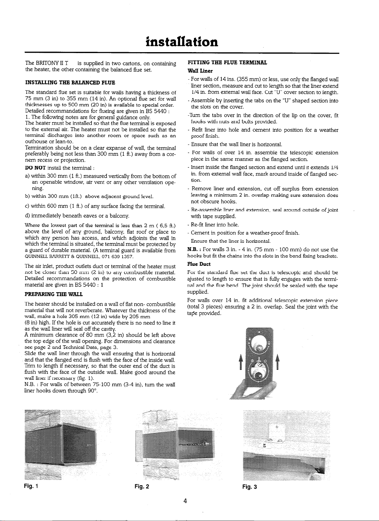
Slide the wall liner through the walI ensuring that is horizontal
and that the flanged end is flush with the face of the inside wall.
Trim to length if necessary, so that the outer end of the duct is
flush with the face of the outside wall. Make good around the
wall liner if necessary (fig. 1).
N.B. : For walls of between 75-100 mm (3-4 in), turn the wall
liner hooks down through 90”.
FITTING THE FLUE TERMINAL
Wall Liner
- For walls of 14 ins. (355 mm) or less, use onIy the flanged wall
liner section, measure and cut to length so that the liner extend
l/4 in. from external wall face. Cut “II” cover section to length.
- Assemble by inserting the tabs on the “U” shaped section into
the slots on the cover.
-Turn the tabs over in the direction of the lip on the cover, fit
hooks with nuts and bolts provided.
- Refit liner into hole and cement into position for a weather
proof finish.
- Ensure that the wall liner is horizontal.
- For walls of over 14 in. assemble the telescopic extension
piece in the same manner as the flanged section.
- Insert inside the flanged section and extend until it extends 114
in. from external wall face, mark around inside of ffanged sec-
tion.
- Remove liner and extension, cut off surplus from extension
leaving a minimum 2 in. overlap making sure extension does
not obscure hooks.
- Re-assemble liner and extension, seal around
with tape supplied.
- Re-fit liner into hole.
- Cement in position for a weather-proof iinish.
- Ensure that the liner is horizontal.
outside of joint
N.B. :
For walls 3 in. - 4 in. (75 mm - 100 mm) do not use the
hooks but fit the chains into the slots in the bend fting brackets.
Flue Duct
For the standard iIue set the duct is telescopic and should be
ajusted to length to ensure that is fully engages with the termi-
nal and the flue bend. The joint should be sealed with the tape
supplied.
For walls over 14 in. fit additional telescopic extension piece
(total 3 pieces) ensuring a 2 in. overlap. Seal the joint with the
tape provided.
4