Chamberlain LiftMaster 915LM User manual

CLOSED
OPEN
Indoor Receiver
AC Adapter
Sensor
CR2032
3 VOLTS
Lithium Battery
(CR2032 type) Double-Sided
Fastening Strip
To prevent possible SERIOUS INJURY or DEATH from a closing garage
door:
• Activate door ONLY when it can be seen clearly, is properly adjusted,
and there are no obstructions to door travel.
• ALWAYS keep garage door in sight until completely closed. NEVER
permit anyone to cross path of closing garage door.
WARNING
CAUTION
WARNING
WARNING
GARAGE DOOR
MONITOR SYSTEM
PRE-INSTALLATION SYSTEM TEST
1. The sensor and receiver are pre-matched (programmed) at the
factory. Test the system by flipping the sensor over while it is a
few feet away from the receiver. The receiver will show a
green light for closed when the sensor is face up in the vertical
position with the round end of the case pointing down
(Figure 1). The red light will flash when the sensor is face
down in the horizontal position (Figure 2).
2. If the green or the red receiver lights do not come on, or do
not react as described, see the Troubleshooting or Learning
section of these instructions.
INSTALLING THE BATTERY IN THE GARAGE
DOOR INDICATOR SENSOR
1. Place the screw driver blade on the tab at
the end of the case and gently press down
and in toward the case.
2. Insert the the lithium battery into the battery
clip with the + (positive) side face up.
3. Push the case back together tightly by
inserting the top hooks into the back cover,
then snap shut the bottom of the case.
NOTE: It is normal to hear a rattle from the tilt
switch in the sensor when tilted or rotated to
another position.
INDOOR RECEIVER SETUP
1. Plug the AC adapter into any
standard 110 volt AC electrical
wall outlet and the small plug
into the back of the indoor
receiver.
2. The receiver has a 9" antenna
wire which comes out the back.
The antenna should be straight
and not touching metal.
3VOLTS
Figure 1 Figure 2
NOTE: Because radio control devices are inherently susceptible
to RF interference, this product should NOT be used as a
stand-alone security device. This product is considered a
monitoring and notification device ONLY, and as such, should not
be used as a substitute for a dedicated home security system.
To ensure that your Garage Door Monitor continues to operate
properly, the following checks should be performed on a
monthly basis:
• Check that the sensor is mounted properly on the garage door
(see Mounting the Sensor section of this manual.)
• Ensure the 3 volt lithium battery is installed properly.
• Check to see that the receiver system is plugged into a wall
outlet and the jack is properly connected to the back of the
receiver. Make sure the antenna is straight and not in contact
with any metal objects.
• Check that the receiver is properly recognizing sensor
signals (see Troubleshooting section of this manual.)
CLOSED
OPEN
Antenna Learn
Button
AC
Adapter
Location
MOUNTING THE SENSOR
Attach the sensor to the inside of the garage door using the
double-sided fastening strip. Mount the sensor near the top of the
garage door for best results. The round end of the case should
be pointing down when the garage door is closed.
Inside of Garage
Double-Sided Fastening Strip
Round End
Down
Know when your garage door is open
or closed!
Thank you for purchasing the LiftMaster Garage Door Monitor.
Monitor the status of your garage door from inside your home. No
longer will you have to run downstairs or go outside just to see if
you or your children have left the garage door open.
Garage Door Monitor
Models 915LM • 916LM • 2C507-2

GARAGE DOOR MONITOR OPERATION
When the receiver is powered up, both red and green LED’s
will blink once. The receiver will then show a solid green LED
until it receives a signal from a programmed sensor. The receiver
will display the current status of the programmed door sensor. If
no door sensor(s) is programmed to the receiver, the green and
red LED will flash simultaneously. See Learning section.
The sensor sends a closed signal when the garage door is
closed (vertical) and an open signal as the sensor changes to
open (horizontal) position.
Up to 4 door mounted sensors will work in conjunction with one
receiver.
The red LED will blink once every half-second if one or more of
the programmed sensors are not in the closed position. The
green LED comes on steady only when all the programmed
sensors are in the closed position.
NOTE: The system will sometimes take a few seconds to send a
signal. The sensor updates the receiver by transmitting an open
or closed signal every few minutes.
LEARNING MORE THAN ONE SENSOR(S)
1. Door must be closed and the green
LED on steadily.
2. Press and hold the learn button for 2
seconds, the receiver will enter the learn
mode. The green LED will blink on and off
in 1/2 second increments.
3. The additional sensor(s) must be moved
from a vertical position to a horizontal
position or vice versa.
4. Both green and red LED’s will turn on for 1 second to indicate
a successful learn. Upon success, the receiver immediately
exits the learn mode and returns to normal operation.
5. If no signal is received within 30 seconds, the receiver will exit
the learn mode and return to normal operation.
ERASING OR CLEARING THE MEMORY
1. Unplug the small plug from the AC adapter on the
indoor receiver.
2. Make sure the AC adapter is plugged into a wall outlet.
3. To erase the memory of all programmed sensors, press and
hold the learn button while plugging the small plug on the AC
adapter into the indoor receiver.
4. Both red and green LED’s will blink simultaneously. This also
indicates that no sensor(s) are in memory.
5. Proceed to Step 2 of Learning More Than One Sensor to
program the sensor to the receiver.
TROUBLESHOOTING
The sensor battery must be replaced every year to assure
consistent operation. Flashing of the red and green LED’s in a
special sequence normally indicates intermittent operation or a
dead battery.
Loss of signal: The sensor sends a signal periodically to
synchronize to the receiver. Should the receiver not receive the
signal in approximately 20 minutes, the red and green LED’s will
blink as follows. The green LED will blink once, then the red LED
will blink one to four times depending upon the sensor
number. This indicates the receiver has not received the signal
from this sensor for over 20 minutes and therefore
requires attention.
If replacing the battery does not rectify the issue, move the
receiver into the garage for additional troubleshooting. If the
monitor works flawlessly in close proximity, the sensor(s) signal is
being either blocked or interfered with in the previous location
and may require placement in a room closer to the garage
door(s).
Garage Door Monitor system just installed:
The sensor and receiver set are factory coded prior to shipment
and should work out of the package. If you encounter a situation
where the sensor and receiver work properly upon initial
installation, but show a loss of signal after 20 minutes you may
have an additional factory code in the receivers memory. In this
instance, the receiver will then appear to be unresponsive to the
sensor. In this instance, do the following:
1. Clear Receiver Memory – See Erasing or Clearing the
Memory section. Upon clearing memory, the receiver will
power up and show simultaneously flashing green and red
LED’s – this indicates that memory is cleared.
2. Proceed to Step 2 of Learning More Than One Sensor. Note
that the procedures to learn 1 sensor or multiple sensors are
the same.
If the receiver is still showing a loss of signal after following the
above procedure, then the receiver is located too far away from
the sensor. Relocate the receiver closer to the sensor.
Garage Door Monitor suddenly malfunctions after working
properly:
The sensors battery power is low. Replace the battery.
OPTIONAL ACCESSORIES
You can purchase additional sensors if you have more than one
garage door. The receiver will learn up to 4 sensors and the red
light will blink if any one of the garage doors is open.
ITEM PART #
Sensor 916LM
Indoor Receiver 2C507-2
12 Volt AC Adapter 2C508-2
Specifications:
Sensor
Battery: Lithium Type 2032. 1 year life.
Temperature: -180F to 1400F (-250C to 600C).
Codes: 254 randomly set codes.
Receiver
Power Supply: 12 volt DC, 50 mA.
Temperature: 140F to 1220F (-100C to 500C).
Codes: Learns codes of up to 4 sensors
FOR SERVICE DIAL OUR TOLL FREE NUMBER:
(U.S.A.): 1-800-528-2817
© 2004, Chamberlain Group Inc.
114A2627F All Rights Reserved
Press
and Hold
the Learn
Button
NOTICE: To comply with FCC and or Industry Canada (IC) rules, adjustment or modifications of
this receiver and/or transmitter are prohibited, except for changing the code setting or replacing
the battery. THERE ARE NO OTHER USER SERVICEABLE PARTS.
Tested to Comply with FCC Standards FOR HOME OR OFFICE USE. Operation is subject to the
following two conditions: (1) this device may not cause harmful interference, and (2) this device
must accept any interference received, including interference that may cause undesired operation.

CLOSED
OPEN
Receptor Interior
Adaptador de CA
Sensor
CR2032
3 VOLTS
Pila de Litio
(tipo CR2032) Tira Sujetadora de Dos Lados
SISTEMA DE MONITOREO
DE LA PUERTA DEL GARAJE
PRUEBA DE PREINSTALACIÓN DEL SISTEMA
1. El sensor y el receptor se hacen corresponder (programados) de
fábrica. Pruebe el sistema invirtiendo el sensor mientras está a unos
pocos pies del receptor. El receptor muestra una luz verde cuando
está cerrado cuando el sensor está orientado hacia arriba en la
posición vertical con el extremo redondo de la caja apuntando hacia
arriba (Figura 1). La luz roja centellea cuando el sensor está orientado
hacia abajo en la posición horizontal (Figura 2).
2. Vea la sección de Localización de Fallas o de Aprendizaje de estas
instrucciones, si las luces verde o de receptor roja no se encienden, o
no reaccionan según se describe.
INSTALACION DE LA PILA EN EL SENSOR
INDICADOR DE LA PUERTA DEL GARAJE
1. Coloque la hoja del destornillador en la aleta al
extremo de la caja y presione suavemente hacia
abajo y hacia adentro hacia la caja.
2. Inserte la pila de litio dentro del broche de la pila
con el lado + (positivo) hacia arriba.
3. Cierre bien la caja insertando los ganchos
superiores dentro de la cubierta posterior, a
continuación calce cerrada el fondo de la caja.
NOTA: Es normal escuchar un sonido metálico del
conmutador de inclinación en el sensor cuando está
inclinado o girado a otra posición.
PREPARACION DEL RECEPTOR INTERIOR
1. Enchufe el adaptador de CA dentro
de cualquier tomacorrientes
eléctrico de pared de 110 voltios de
CA y el enchufe pequeño dentro de
la parte inferior del receptor
Interior.
2. El Receptor tiene un cable de
antena de 9" que sale de la parte
posterior. La antena debe estar
recta y no tocar el metal.
3VOLTS
Figure 1 Figure 2
NOTA: A causa que los dispositivos de control por radio son
inherentemente susceptibles a la interferencia RF, este producto NO debe
usarse como un dispositivo de seguridad exclusivo. Este producto se
considera un dispositivo de monitoreo y notificación SOLAMENTE, y
como tal no debe usarse como un substituto para un sistema dedicado
de seguridad del hogar.
Deben efectuarse las inspecciones siguientes mensualmente, para
asegurar que el monitor de su puerta de garaje funcione apropiadamente:
• Inspeccione que el sensor esté montado apropiadamente en la puerta
del garaje (vea la sección de Montaje del sensor de este manual).
• Asegúrese que la pila de litio de 3 voltios esté instalada
apropiadamente.
• Inspeccione para verificar que el sistema receptor esté enchufado a un
tomacorrientes de pared y el jack esté conectado apropiadamente a la
parte posterior del receptor. Asegúrese que la antena esté recta y sin
contacto con objetos de metal.
• Verifique que el receptor reconozca apropiadamente las señales del
sensor (vea la sección de Localización de fallas de este manual.)
CLOSED
OPEN
Antena Botón de
Aprendizaje
Ubicación del
Adaptador
de CA
MONTAJE DEL SENSOR
Fije el sensor al interior de la puerta del garaje usando el tira sujetadora
de dos lados. Monte el sensor cerca del tope de la puerta del garaje para
obtener los mejores resultados. El extremo redondo de la caja debe
apuntar hacia abajo cuando la puerta del garaje está cerrada.
Interior Del Garaje
Tira Sujetadora de Dos Lados
Extremo Redondo
Orientado
Hacia Abajo
¡Sepa cuando la puerta del garaje está abierta
o cerrada!
Gracias por comprar el monitor de puerta de garaje LiftMaster. Vigile el
estado de la puerta de su garaje desde el interior de su casa. Nunca más
va a tener que bajar las escaleras o salir sólo para ver si sus niños han
dejado abierta la puerta del garaje.
Monitor de puerta de garaje
Models 915LM • 916LM • 2C507-2
Para prevenir una LESIÓN GRAVE o la MUERTE de una puerta cerrante de un
garage:
• Active la puerta SOLO cuando pueda verse claramente, esté bien ajustada, y no
hay obstrucciones al recorrido de la puerta.
• SIEMPRE mantenga la puerta del garage a la vista hasta que esté
completamente cerrada. NUNCA permita que nadie cruce el recorrido de la
puerta del garage mientras se está cerrando.
PRECAUCIÓN
ADVERTENCIA
ADVERTENCIA
ADVERTENCIA
ADVERTENCIA

OPERACION DEL MONITOR DE LA PUERTA
DEL GARAGE
Los LED rojo y verde centellean una vez, cuando el receptor está
activado. El LED verde del receptor permanecerá encendido, sin
centellear, hasta que el receptor reciba una señal de un sensor
programado. El receptor muestra el estado corriente del sensor
programado de la puerta. Si el sensor(es) de la puerta no está
programado al receptor, el LED verde y rojo centellean simultáneamente.
Vea la sección de Aprendizaje.
El sensor envía una señal cerrada cuando la puerta del garaje está
cerrada (vertical) y una señal abierta cuando el sensor cambia a la
posición abierta (horizontal).
Hasta 4 sensores montados en la puerta funcionan conjuntamente con un
receptor.
El LED rojo centellea una vez cada medio segundo si uno o más de los
sensores programados no están en la posición cerrada. El LED verde es
firme cuando todos los sensores programados están en la posición
cerrada.
NOTA: El sistema tarda a veces unos pocos segundos para enviar una
señal. El sensor actualiza el receptor transmitiendo una señal abierta o
cerrada cada pocos minutos.
APRENDIENDO MAS DE UN SENSOR(ES)
1. La puerta debe estar cerrada y el LED verde firme.
2. Oprima y mantenga el botón de aprendizaje
por 2 segundos, el receptor entra al modo de
aprendizaje. El LED verde centellea y se apaga
en incrementos de 1/2 segundo.
3. El sensor(es) adicional debe moverse desde
una posición vertical a una posición horizontal
o viceversa.
4. Ambos LED verde y rojo se encienden por 1
segundo para indicar un aprendizaje exitoso. Al
ser exitoso el receptor inmediatamente sale del
modo de aprendizaje y retorna a la operación normal.
5. Si no se recibe una señal dentro de 30 segundos, el receptor sale del
modo de salida y retorna a la operación normal.
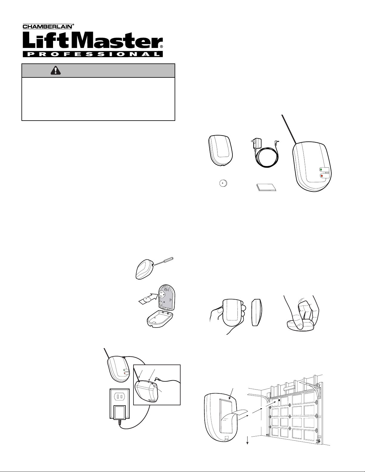
ELIMINACION O DESPEJE DE LA MEMORIA
1. Desconecte el enchufe pequeño del adaptador de CA en el receptor
interior.
2. Asegúrese que el adaptador de CA está enchufado a un
tomacorrientes de pared.
3. Para eliminar la memoria de todos los sensores programados, oprima
y mantenga el botón de aprendizaje mientras conecta el enchufe
pequeño en el adaptador de CA dentro del receptor interior.
4. Ambos LED´s rojo y verde centellean simultáneamente. Esto indica
también que no hay un sensor(es) en la memoria.
5. Proceda al Paso 2 de Aprendiendo mas de un Sensor(es) (Aprendizaje
de más de un sensor) para programar el sensor al receptor.
LOCALIZACION DE FALLAS
La pila del sensor debe reemplazarse cada año para asegurar una
operación consistente. El centelleo del LED rojo y verde en una
secuencia especial indica normalmente una operación intermitente o una
pila agotada.
Pérdida de señal: El sensor envía una señal periódicamente para
sincronizar al receptor. Si el receptor no recibe la señal en 20 minutos
aproximadamente, los LED rojo y verde centellean como sigue. El LED
centellea una vez, a continuación el LED rojo centellea entre una y cuatro
veces dependiendo del número del sensor. Esto indica que el receptor no
ha recibido la señal de este sensor por más de 20 minutos y por
consiguiente requiere atención.
Si el reemplazo de la pila no rectifica el problema, mueva el receptor al
garaje para una localización adicional de fallas. Si el monitor funciona
perfectamente en una proximidad estrecha, la señal del sensor(es) está
siendo bloqueada o interferida en la ubicación previa y puede requerir
reemplazar en un cuarto más cercano a la puerta(s) del garaje.
Sistema de monitor de puerta abierta del garaje recién instalado:
El conjunto de sensor y receptor fue programado en la fábrica antes del
envío y debería funcionar tal como usted lo recibe. Si el sensor y el
receptor funcionan bien después de la instalación inicial, pero se produce
una pérdida de señal después de unos 20 minutos, es posible que haya
un código de fábrica adicional en la memoria del receptor. Para el sensor,
esta situación implica que el receptor no funciona. Para solucionar este
problema, proceda de la manera siguiente:
1. Despeje la memoria del receptor. Vea la sección Eliminación o
Despeje de la Memoria. Una vez despejada la memoria, el receptor
se activará y los LED rojo y verde centellearán simultáneamente para
indicar que se ha despejado la memoria.
2. Proceda al paso 2 de la sección Aprendiendo más de un Sensor(es).
Tenga en cuenta que se sigue el mismo procedimiento para
programar uno o varios sensores.
Si el receptor sigue experimentando una pérdida de señal después de
haberse seguido el procedimiento anterior, el receptor está demasiado
lejos del sensor. Coloque el receptor más cerca del sensor.
El monitor de la puerta del garaje funciona mal repentinamente
después de funcionar bien:
La pila del sensor está débil. Reemplace la pila.
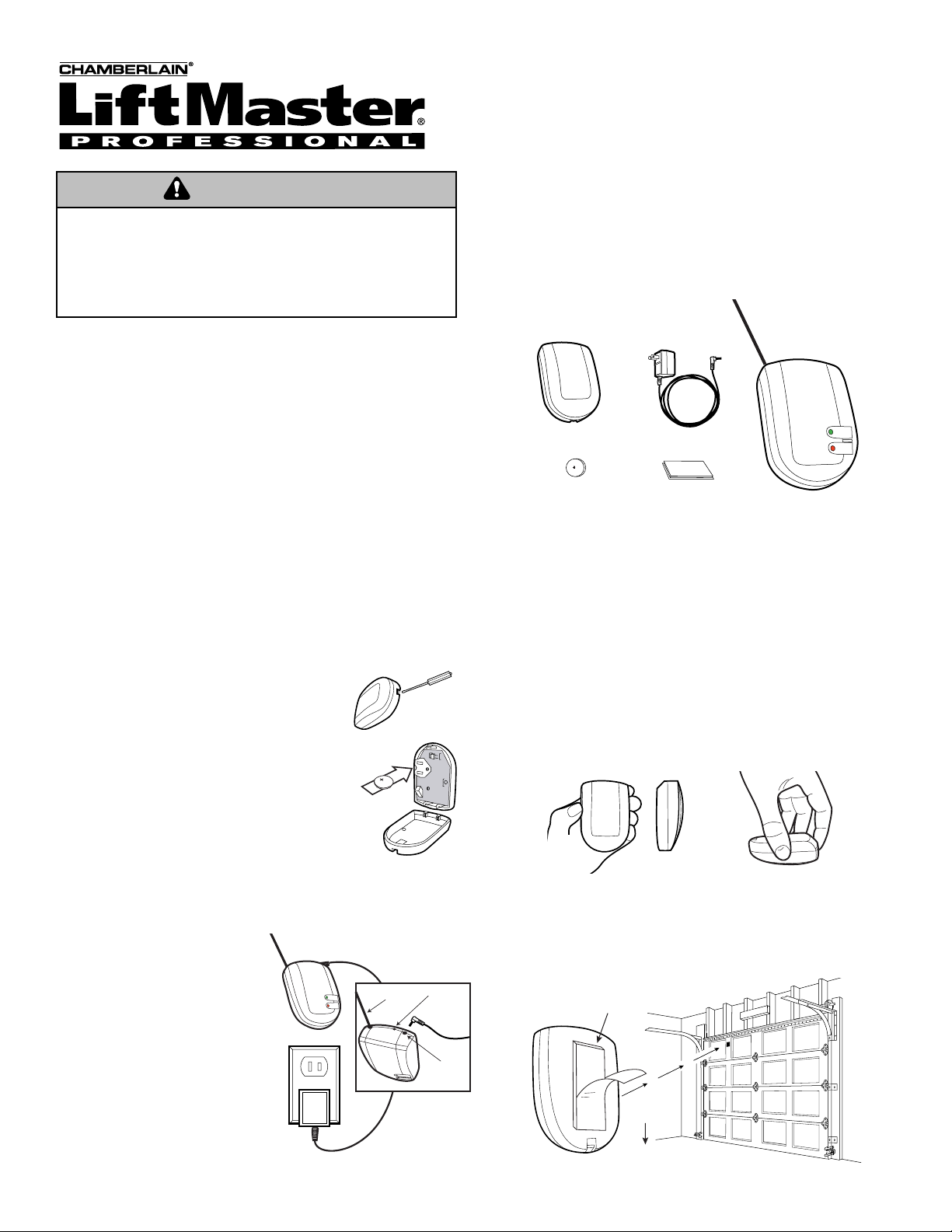
ACCESORIOS OPCIONALES
Usted puede comprar sensores adicionales si tiene más
de una puerta de garaje. El receptor aprende hasta 4 sensores y la luz
roja centellea si alguna de las puertas del garaje está abierta.
ITEM Nº DE PIEZA
Sensor 916LM
Receptor Interno 2C507-2
Adaptador de 12 voltios de CA 2C508-2
Especificaciones:
Sensor
Pila: Litio Tipo 2032. 1 año de duración.
Temperatura: -18ºF a 140ºF (-25ºC a 60ºC).
Códigos: 254 códigos establecidos al azar.
Receptor
Alimentación Eléctrica: 12 Voltios de CC, 50 mA.
Temperatura: 14ºF a 122ºF (-10ºC a 50ºC).
Códigos Aprende los códigos de hasta
4 sensores.
PARA SERVICIO, LLAME NOSOTROS SIN COSTO:
(E.U.): 1-800-528-2817
© 2004, Chamberlain Group Inc.
114A2627F Todos los Derechos Reservados
Oprima y
Mantenga
el Botón de
Aprendizaje
AVISO: Para cumplir con las reglas de la FCC y/o de Canadá (IC), las reglas, ajustes o modificaciones
de este receptor y/o transmisor están prohibidos, excepto por el cambio de la graduación del código o el
reemplazo de la pila. NO HAY OTRAS PIEZAS REPARABLES DEL USUARIO.
Se ha probado para cumplir con las normas de la FCC para USO DEL HOGAR O DE LA OFICINA. La
operación está sujeta a las dos condiciones siguientes:(1) este dispositivo no puede causar interferencia
perjudicial, y (2) este dispositivo debe aceptar cualquier interferencia recibida, incluyendo la interferencia
que puede causar una operación no deseable.
This manual suits for next models
2
Table of contents
Languages:
Other Chamberlain Monitor manuals