manuals.online logo
Brands
  1. Home
  2. •
  3. Brands
  4. •
  5. Chamberlain
  6. •
  7. Remote Starter
  8. •
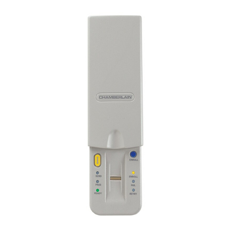
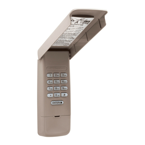
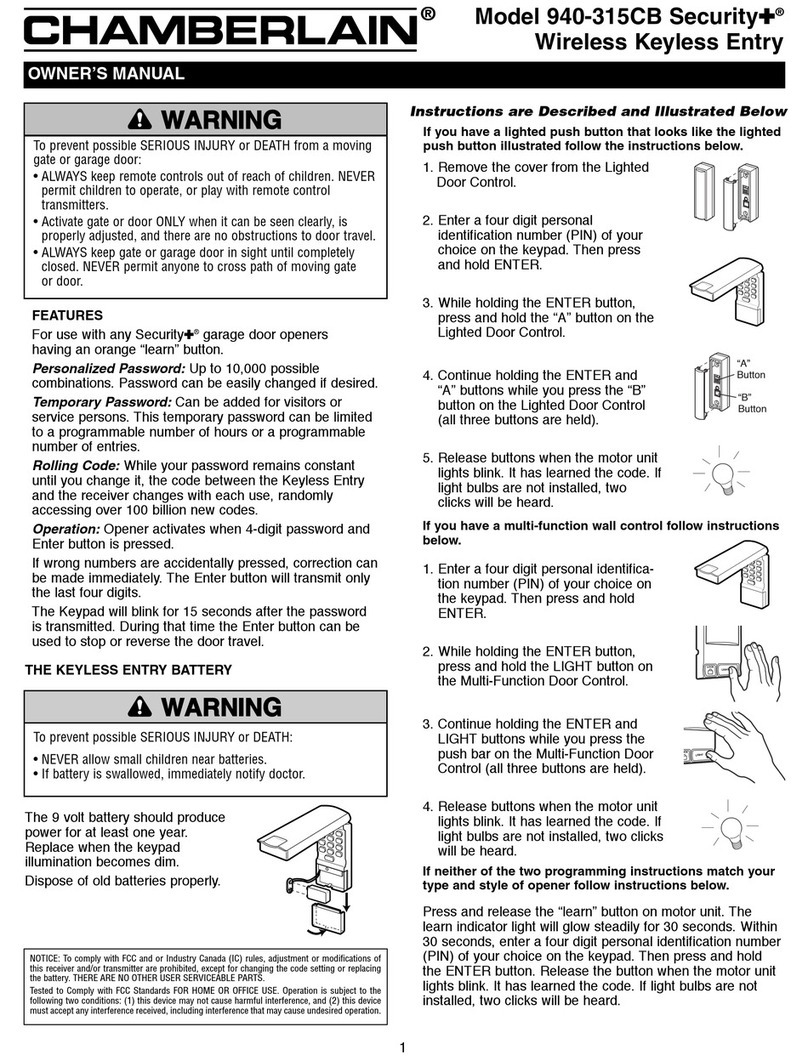
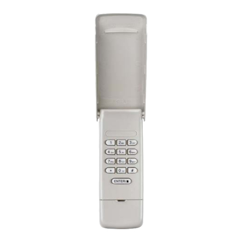
  9. Chamberlain 40 User manual

Chamberlain 40 User manual

This manual suits for next models

1

Other Chamberlain Remote Starter manuals

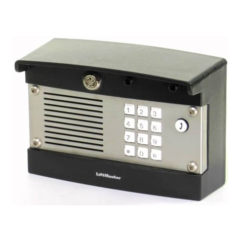
Chamberlain Security+ 940CD User manual

Chamberlain

Chamberlain Security+ 940CD User manual

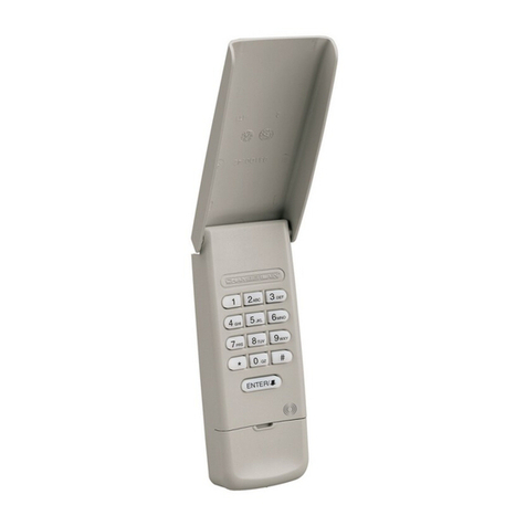
Chamberlain 976LM Security+ User manual

Chamberlain

Chamberlain 976LM Security+ User manual

Chamberlain LiftMaster Securty+ 976LM User manual

Chamberlain

Chamberlain LiftMaster Securty+ 976LM User manual

Chamberlain SECURITY+ 940-315CB User manual

Chamberlain

Chamberlain SECURITY+ 940-315CB User manual

Chamberlain 942FP-10 User manual

Chamberlain

Chamberlain 942FP-10 User manual

Chamberlain LiftMaster Professional 387LM User manual

Chamberlain

Chamberlain LiftMaster Professional 387LM User manual

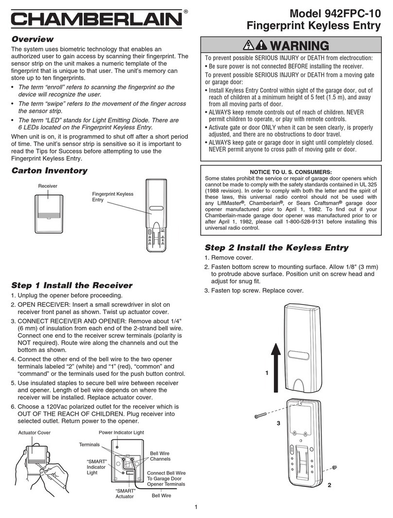
Chamberlain 942FPC-10 User manual

Chamberlain

Chamberlain 942FPC-10 User manual

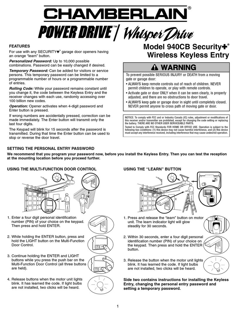
Chamberlain Security+ 940CB User manual

Chamberlain

Chamberlain Security+ 940CB User manual

Chamberlain LiftMaster Professional Security+ 376LM User manual

Chamberlain

Chamberlain LiftMaster Professional Security+ 376LM User manual

Chamberlain 878MAX User manual

Chamberlain

Chamberlain 878MAX User manual

Chamberlain 942FP User manual

Chamberlain

Chamberlain 942FP User manual

Chamberlain 940D-01 Guide

Chamberlain

Chamberlain 940D-01 Guide

Chamberlain 940EV-P2 User manual

Chamberlain

Chamberlain 940EV-P2 User manual

Chamberlain Security+ 377LG User manual

Chamberlain

Chamberlain Security+ 377LG User manual

Chamberlain 747E Series User manual

Chamberlain

Chamberlain 747E Series User manual

Chamberlain 940CD-01 User manual

Chamberlain

Chamberlain 940CD-01 User manual

Chamberlain 877MAX User manual

Chamberlain

Chamberlain 877MAX User manual

Chamberlain 727E Series User manual

Chamberlain

Chamberlain 727E Series User manual

Chamberlain 877MAX User manual

Chamberlain

Chamberlain 877MAX User manual

Chamberlain POWER DRIVE 940D User manual

Chamberlain

Chamberlain POWER DRIVE 940D User manual

Chamberlain LiftMaster TAC1 Assembly instructions

Chamberlain

Chamberlain LiftMaster TAC1 Assembly instructions

Chamberlain POWER DRIVE Whisper Drive 940CB User manual

Chamberlain

Chamberlain POWER DRIVE Whisper Drive 940CB User manual

Chamberlain LiftMaster 379LM User manual

Chamberlain

Chamberlain LiftMaster 379LM User manual

Chamberlain 940EV User manual

Chamberlain

Chamberlain 940EV User manual

Popular Remote Starter manuals by other brands

FamilyTool FMT002JST instruction manual

FamilyTool

FamilyTool FMT002JST instruction manual

PowerJump LMD-021 user manual

PowerJump

PowerJump LMD-021 user manual

AstroStart 803U user manual

AstroStart

AstroStart 803U user manual

Durite 0-649-20 Leaflet

Durite

Durite 0-649-20 Leaflet

Linear ACCESS AK-21 Installation and programming instructions

Linear

Linear ACCESS AK-21 Installation and programming instructions

Soundstream TARANTULA RS.2 installation guide

Soundstream

Soundstream TARANTULA RS.2 installation guide

Jaycar Electronics MB3752 instruction manual

Jaycar Electronics

Jaycar Electronics MB3752 instruction manual

Ultra Start 72 Series owner's manual

Ultra Start

Ultra Start 72 Series owner's manual

ADS FLASHLOGIC FLRSVW1 Product guide

ADS

ADS FLASHLOGIC FLRSVW1 Product guide

Black Widow Security BW RAS 400 installation manual

Black Widow Security

Black Widow Security BW RAS 400 installation manual

Vector Power City DK080706 Owner's manual & warranty

Vector

Vector Power City DK080706 Owner's manual & warranty

Code Alarm CA-535 owner's manual

Code Alarm

Code Alarm CA-535 owner's manual

EINHELL EGS 3600 Directions for use

EINHELL

EINHELL EGS 3600 Directions for use

Schumacher INSTANT POWER IP-75C owner's manual

Schumacher

Schumacher INSTANT POWER IP-75C owner's manual

EINHELL BT-PS 1000 Directions for use

EINHELL

EINHELL BT-PS 1000 Directions for use

Mazda 0000-8F-H28 installation instructions

Mazda

Mazda 0000-8F-H28 installation instructions

DEI 450ESP owner's guide

DEI

DEI 450ESP owner's guide

Directed Electronics AutoCommand 28624TN Owner's installation guide

Directed Electronics

Directed Electronics AutoCommand 28624TN Owner's installation guide

manuals.online logo
manuals.online logoBrands
  • About & Mission
  • Contact us
  • Privacy Policy
  • Terms and Conditions

Copyright 2025 Manuals.Online. All Rights Reserved.

Door Jamb
Face
Keyboard
1
3
5
7
9
2
4
6
8
*
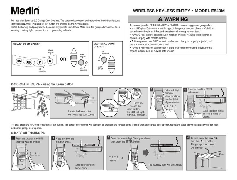
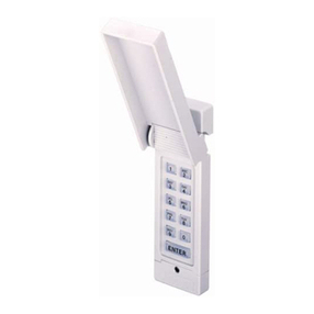
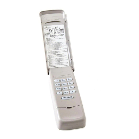
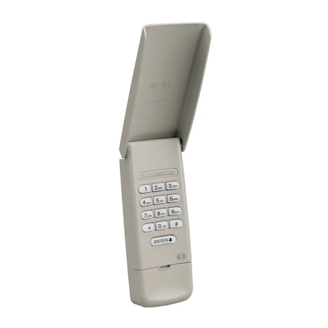
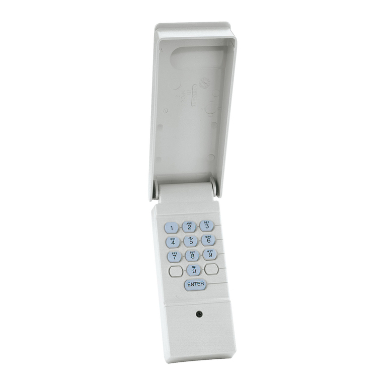
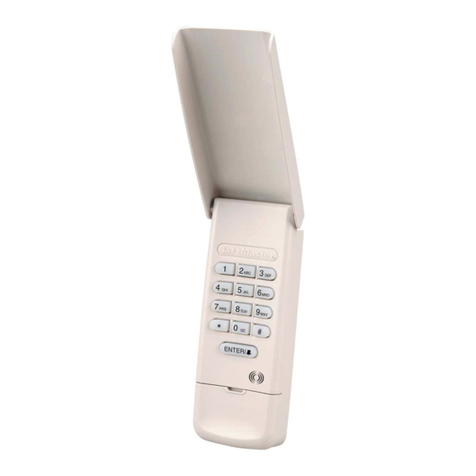
TheKeyless Entry System consists of akeyboard andaconsole. Thekeyboard sends acoded signal from outside thegarage. The
consolefastens toan inside garagewall. It receives the4-digit programmed coded signal andstarts thedoor opener.
The Keyless Entry System will work with most Genie “Push Twice to Operate" openers if you press any other digit after you
enter the 4-digit programmed code.
NOTE: Cable connector hole is located on left side of console. If possible, install keyless entry system on left side of garage
(determented by facing garage from outside). If installed on right side of garage, cable must be routed over or under console.
KEYBOARD CONSOLE
FEATURES OF THE OF KEYLESS ENTRY SYSTEM
Personalized Code: 10,000 possiblecombinations. Code can
be changed easilyif desired.
Operation: Opener activates when programmed code is
entered on thekeyboard.
Theuser has 10 seconds from thetime thefirst number is
pressed toenter the4-digit code.
If incorrect numbers are accidentallypressed, a5 second
interval is necessary before starting over.
Power Supply: Operates from thegaragedoor opener power
with abattery back-up for code memory andlighted keyboard.
Unit will not operatewithout battery.
Installation: SimpletoInstall in 5 easysteps.
Console: Provides an additional push button control tooperate
door from inside garage.
Keyboard: Thegaragedoor can be operated after avalidcode
entry by pressing anysinglekey as long as thekeyboard light
remains on.
Keyboard Illuminates andremains lit for 10 seconds when ANY
number is pressed. In darkness this feature allows user to
press anynumber before entering the4-digit code.
IMPORTANT NOTE: When Illumination is needed, avoid
pressing keyboard area which contains the first code number.
STEP 1—SECTIONAL DOORS: Draw twointersecting lines on
garagejamb face - horizontallyat eye level andverticallyas
closetocenterlineas possible. Makesure there is at least 1-1/4"
clearance on each side of thevertical Line. Drill a1" diameter
holethrough thejamb at marked location.
Refer toIllustration on Side 2 if yourgaragehas a
built-up jamb.
STEP 1—ONE-PIECE DOORS: Install thekeyboard on the
exterior front wall of aFRAME garage. Position it away from the
door opening toavoidinjury as door swings out andup. Drill a1"
diameter holethrough wall at eye level. Refer tonotebelow; then
proceed toStep 2.
PARTS LIST
ConsoleAssembl . . . . . . . . . . . . . . . . . . . . . . . . . . . . .41D2995
Keyboard Assembly. . . . . . . . . . . . . . . . . . . . . . . . . . .41D2994
9 Volt Battery . . . . . . . . . . . . . . . . . . . . . . . . . . . . . . . . . .10A15
2 StrandBell Wire . . . . . . . . . . . . . . . . . . . . . . . . . . . .219A276
Transformer Kit (inc. bell wire) . . . . . . . . . . . . . . . . . . .Model 95
NOTE: If garage Is constructed of material other than wood
(brick, stone or aluminum siding), install keyboard on door jamb
with this important exception: Locate keyboard on outside edge
of door jamb to avoid injury as door swings out and up.
NO USER SERVICEABLE PARTS.
For service Information call Toll Free:
1-800-528-2817
Keyless Entry System
Models 40 and 65
®
Garage
Exterior
Door Jamb
Edge
To avoid SERIOUS INJURY or DEATH from electrocution, disconnect
power to opener BEFORE proceeding.
WARNING
CAUTION WARNING
WARNING
© 2006, Chamberlain Group Inc.
114A1137C All Rights Reserved
NOTE: If your garage has a built up jamb, drill the hole 2" deep.
Then, on inside edge of jamb, drill a second hole into first hole to
complete access.
STEP 2: Holdkeyboard firmlywith theback of thecaseUP.
Position thumb against bottom of caseandpull up sharply.
Keyboard will lift out of cover, allowing access tobottom
mounting hole.
Guide thekeyboard cablethrough holetoinside thegarage.
Position thekeyboard against outside jamb. Drill two1/8" pilot
holes for fastening screws. Attach securelywith (2) 6ABx1-1/4"
screws. Closecover.
Excess cablecan be folded andinserted intotheaccess holeto
keep it out of theway.
STEP 3: Connect the2-strandbell wire toterminals labeled 1
and2 on back of console. Insert keyboard cableconnector into
slot on side of console. Besure connector guides are facing
BACKof console.
IMPORTANT: Some garage door openers have a third screw
terminal which supplies power to the radio control. This terminal
can be connected to terminal No. 3 on the console with a third
strand of bell wire (not supplied).
With anygaragedoor opener made by Stanley, accessory
Transformer 95 MUST be Installed.
TRANSFORMER INSTALLATION INSTRUCTIONS
Connect oneendof the2-strandbell wire supplied with thekit to
each of thetransformer terminals (nopolarity). Connect theother
endof bell wire toterminals 1 and3 on theKeyless Entry
console.
If this accessory is used with anygaragedoor opener other than
Sears or Chamberlain andthebattery fails in twomonths,
transformer must be installed. Follow Instructions above.
STEP 4: Position consoleon an interior garagewall
approximatelyonefoot from outside edgeof door. Fasten
with (2) screws provided.
Run bell wire up wall andacross ceiling togaragedoor
opener terminals. Useinsulated staples tosecure wire. On
current lineChamberlain models, connect wire tored and
whiteopener terminals. On older models, connect to
terminals used for push button controls. Cut off anyexcess
wire. Connect toterminals used for push button
controls.
STEP 5: Pry open front panel of consolewith acoin or
screwdriver. Snap a9 volt battery ontocircuit board
connector anddrop intoconsole. DO NOT replace panel at
this time.
STEP 6: Toset code, moveprogram/operateswitch near
thebattery toPROGRAM position (keyboard light should
flash).
NOTE: If the light does not flash, check the cable and
battery connections. Press anyfournumbers on keyboard.
CAUTION: For security, do not use address, license or
consecutive numbers (1,2,3,4 etc.).
Movetheprogram/operateswitch toOPERATE position
(thekeyboard light will gooff).
Reconnect power togaragedoor opener.
NOTE: If you have Installed Transformer Model 95, plug
the transformer Into a 120 VOLT outlet.
Enter thecode on thekeyboard. If thedoor operates
properly, replace thefront panel on theconsole.
Loss of power toeither thebattery or thegaragedoor
opener will not affect theprogrammed code. However, if
BOTH losepower, thecode must be reset.
Battery shouldproduce adequatepower for at least one
year. If light In keyboard does not turn on, changethe
battery.
NOTE: To maintain the privacy of your code, keep all of
the buttons free from soil. If any of the numbers show
signs of wear, change your code.
1/8" PilotHole
1" Dia.Hole
2" Deep
6ABx1-1/4"
Screw
Door
Opening
Cable
Inside
Garage Wall
Inside Edge
ofJamb
Console
Front
Panel
Console
Push Button
Program/Operate
Switch
Battery
PROGRAM
OPERATE
Bell Wire
Transformer
Terminals
Transformer
Model95
Console
Terminals
To 120V Outlet
Cable
Bell Wire
(To Garage
Door Opener)
Connector
Guides
321