Chang Fa ZS1115G User manual
CHANG
FA
,
ZS1115G
DIESEL
ENGINE
OPERATION
MANUAL
Changfa
Power
Machinery
CO"Ltd,
Changzhou, Jiangsu P.R.China
CertifIcate
of
Quality License
for
export
product
No,(9R)
112005
To
dcvelod forcvcr,lI'ic Changhl.Changf'a makes you bcvclod.
'Ie,',>
opni1ling
pi<'w,e
rel\i!
ihis Operation lnstiueiions

CHANGFA-ZS1115G DIESEL
INSTRUCTIONS
FOR
USE
Preface
ZS1115G Diesel,a horizontal type,single-cylinder,double-roll and straightspurt
diesel with the greatest power in China,has joined the Changfa diesel family as the
newest product
of
the Company.
ZS1115G Diesel has alot
of
advantages such
as
fine appearance,new construction,
great power,steady operation,easy starting,low fuel and water consumption,wide co-
ordination and convenient maintenance.In short,ZS1115G Diesel embodies two fine
features-economy and reliability,both
of
which have achieved the advanced level
of
the I990S,Having the same connective size for set-forming intallation and the same
way
of
exporting power as S195,S1100 and some other diesels,ZS1115G Diesel is
suitable for powering small four-wheel tractors and for driving agricultural irrigation
and drainage pumps,as well
as
engineering machinery and ship-propulsion,It can also
be used as aprime mover for small eleertical generators and agricultural processing
machines.
Normal and reliable operation
of
this engine depends wpon acorrect service and
good maintenance which will prolong the life
of
the engine to the utmosUherefore,it
is
recommended that the operators,when operating the engine,pay spedial attention to
the following:
I.A fuel
of
aspecified grade
is
to be used,and before being poured into the fuel
tank,it should be completely prccipitated and thoroughly filtered.Any utensils used
herein should be kept clean.
2.A lubricating oil
of
aspecified grade
is
to be used,and must be kept clean and
periodically changed.
3.Thc air filter must be frepuently cleaned and given agood maintcnance,the oil
in
the filter must be periodically changed.
4.The engine
is
to
operate under the boiling conditions
of
the cooling water in the
hopper.The quantity
of
water should always be kept
in
such away that the red ball
of
the float must mot be allowed to go down below the mouyt
of
the funnel
of
the
hopper.
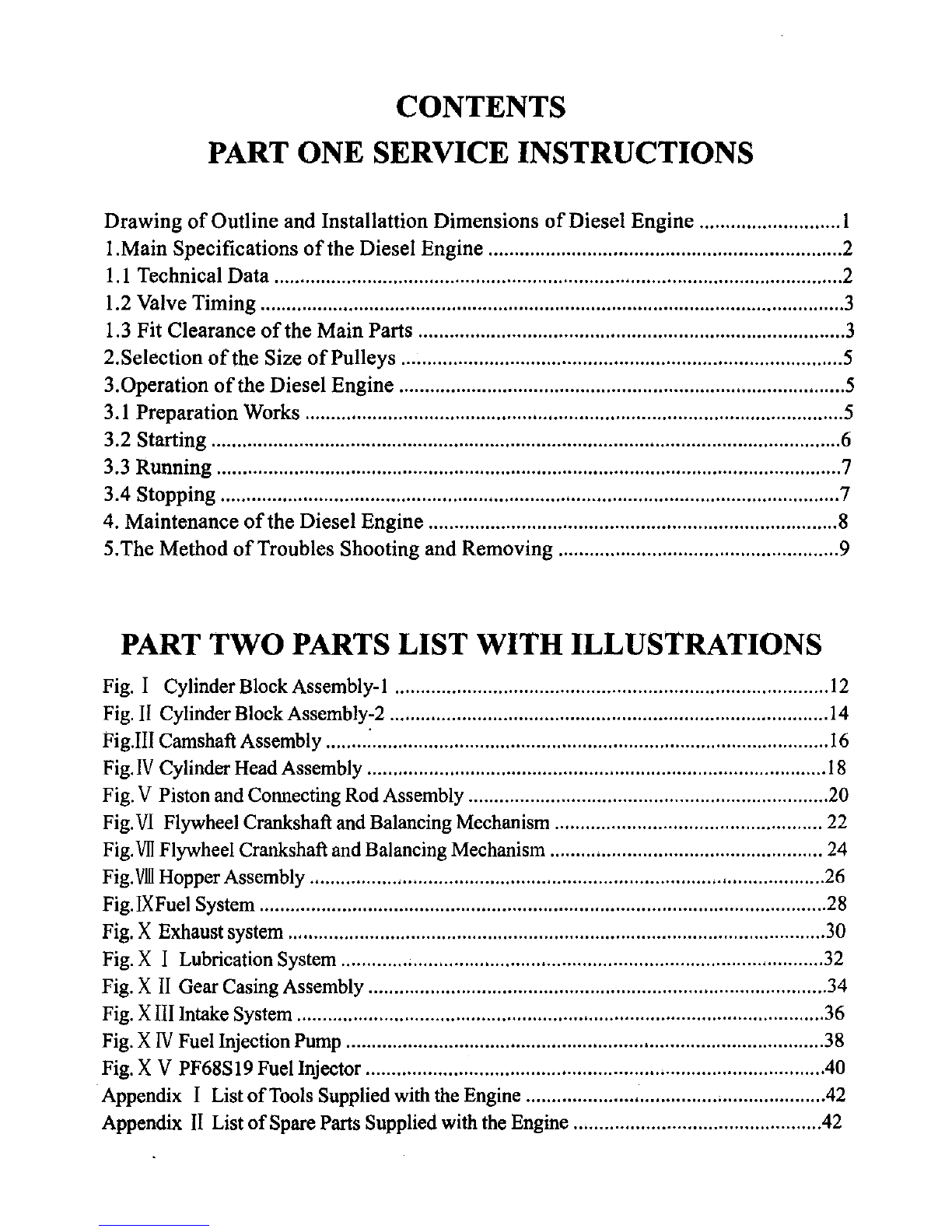
CONTENTS
PART ONE SERVICE INSTRUCTIONS
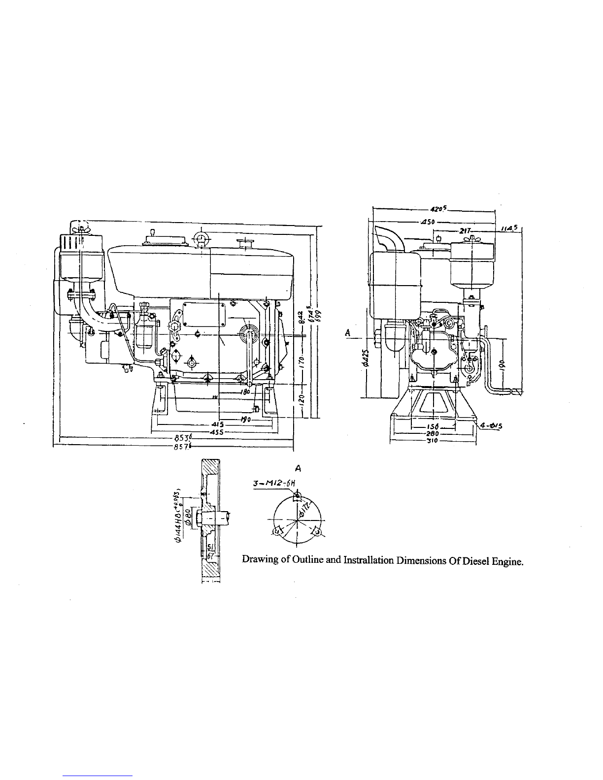
Drawing
of
Outline
and Installattion
Dimensions
of
Diesel
Engine
.1
I.Main
Specifications
of
the Diesel Engine 2
1.1
Technical
Data
2
1.2 Valve Timing 3
1.3
Fit
Clearance
of
the
Main
Parts 3
2.Selection
of
the Size
of
Pulleys 5
3.0peration
of
the Diesel
Engine
5
3.1 Preparation Works 5
3.2 Starting 6
3.3
Running
7
3.4 Stopping 7
4. Maintenance
of
the Diesel Engine 8
5.The
Method
of
Troubles Shooting
and
Removing
9
PART
TWO
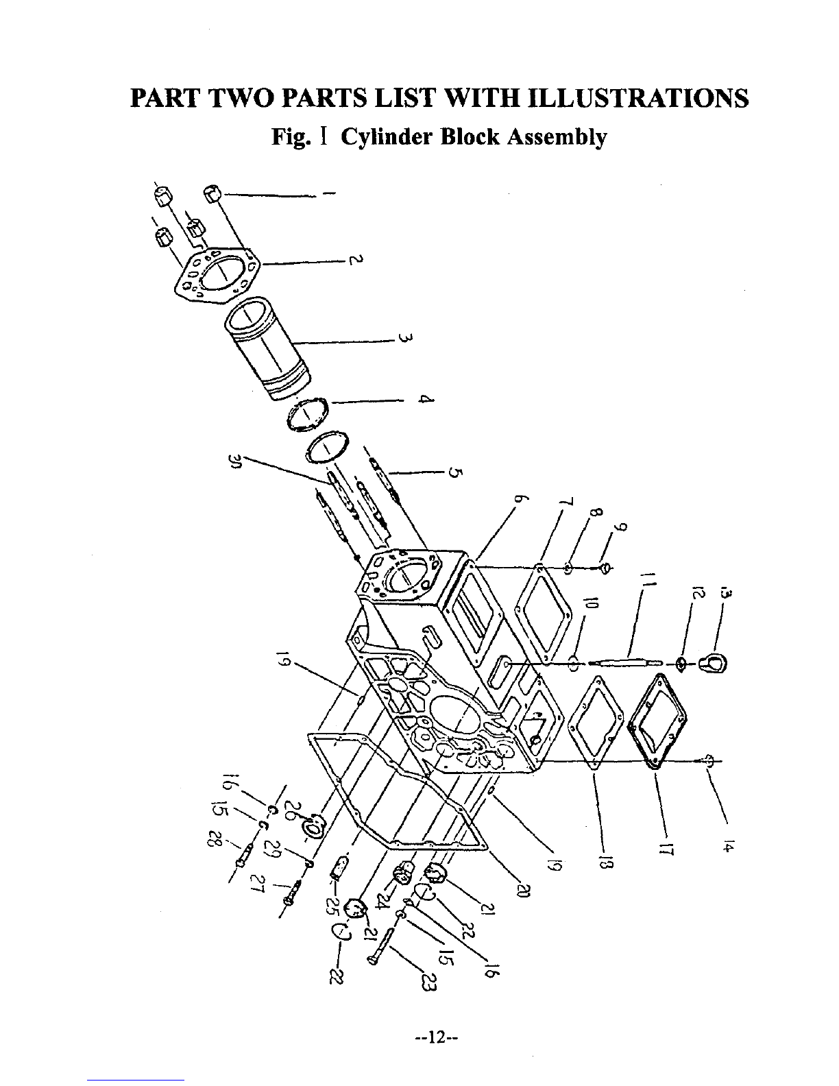
PARTS LIST WITH ILLUSTRATIONS
Fig. ICylinder BlockAssembly-I
12
Fig.
II
Cylinder Block Assembly-2
14
Fig.III CamshaftAssembly :
16
Fig.
IV
Cylinder Head Assembly
18
Fig. VPiston and Connecting Rod Assembly 20
Fig.
VI
Flywheel Crankshaft and Balancing Mechanism
22
Fig.
VII
Flywheel Crankshaft and Balancing Mechanism
24
Fig.
VllI
Hopper Assembly
26
Fig.IXFuel System
28
Fig. XExhaust system 30
Fig. X I Lubrication System ;32
Fig. X
II
Gear Casing Assembly .34
Fig. XIII Intake System 36
Fig. X
IV
Fuel Injection Pump .38
Fig. X V PF68S
19
Fuel Injector .40
Appendix IList
of
Tools Supplied with the Engine .42
Appendix
II
List
of
Spare Parts Supplied with the Engine .42
.
~-~~
II
@1_Kst~~
I
853i6-6
=======11
I
8ni-
s
420,-
'~
'4S0
.In
2'7-
If
AS
D
Po
!--<L
J.
~
"
;::::=
,
,I
~Ji
'»1<'
~
,
"-
'01
lQ
I~
1
~
'T,
"-
A'/
~h-~
0-
jJ
1
;/~/T\'
\
-'56--4
I~S
280
3'10
A
I
~
_IJ
f~
==IF
A
:S-MJ2
c
611
Drawing
of
Outline and Instrallation Dimensions
Of
Diesel Engine.
.,

l.Main
specifications
of
the
Diesel
Engine
1.1 Technical Data
Item Specifications
Model
Zsl115G
Type
single-cylinder,horizontal and
four-stroke circle
Type
of
combustion chamber direct injection
Cylinder bore 115mm
Piston stroke 115mm
Piston displacement 1.195L
Average speed
of
piston 8,44m/s
Compression ratio
17
Rated power 14.7kw/2200r/min
Average effedtive pressure 739.75Kpa
Fuel consumption ratio
~
238g/kw· h
Oil consumption ratio
~
1.47g/kw . h
Injection pressure 18.13 +0,49Mpa(185 +5kgf/cm2)
Cooling style water cool evaporation
Starting style hand cranking
Net weight
~
185kg
Outline dimensions 858 X450 X699
valve gaps (cold state) intake valve 0.35 +0.05mm
exhaust valve 0.45 +0.05mm
Type
of
injector PF68S19
Type
of
injector coupler ZCKI54S432A
Type
of
injector pump AKModle,single-piece and
separable rotor type
Oil pump rotor type rotor type
Diesel oil filter body model C0506C Model
Tightening torque
of
cylinder 274.4-313.6N· M
cover nut
Tightening rorque
of
cnnectingrod 78.4-[ 17.6N . M
nut
Tightening torque
of
flywheel nut 295-350N· M
--2--
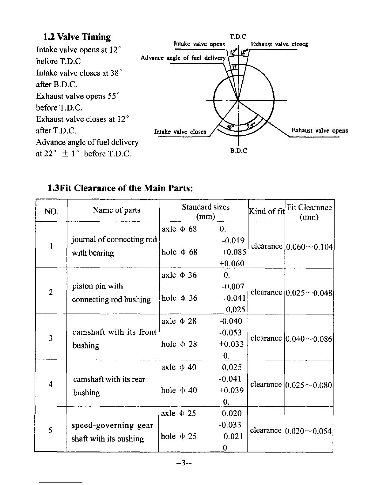
1.2 Valve Timing
Intake valve opens at
12
0
before T.D.C
Intake valve closes at
38
0
after B.D.C.
Exhaust valve opens
55
0
before T.D.C.
Exhaust valve closes at
12
0
after T.D.C.
Advance angle
of
fuel delivery
at 22" +10before T.D.C.
T.D.C
Intake
valve opens
Advance angle
of
fuel delivery \.:=-r:::..,
Intake valve closes
B.D.C
Exhaust valve opens
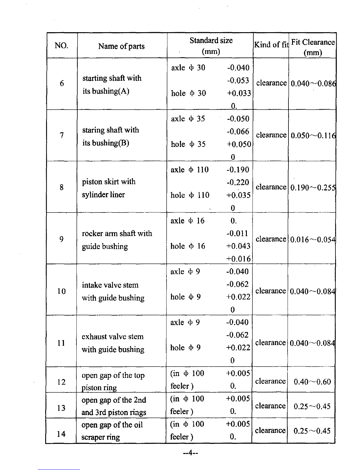
1.3Fit Clearance
of
the Main Parts:
NO.
Name
of
parts Standard sizes Kind
offi
Fit Clearance
(mm) (mm)
axle
<I>
68
O.
1journal
of
connecting rod -0.019 clearance
with bearing hole
<I>
68 +0.085
0.060~0.I
04
+0.060
axle
<I>
36
O.
2piston pin with -0.007 clearance
connecting rod bushing hole
<I>
36 +0.041
0.025~0.048
0.025
axle
<I>
28 -0.040
camshaft with its front -0.053 clearance
3
0.040~0.086
bushing hole
<I>
28 +0.033
O.
-~
axle
<I>
40 -0.025
4camshaft with its rear -0.041 clearance
0.025~0.080
bushing hole
<I>
40 +0.039
O.
axle
<I>
25
-0.020
5
speed-governing
gear
-0.033 clearance
0.020~0.054
shaft with its bushing hole
<I>
25
+0.02I
O.
--3--
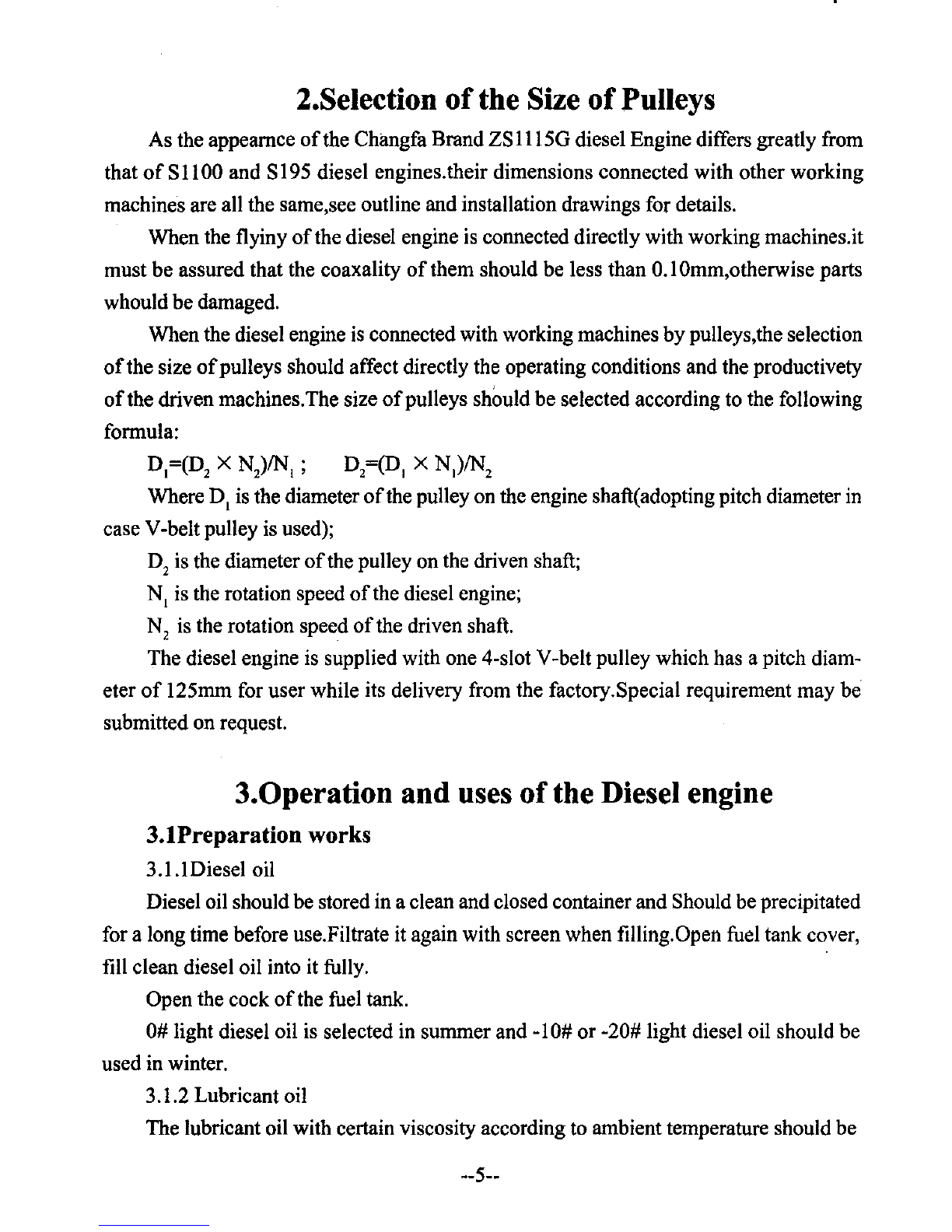
NO. Name
of
parts Standard size Kind
offi
Fit Clearan
(mm) ce
(mm)
axle
<P
30 -0.040
6starting shaft with -0.053
its bushing(A) clearance
0.040~0.0
8<i
hole
<P
30 +0.033
O.
axle
<P
35
-0.050
7staring shaft with -0.066
its bushing(B) hole
<P
35 clearance
0.050~0.11
(
+0.050
0
axle
<P
110 -0.190
8piston skirt with -0.220
sylinder liner hole
<P
110 clearance
0.190~0.25:
+0.035
0
axle
<P
16
O.
9rocker arm shaft with -0.011
guide bushing hole
<P
16
+0.043 clearance
0.016~0.05"
+0.016
axle
<P
9-0.040
10 intake valve stem -0.062
with guide bushing hole
<P
9+0.022 clearance
0.040~0.08~
0
axle
<P
9-0.040
11
exhaust valve stem -0.062
with guide bushing hole
<P
9+0.022 clearance
0.040~0.08~
0
12 open gap
of
the top (in
<P
100 +0.005
piston ring feeler)
O.
clearance
0.40~0.60
13
open gap
of
the 2nd (in
<P
100 +0.005
and 3rd piston riags feeler)
O.
clearance
0.25~0.45
open gap
of
the oil (in
<P
100 +0.005
14
scraper ring clearance
0.25~0.45
feeler)
O.
--4--
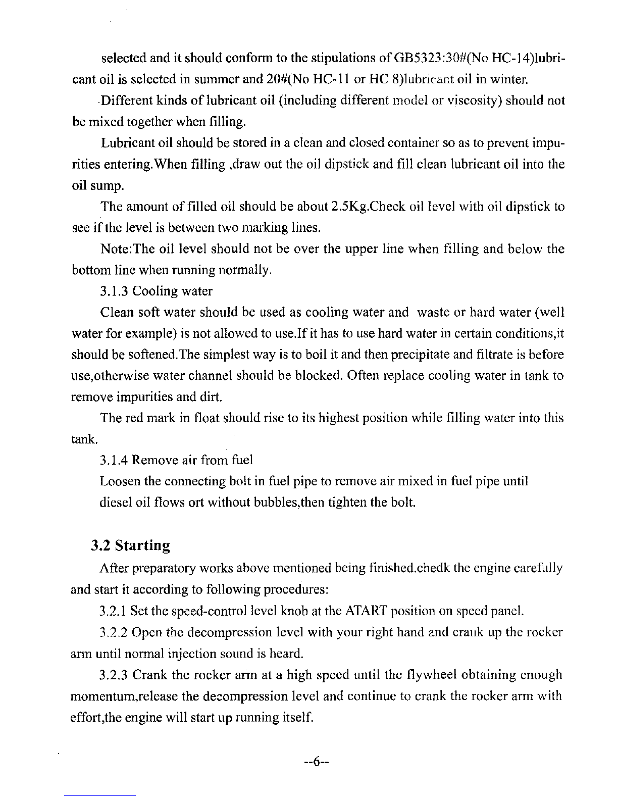
2.Selection
of
the Size
of
Pulleys
As the appearnce
of
the Chilngfa Brand ZS1115G diesel Engine differs greatly from
that
of
S
11
00
and S195 diesel engines.their dimensions connected with other working
machines are all the same,see outline and installation drawings for details.
When the flyiny
of
the diesel engine is connected directly with working machines.it
must
be
assured that the coaxality
of
them should be less than 0.1 Omm,otherwise parts
whould
be
damaged.
When the diesel engine
is
connected with working machines
by
pulleys,the selection
of
the size
of
pulleys should affect directly the operating conditions and the productivety
of
the driven machines.The size
of
pulleys should
be
selected according to the following
formula:
D,=(D2XN2
)1N,
;D2=(D, X
N,)1N
2
Where D, is the diameter
of
the pulley on the engine shaft(adopting pitch diameter in
case V-belt pulley is used);
D2is the diameter
of
the pulley onthe driven shaft;
N, is the rotation speed
of
the diesel engine;
N2is the rotation speed
of
the driven shaft.
The diesel engine is supplied with one 4-slot V-belt pulley which has apitch diam-
eter
of
125mm for user while its delivery from the factory.Special requirement may
be
submitted on request.
3.0peration and uses
of
the Diesel engine
3.1Preparation works
3.1.1Diesel oil
Diesel oil shouldbe stored in aclean and closed containerand Should be precipitated
for along time before use.Filtrate it again with screen when filling.Open fuel tank cover,
fill clean diesel oil into it fully.
Open the cock
of
the fuel tank.
0#
light diesel oil is selected in summer and -10#
or
-20# light diesel oil should be
used in winter.
3.1.2 Lubricant oil
The lubricant oil with certain viscosity according to ambient temperature should be
--5--
selected and it should conform to the stipulations ofGB5323:30#(No HC-14)lubri-
cant oil is selected in summer and 20#(No
HC-II
or HC 8)lubricant oil in winter.
·Different kinds oflubricant oil (including different model or viscosity) should not
be mixed together when filling.
Lubricant oil should be stored in aclean and closed container so
as
to prevent impu-
rities entering.When filling ,draw out the oil dipstick and fill clean lubricant oil into the
oil sump.
The amount
of
filled oil should be about 2.5Kg.Check oil level with oil dipstick
to
see
if
the level is between two marking lines.
Note:The oil level should not be over the upper line when filling and below the
bottom line when running normally.
3.1.3 Cooling water
Clean soft water should be used as cooling water and waste or hard water (well
water for example) is not allowed
to
use.Ifit has
to
use hard water
in
certain conditions,
it
should be softened.The simplest way
is
to
boil
it
and then precipitate and filtrate
is
before
use,otherwise water channel should be blocked. Often replace cooling water
in
tank to
remove impurities and dirt.
The red mark in float should rise
to
its highest position while filling water into this
tank.
3.1.4 Remove air from fuel
Loosen the connecting bolt in fuel pipe
to
remove air mixed in fuel pipe until
diesel oil flows ort without bubbles,then tighten the bolt.
3.2 Starting
After preparatory works above mentioned being finished.chedk the engine carefully
and start it according to following procedures:
3.2.1 Set the speed-control level knob at the
ATART
position on speed panel.
3.2.2 Open the decompression level with your right hand and crallk
up
the rocker
ann
until normal injection sound is heard.
3.2.3 Crank the rocker arm at ahigh speed until the flywheel obtaining enough
momentum,release the
de~ompression
level and continue
to
crank the rocker arm with
effort,the engine will start up running itself.
--6--

3.2.4
Once
the engine starts up running,the staring
handle
will disengage
and
silp
out.
Then
operator
should
keep
it
in
hand
firmly
to
prevent
any
possible
accident.
3.3 Running
3.3.lAfter starting,make the engine running for5-8 minutes at lower speed.then in-
crease speed gradually.The engine runs with full load only when the temperature
of
the
water tank is higher.
3.3.2 Check to see
if
the oil indicator is rising up.The lubrication system is abnormal
if
it does not rise up or drops suddenly,stop the engine at this time and fill lubricant oil
fully or remove troubles.
3.3.3
It
is normal that the cooling water is boiling when the engine is running.
Note:When the mark in float drops down
to
the inlet
of
the water tank,it is necessary
to
till water in time.
3.3.4 Often view the colour
of
exhaust air when the engine is running.!t is not al-
lowed to run the engine when black smoke occurs.This necessary to decrease load or
remove troubles in time.
3.3.5 It
is
not allowed
to
make the engine running with super10ad.Removing the fuel
corrector
to
increase the power
of
the engine is strictly prohibited.
3.3.6 Stop the engine immediately
of
abnormal sound is heard when the engine is
running,the check carethlly.
3.3.7During the period
of
first 50 hours when anew diesel engine is used,operate it
carefully and do not run the engine with the largest10ad,Check again and retighten all
loosened bolts and nuts after that period.
3.4Stopping
3.4.1 Unload the engine and run it at lower speed for awhile.
3.4.2Set
the
throttle
handle
at
the
STOP
position,the
engine
should
go
out
itself.
Note:Stopping the engine with the decompression level is strictly prohibited.
3.4.3Close the cock
of
the fuel tank
--7--
304o4Drain
out
all
cooling
water
in
winter
or
when
stopping
the
engine
for a
long
time.
Remove
drain
cock
regularly
to
dredge
water
channel
and
re-
move
dirt.
304.5Set
the
exhaust
valve
closed
to
prevent
vapour
or
impurities
enter-
ing
into
the
cylinder.The
method
so
as follows:
304.5.1
Turn
the
flywheel
until
it
can
not
be
turned
304.5.20pen
the
decompression
level to
continue
turning
the flywheel until
its
mark
ofT.D.C.is
directly
against
the
mark
on
the
water
tank.
304.6Emergency
stop
Loopen
the
connecting
nuts
on
high-pressure
fuel
pipe
or
open
the
decompress
or
to
stop
the
engine
running
at
once
if
abnormal
sound
is
heard
suddenly
or
flying
running
occurs.
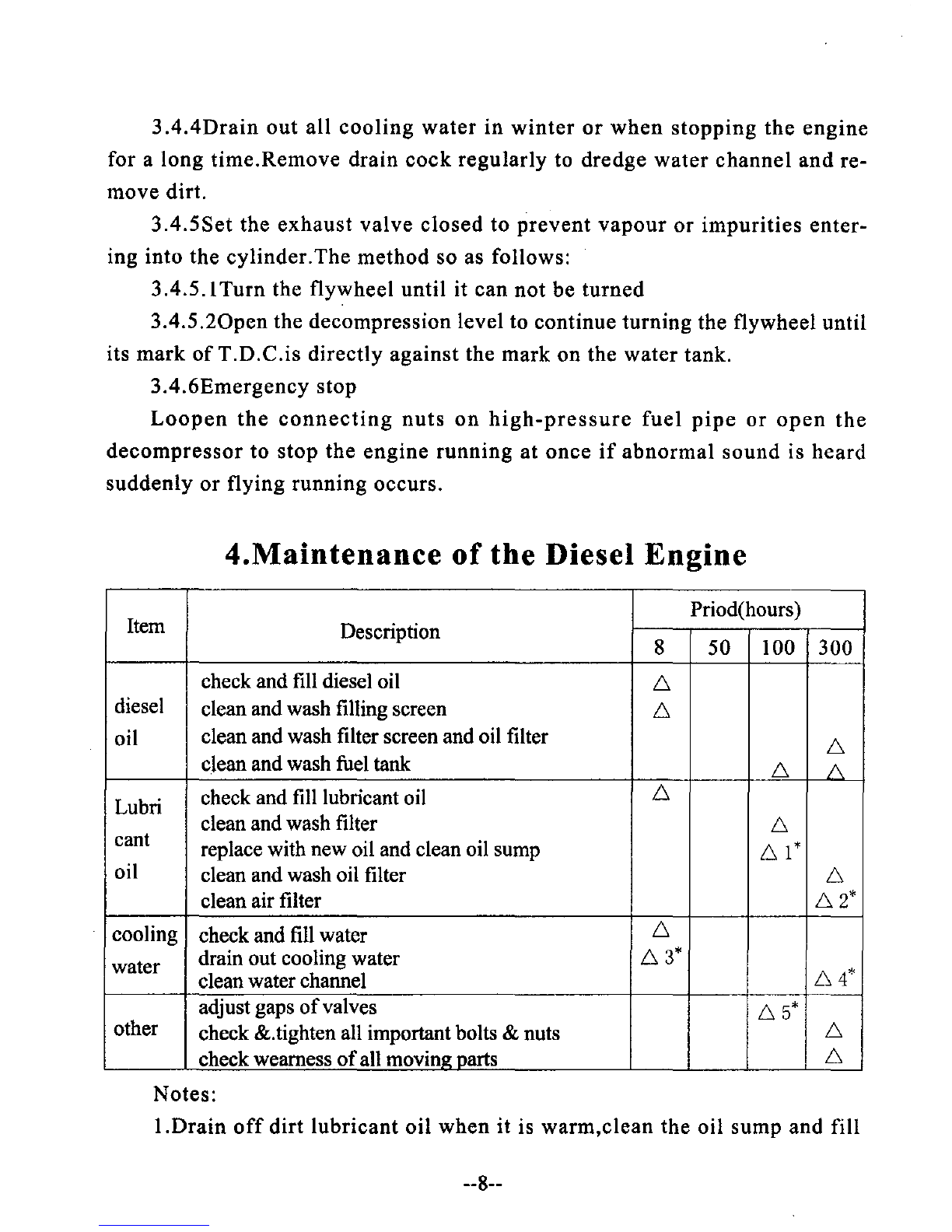
4.Maintenance
of
the
Diesel
Engine
Item Priod(hours)
Description 850 100 300
check and fill diesel oil 6
diesel clean and wash filling screen 6
oil clean and wash filter screen and oil filter 6
clean and wash fuel tank 6
/\
Lubri check and fill lubricant oil 6
clean and wash filter 6
cant replace with new oil and clean oil sump
61*
oil clean and wash oil filter 6
clean air filter
62*
cooling check and fill water 6
water drain out cooling water
63*
clean water channel
64*
adjust gaps
of
valves
65*
other check &.tighten all important bolts &nuts 6
check wearness
of
all
movinl!:
Darts
6
Notes:
I.Drain
off
dirt
lubricant
oil
when
it
is
warm,clean
the
oil
sump
and fill
--8--
new oil.
2.Aircleaner should be cleaned every 50 hours
if
more dust exists around the engine.
3.Drain
off
the cooling water at once after stopping the engine in winter to prevent
engine and cylinder cover being frozen.
4.Remove the watertank and fill hydrochloric acid with adensity
of25
per
cent into
water channel and keep it there for 20 minutes,then drain
off
it and clean channel with
water again and again.
5.Check the gaps
of
valves in cold state every day.It shouldbe 0.3-0.4mm for intake
valve and 0.4-0.5mm for exhaust valve.
5.
The method
of
trouble shooting and removing:
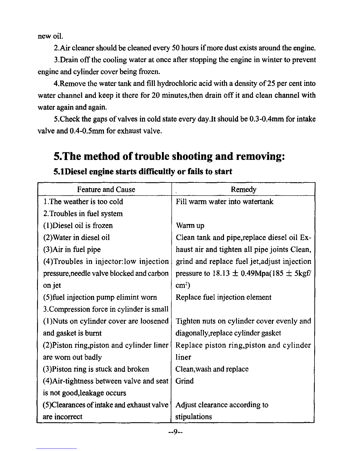
5.1Diesel engine starts difficultly or fails to start
Feature and Cause Remedy
I.The weather is too cold Fill warm water into watertank
2.
Troubles in fuel system
(I
)Diesel oil is frozen Warmup
(2)Water in diesel oil Clean tank and pipe,replace diesel oil Ex-
(3)Air in fuel pipe haust air and tighten all pipe joints Clean,
(4)Troubles in injector:low injection grind and replace fuel jet,adjust injection
pressure,needle valve blockedand carbon pressure to 18.13 +0.49Mpa(185 +5kgf/
on
jet
cm2)
(5)fuel injection pump elimint worn Replace fuel injection element
3.Compression force
in
cylinder
is
small
(I
)Nuts on cylinder cover are loosened Tighten nuts on cylinder cover evenly and
and gasket is burnt diagonally,replace cylindergasket
(2)Piston ring,piston and cylinder liner
Replace
piston
ring,piston
and
cylinder
are worn out badly
liner
(3
)Piston ring is stuck and broken Clean,wash and replace
(4)Air-tightness between valve and seat Grind
is not good,leakage occurs
(5)Clearances
of
intake and exhaust valve Adjust clearance according to
are incorrect stipulations
--9--

5.Viscosity oflubricant oil is thicker,speed
could not be increased
by
hand
Check diesel oil cock,clean oil filter and
fuel pipe
Repair or replace damaged parts
of
pump
Refer to
iteml.2.(
4)of
5
Refer to item1.3.of5
Remove,clean or replace filter
Adjust according to stipulation
Feature and Cause Remedy
:---:-~--t-c::c------:---~-
.-,'-----;--;-:-------
(6)Valve stem is blocked in guide bushing Remove valve,wash valve and guide
(7)Compression ratio is decreased due to bushing with diesel oil
more repairs Replace valve seat
4.Advance angle
of
delivery is incorrect Adjust it at 220+I0before T.D.C.
according to stipulation
Replace lubricant oil with specific brand
5.2 Power is insufficient
Feature and cause Remedy
-----.----.-----.--.-.--f--.-.-----.---=--------
1.Troubles in fuel system
(I
)Diesel oil filter and fuel pipe blocked,
fuel delivery is not smooth
(2)Fuel delivery
of
pump is bad
(3)Troubles in injector
2.Compression force in cylinder is small
3.Air filter clogged
4.Advance angle
offuel
delivery is wrong I
'--
..L...
~
J
5.3 Diesel engine stall
Feature and cause Remedy
..
_---
-----
._---
----.--._.--.----
-_._------1
I.Troubles
in
fuel system
(I)Air in fuel system Remove air
(2)Quality
of
diesel oil
is
bad or there is Refer to item 1.2(2)
of
5
water
in
it
(3)Needle valve
injet
is blocked or injee- Refer to itim 1.2(4)
of
5
tion pressure
is
much higer
(4)Jet coupler,injection pump coupler and Replace damaged parts
fuel out let valve damaged
2.Speed system blocked
or
adjust bolt on Check or adjust the extension
of
bolt
speed level worn out
--10--
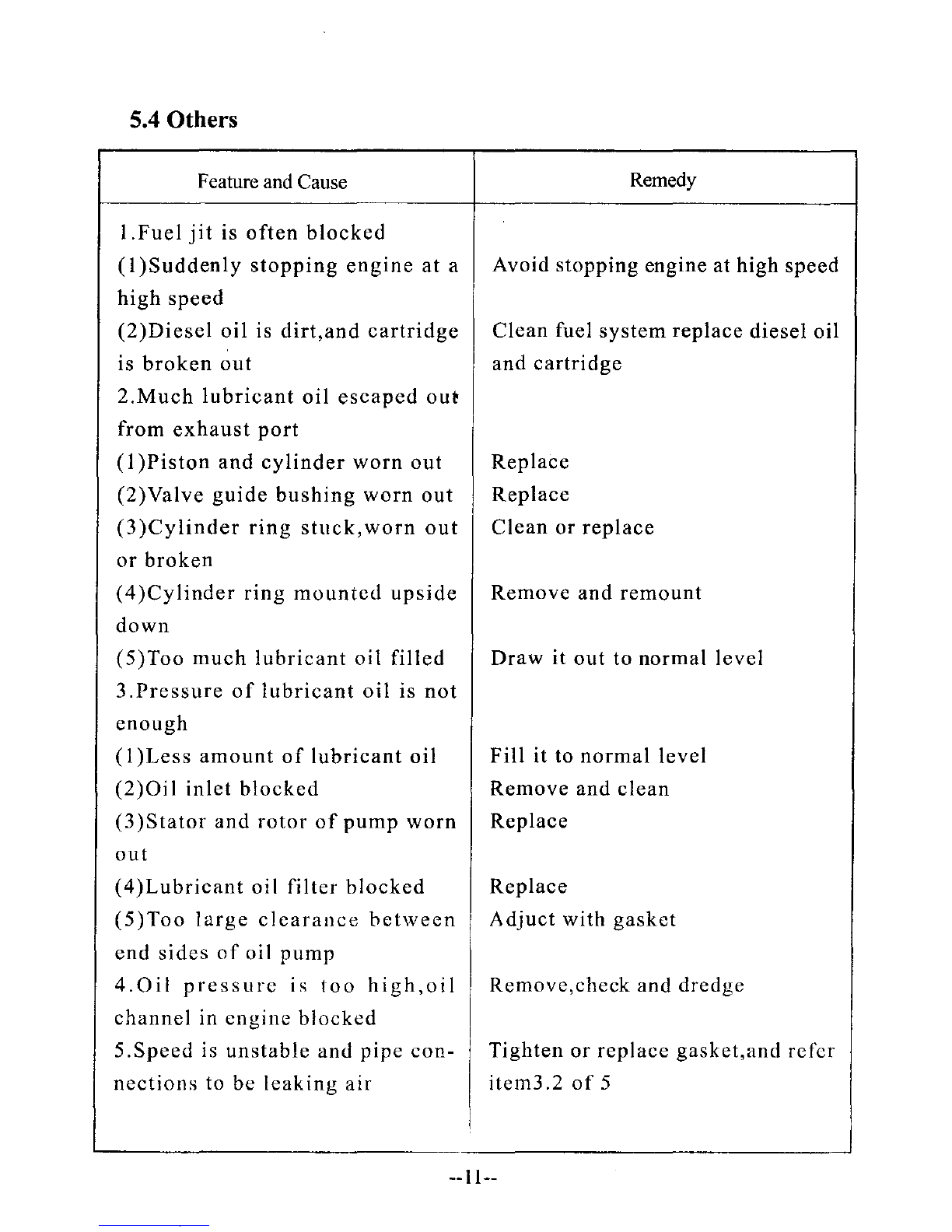
5.4 Others
Feature
and
Cause
Remedy
I.Fuel
jit
is
often
blocked
(I
)Suddenly
stopping
engine
at
aAvoid
stopping
engine at high speed
high
speed
(2)Diesel
oil
is
dirt,
and
cartridge
Clean
fuel
system
replace
diesel
oil
is
broken
out
and
cartridge
2.Much
lubricant
oil
escaped
out
from
exhaust
port
(I
)Piston
and
cylinder
worn
out
Replace
(2)Valve
guide
bushing
worn
out
Replace
(3)Cylinder
ring
stuck,worn
out
Clean
or
replace
or
broken
(4)Cylinder
ring
mounted
upside
Remove
and
remount
down
(5)Too
much
lubricant
oil
filled
Draw
it
out
to
normal
level
3.Pressure
of
lubricant
oil
is
not
enough
(1
)Less
amount
of
lubricant
oil
Fill
it to
normal
level
(2)Oil
inlet
blocked
Remove
and
clean
(3
)Stator
and
rotor
of
pump
worn
Replace
out
(4)Lubricant
oil
filter
blocked
Replace
(5)Too
large
clearance
between
Adjuct
with
gasket
end
sides
of
oi1
pump
4.0il
pressure
is
too
high,oil
Remove,check
and
dredge
channel
in
engine
blocked
5.Speed
is
unstable
and
pipe
con-
Tighten
or
replace
gasket,and
refcr
nections
to be
leaking
air
item3.2
of
5
--11--
PART
TWO
PARTS LIST
WITH
ILLUSTRATIONS
Fig. ICylinder Block Assembly
~_-['l
\----"-"
__
.l'>o
--12--
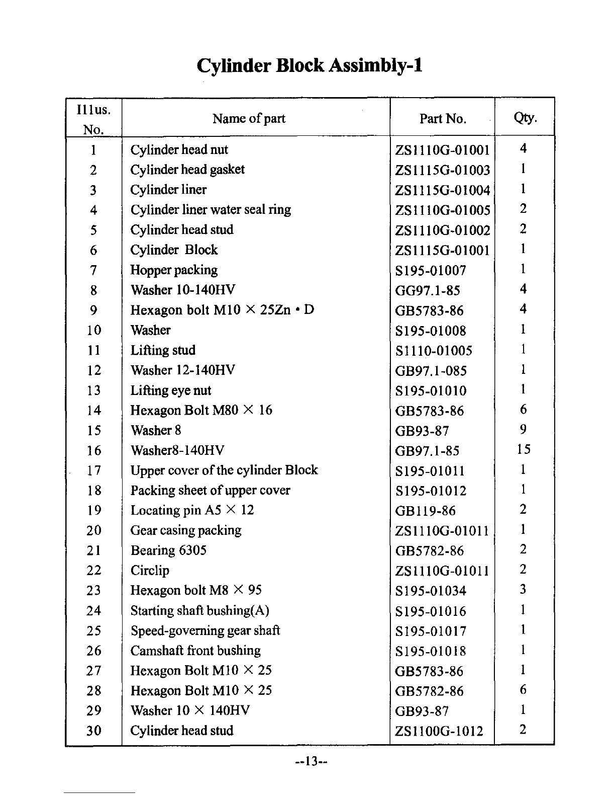
Cylinder BlockAssimbly-l
Illus.
Name
of
part Part No.
Qty.
No.
ICylinderhead nut ZSl1IOG-OIOOI 4
2Cylinder head gasket ZS1115G-01003 I
3Cylinderliner ZSII15G-OI004 I
4Cylinder liner water seal ring ZSIIIOG-OI005 2
5Cylinderhead stud ZS
III
OG-O
I002 2
6Cylinder Block ZS1115G-01001 I
7Hopperpacking S195-01007 I
8Washer 10-140HV GG97.1-85 4
9Hexagon bolt MIO X25Zn • D GB5783-86 4
10 Washer S195-01008 I
11
Lifting stud Sl110-01005 I
12 Washer 12-140HV GB97.1-085 I
13
Lifting eye nut S195-0101O I
14 Hexagon Bolt M80 X
16
GB5783-86 6
15
Washer 8GB93-87 9
16 Washer8-140HV GB97.1-85 15
17 Upper cover
of
the cylinder Block SI95-01011 I
18 Packing sheet
of
upper cover S195-01012 I
19 Locating pin
A5
X
12
GB119-86 2
20 Gear casing packing ZSl1IOG-OI011 I
21
Bearing 6305 GB5782-86 2
22 Circlip ZSl1IOG-OI011 2
23 Hexagon bolt M8 X
95
S195-01034 3
24
Starting shaft bushing(A) S195-01016 I
25 Speed-governing gear shaft S195-01017 I
26 Camshaft front bushing S195-0I0
18
I
27
Hexagon Bolt MIO X
25
GB5783-86 I
28 Hexagon Bolt MI0 X
25
GB5782-86 6
29 Washer
10
X140HV GB93-87 I
30
Cylinderhead stud ZSl1OOG-IOI2 2
--13--

Fig.
11
Cylinder Block Assembly
,•
000
•00
•
__
14--
Cylinder
Block
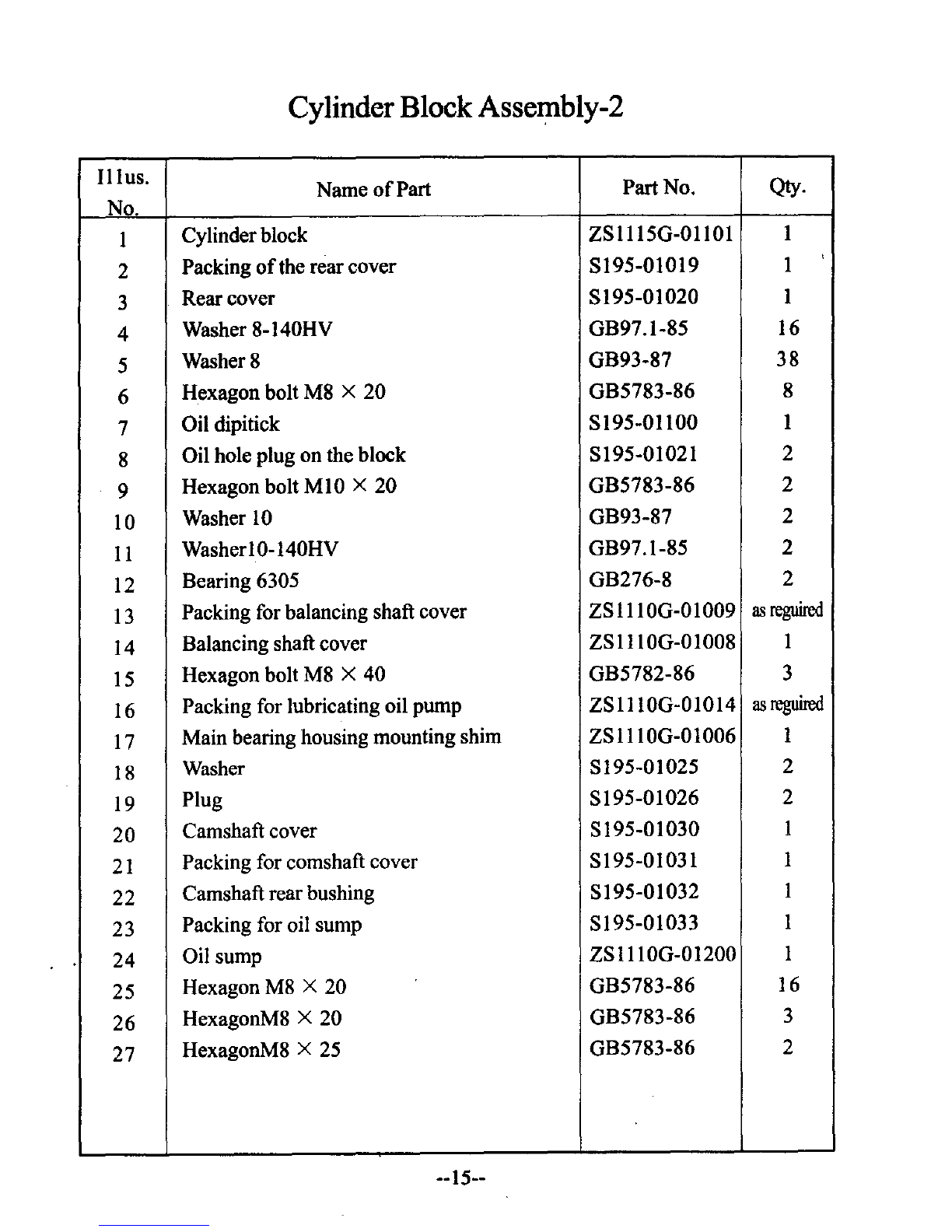
Assembly-2
Hlus.
Name
of
Part Part No. Qty.
No.
ICylinderblock ZS11I5G-01I01 1
2Packing
of
the rear cover S195-01019 I,
3Rear cover S195-01020 I
4Washer 8-140HV GB97.1-85 16
5Washer 8GB93-87
38
6Hexagon bolt M8 X
20
GB5783-86 8
7Oil dipitick
S195-01l00
1
8Oil hole plug on the block S195-01021 2
9Hexagon bolt MIO X
20
GB5783-86 2
10 Washer
IO
GB93-87 2
II
WasherI0-140HV GB97.1-85 2
12 Bearing 6305 GB276-8 2
13
Packing for balancing shaft cover ZS
III
OG-O
I009
as
reguired
14 Balancing shaft cover ZS
III
OG-O
I008 I
15 Hexagon bolt M8 X40 GB5782-86 3
16 Packing for lubricating oil pump ZS
III
OG-O
1014
as
reguired
17 Main bearing housing mounting shim
ZSIIIOG-01006
I
18 Washer 8195-01025 2
19 Plug S195-01026 2
20
Camshaft cover S195-01030 I
21 Packing for comshaft cover 8195-01031 I
22
Camshaft rear bushing S195-01032 I
23 Packing for oil sump 8195-01033 I
24
Oil sump Z81110G-01200 I
25 Hexagon M8 X20 GB5783-86 16
26
HexagonM8 X20 GB5783-86 3
27
HexagonM8 X25 GB5783-86 2
--15--

Fig.
III
Camshaft Assembly
--16--
Table of contents
Other Chang Fa Engine manuals


