7Rev. 1.0
0006152016
TSM34P Hardware Manual
+86 400-820-9661
2.3 Choosing a Power Supply
The main considerations when choosing a power supply are the voltage and current requirements
for the application.
2.3.1 Supply Voltage
The TSM34P is designed to give optimum performance at 48 Volts DC. Choosing the voltage
depends on the performance needed and motor/drive heating that is acceptable and/or does not
cause a drive over-temperature. Higher voltages will give higher speed performance but will cause
the TSM34P to produce higher temperatures. Using power supplies with voltage outputs that are
near the drive’s maximum may signicantly reduce the operational duty-cycle.
The extended range of operation can be as low as 18VDC minimum to as high as 75VDC
maximum. When operating below 18VDC, the power supply input may require larger capacitance
to prevent under-voltage and internal-supply alarms. Current spikes may make supply readings
erratic. The supply input cannot go below 18VDC for reliable operation. Absolute minimum power
supply input is 18VDC. If the input supply drops below 18VDC the low voltage alarm will be
triggered. This will not fault the drive.
Absolute maximum power supply input is 75VDC at which point an over-voltage alarm and fault
will occur. When using a power supply that is regulated and is near the drive maximum voltage
of 75VDC, a voltage clamp may be required to prevent over-voltage when regeneration occurs.
When using an unregulated power supply, make sure the no-load voltage of the supply does not
exceed the drive’s maximum input voltage of 75VDC.
2.3.2 Auxiliary Supply Voltage (Keep Alive Function)
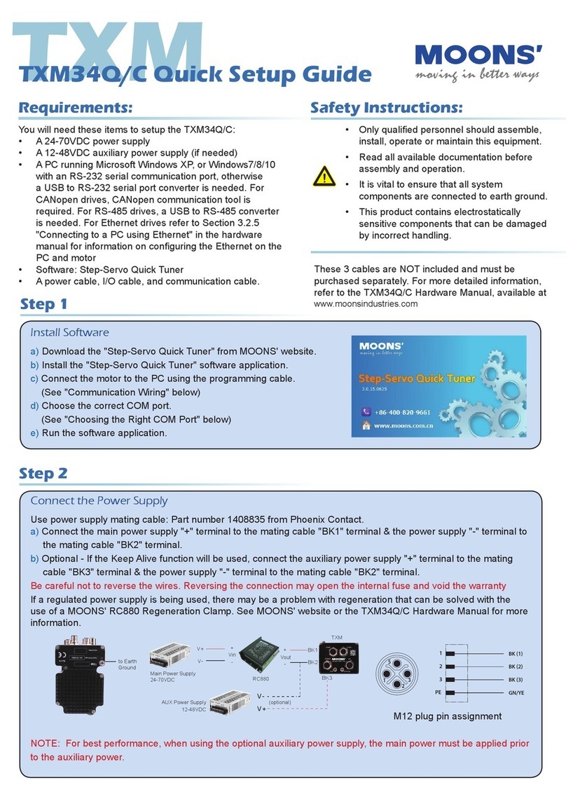
Apart from the main power supply, TSM34 also has an auxiliary power input (AUX power) for
keep alive function of the drive. When the main power supply is off, the AUX power will keep the
logic power on, allowing the drive to remember its state data (motor position, etc.). This allows
the motor to resume operation from its previous position without a homing routine when the main
power is switched back on.
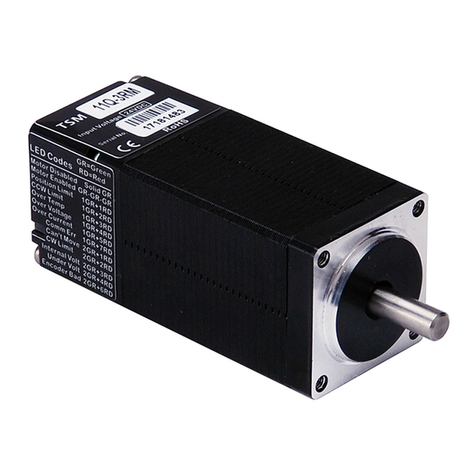
When the main power is removed while the auxiliary power is still on, the drive will show a fault.
If the AUX power supply range is 12-15VDC, the status LED will ash a 3 red, 2 green pattern
indicating the internal voltage is out of range. If the AUX power supply is 15-48VDC, the status
LED will ash a 4 red, 2 green pattern indicating a power supply undervoltage. When the main
power supply is restored the drive will not automatically clear the fault. It will need to be cleared by
the I/O function or SCL commands.
2.3.2.1 Keep Alive Recovery with I/O Function
1. After the main power is removed and the logic remains powered, an undervoltage or internal
bad voltage fault is generated. This alarm will display as a ashing LED pattern which can be
checked by the codes listed in Section 4.1 “Status (STAT) LED Error Codes”.
2. After the main power supply has been restored, the fault must be cleared. Use the alarm reset
function through input 4 (X4) which can be set in the Step-Servo Quick Tuner software. If an
internal bad voltage alarm occurred, the motor will remain disabled. Use the servo on function
through input 3 (X3), also set by the software. If an undervoltage occurred, the motor will reenable
after using the alarm reset function.
3. Resume motion and normal program operation.
2.3.2.2 Keep Alive Recovery with SCL
1. After the main power is removed and the logic remains powered, an undervoltage fault is
