Changzhou Tonghui Electronic TH2638/A User manual

O
OP
PE
ER
RA
AT
TI
IO
ON
N
M
MA
AN
NU
UA
AL
L
TH2638/A
P
P
Pr
r
re
e
ec
c
ci
i
is
s
si
i
io
o
on
n
n
C
C
Ca
a
ap
p
pa
a
ac
c
ci
i
it
t
ta
a
an
n
nc
c
ce
e
e
M
M
Me
e
et
t
te
e
er
r
r
C
C
Ch
h
ha
a
an
n
ng
g
gz
z
zh
h
ho
o
ou
u
u
T
T
To
o
on
n
ng
g
gh
h
hu
u
ui
i
i
E
E
El
l
le
e
ec
c
ct
t
tr
r
ro
o
on
n
ni
i
ic
c
c
C
C
Co
o
o.
..
,
,,
L
L
Lt
t
td
d
d.
..
A
A
Ad
d
dd
d
d:
:
:No.3, Tianshan Road, New District, Changzhou, Jiangsu
T
T
Te
e
el
l
l:
:
:(
(
(0
0
05
5
51
1
19
9
9)
)
)8
8
85
5
51
1
19
9
95
5
55
5
56
6
66
6
6,
,
,8
8
85
5
51
1
13
3
32
2
22
2
22
2
22
2
2
F
F
Fa
a
ax
x
x:
:
:(
(
(0
0
05
5
51
1
19
9
9)
)
)8
8
85
5
51
1
10
0
09
9
99
9
97
7
72
2
2
E
E
E-
-
-m
m
ma
a
ai
i
il
l
l:
:
:
S
S
Sa
a
al
l
le
e
es
s
s@
@
@t
t
to
o
on
n
ng
g
gh
h
hu
u
ui
i
i.
..c
c
co
o
om
m
m.
..c
c
cn
n
n
W
W
We
e
eb
b
bs
s
si
i
it
t
te
e
e:
:
:
h
h
ht
t
tt
t
tp
p
p:
:
:/
/
//
/
/
w
w
ww
w
ww
w
w.
..t
t
to
o
on
n
ng
g
gh
h
hu
u
ui
i
i.
..c
c
co
o
om
m
m.
..c
c
cn
n
n

TH2638/A Operation Manual Ver1.1
II
Contents
Chapter 1 Out of Box Audit..........................................................................................................1
1.1 To Inspect the package.................................................................................................1
1.2 Power connection.........................................................................................................1
1.3 Fuse..............................................................................................................................1
1.4 Environment.................................................................................................................1
1.5 Use of Test Fixture.......................................................................................................2
1.6 Warm-up.......................................................................................................................2
1.7 Other features...............................................................................................................2
Chapter 2 Introduction..................................................................................................................4
2.1 Introduction to front panel ...........................................................................................4
2.2 Introduction to rear panel.............................................................................................7
2.3 FAN..............................................................................................................................8
2.4 Introduction to display zone.........................................................................................8
2.5 Basic Operation..........................................................................................................10
Chapter 3 Basic Measurement Procedure...................................................................................11
3.1 Connecting test fixture...............................................................................................11
3.2 Setting up basic measurement conditions ..................................................................11
3.3 Executing measurement to compensate errors...........................................................15
3.4 Connecting the DUT (capacitor)................................................................................19
Chapter 4 Configuration of Measurement Conditions and Display............................................21
4.1 Selecting a measurement parameter...........................................................................21
4.2 Configuration of measurement signal (frequency and level) .....................................22
4.2.1 Setting frequency .......................................................................................22
4.2.2 Setting level................................................................................................22
4.2.3 Setting signal level compensation (SLC) function.....................................22
4.3 Selecting measurement range.....................................................................................23
4.4 Selecting measurement speed.....................................................................................24
4.5 Configure three-parameter measurement (Cs-Rs-Ls) ................................................24
4.6 Selecting the cable length...........................................................................................25
4.7 Configuration of average factor .................................................................................25
4.8 Configuration of trigger delay time............................................................................26
4.9 Synchronous clock source function............................................................................26
4.10 Configuration of frequency shift................................................................................27
4.11 Configuration of display ............................................................................................27
4.11.1 ON/OFF of display.....................................................................................27
4.11.2 Using fixed display.....................................................................................28
4.11.3 Deviation test mode....................................................................................28
4.12 Configuration of list sweep function..........................................................................29
4.12.1 Sweep modes..............................................................................................29
4.12.2 Sweep parameter........................................................................................30
4.12.3 Sweep Points and Limit Mode ...................................................................30
4.13 Configuration of contact check..................................................................................31

TH2638/A Operation Manual Ver1.1
III
4.14 Configuration of limit table beep...............................................................................32
4.15 BEEPER.....................................................................................................................32
4.16 BEEPER TONE .........................................................................................................33
4.17 LANGUAGE .............................................................................................................33
4.18 PASS WORD .............................................................................................................34
4.19 TALK ONLY..............................................................................................................34
4.20 BAUD RATE .............................................................................................................34
4.21 TIME..........................................................................................................................35
4.22 GPIB ADDR ..............................................................................................................35
4.23 LAN SETUP ..............................................................................................................35
4.24 File Manage................................................................................................................36
4.24.1 Setup file for single-group component.......................................................36
4.24.2 U-disk manage performance ......................................................................37
4.24.3 Operation steps for file management..........................................................38
4.24.4 Saving measurement results into USB memory.........................................39
4.24.5 Saving a Screenshot into USB Memory.....................................................42
Chapter 5 Correction...................................................................................................................43
5.1 Introduction of correction functions...........................................................................43
5.1.1 OPEN/SHORT/LOAD/compensation correction.......................................43
5.1.2 Cable correction.........................................................................................44
5.2 Turning ON/OFF correction function ........................................................................44
5.2.1 Turning on OPEN correction......................................................................44
5.2.2 Turning on SHORT correction...................................................................44
5.2.3 Turning on LOAD correction.....................................................................45
5.2.4 Turning ON OFFSET correction................................................................45
5.3 Obtaining correction Data..........................................................................................46
5.3.1 Obtaining data for OPEN correction..........................................................46
5.3.2 Obtaining data for SHORT correction........................................................46
5.3.3 Obtaining data for LOAD correction .........................................................46
5.3.4 Selecting Single/Multiple Correction Mode...............................................49
5.3.5 Setting data for offset correction................................................................49
5.4 Checking displaying/Setting up correction Data........................................................50
5.4.1 Checking displaying/setting up data for OPEN correction ........................50
5.4.2 Checking displaying/setting up data for SHORT correction......................50
5.4.3 Checking displaying/setting up data for LOAD correction........................50
5.5 Avoiding mistakes related to work in obtaining correction data................................51
Chapter 6 Executing Measurement.............................................................................................52
6.1 Starting (triggering) Measurement.............................................................................52
6.1.1 Setting the trigger mode.............................................................................52
6.1.2 Perform successive measurements automatically ......................................52
6.1.3 Specifying measurement time....................................................................52
6.1.4 Inputting the trigger signal.........................................................................53
6.2 Tips for more accurate measurement .........................................................................53
6.2.1 Setting the measurement time to 8.............................................................53

TH2638/A Operation Manual Ver1.1
IV
6.2.2 Selecting an appropriate measurement range.............................................53
6.2.3 Using correction function...........................................................................54
6.2.4 Improving measurement stability...............................................................54
6.2.5 Using a four-terminal pair in measurement................................................54
6.2.6 Using frequency shift.................................................................................54
6.3 Tips for higher measurement speed............................................................................54
6.3.1 Set the measurement time to 1 ...................................................................54
6.3.2 Setting measurement range mode to the fixed range..................................54
6.3.3 Turning OFF display..................................................................................55
6.3.4 Decreasing the average time ......................................................................55
6.3.5 Setting the trigger delay time to 0..............................................................55
6.3.6 Reducing the waiting time for analog measurement..................................55
6.3.7 Turning off the status register update.........................................................55
Chapter 7 Limit setup (comparator function) .............................................................................56
7.1 Turning ON/OFF Comparator Function.....................................................................56
7.2 Setting up sorting judgment conditions......................................................................56
7.2.1 Clearing (resetting) limit ranges.................................................................56
7.2.2 Selecting a limit range designation method................................................57
7.2.3 Setting up limit ranges................................................................................59
7.2.4 Setting up AUX function............................................................................60
7.3 Judgment of Low Measured Results..........................................................................61
7.3.1 Turning ON/OFF Low C reject function....................................................61
7.3.2 Setting up limit of Low C reject function...................................................61
7.4 Reading out Sorting Judgment Result........................................................................62
7.5 Reading out sorting count of each BIN (BIN count function) ...................................64
7.6 Making a beep for sorting judgment result ................................................................64
Chapter 8 HANDLER Interface .................................................................................................65
8.1 Output of Comparator Sorting Result ........................................................................65
8.2 Input/Output signal pin assignment............................................................................66
8.3 Timing diagram..........................................................................................................69
8.4 List Scan signal line...................................................................................................70
8.5 Electrical Characteristics............................................................................................74
8.5.1 Output Signal .............................................................................................74
8.5.2 Input Signal................................................................................................76
Chapter 9 SCAN Interface..........................................................................................................78
9.1 Use Multi-Channel Correction...................................................................................78
9.1.1 Turn multi-channel correction on/off.........................................................78
9.1.2 Select one channel......................................................................................78
9.1.3 Measuring multiple calibration data...........................................................79
9.2 Input/output pin assignment.......................................................................................81
9.3 Timing Diagram.........................................................................................................82
9.4 Electrical characteristics.............................................................................................83
9.4.1 Output signal..............................................................................................83
9.4.2 Input signal.................................................................................................84

TH2638/A Operation Manual Ver1.1
V
Announcement
The description of the manual may not cover all contents of the instrument, and our company is
subject to change and to improve the performance, function, inner structure, appearance, accessory
and package of the instrument without notice. If there is puzzle caused by inconsistency of manual
and instrument, then you can contact with our company by the address on the cover.

1
Chapter 1 Out of Box Audit
When you receive the instrument, some inspections are necessary, and the condition must be
understood and available before installing the instrument.
1.1 To Inspect the package
Inspect the shipping container for damage after unpacking it. It is not recommended to power
on the instrument in the case of a damaged container.
If the contents in the container do not conform to the packing list, notify us or your dealer.
1.2 Power connection
1) Power-supplying voltage range: 100-120Vac or 198~242Vac.
2) Power-supplying frequency range: 47~63Hz.
3) Power-supplying power range: not less than 200VA.
4) Power supplying input phase line L, zero line N, ground lead E should be as same as the
power plug of the instrument.
5) After careful design, the instrument can reduce the clutter jamming caused by AC power
terminal input; however, it should be used under the environment with low-noise. Please
install power filter if being unavoidable.
Warning: In order to prevent user and instrument from being hurt by leakage, it is necessary
for user to guarantee the ground line of supply power being reliably grounded.
1.3 Fuse
The instrument has installed fuse, so operators should use the installed fuse of our company.
—————————————————————————————————————
Warning: Be sure that the location of fuse is consistent with power-supplying voltage
range before charging.
———————————————————————————————————————
1.4 Environment
1) Please do not operate the instrument in the place that is vibrative, dusty, under direct
sunlight or where there is corrosive air.
2) The normal working temperature is 0℃~40℃, relative humidity ≤75%, so the instrument
should be used under above condition to guarantee the accuracy.
3) There is heat abstractor on the rear panel to avoid the inner temperature rising. In order to

2
keep good airiness, please don’t obstruct the left and right airiness holes to make the
instrument maintain the accuracy.
4) Although the instrument has been specially designed for reducing the noise caused by ac
power, a place with low noise is still recommended. If this cannot be arranged, please
make sure to use power filter for the instrument.
5) Please store the instrument in the place where temperature is between 5℃and 40℃,
humidity is less than 85%RH. If the instrument will not be put in use for a time, please
have it properly packed with its original box or a similar box for storing.
6) The instrument, especially the test cable should be far from strong electro-magnetic field,
to avoid the jamming on measurement.
1.5 Use of Test Fixture
Please use the accessory test fixture or cable, the test fixture made by user or from other
company may cause the incorrect measurement result. The test fixture or cable should be
kept clean, as well as the pin of DUT, thus to guarantee the good connection between DUT and
fixture.
Connect the fixture or cable to four test terminals Hcur, Hpot, Lcur, Lpot on the front panel. As
for the DUT with shielding shell, connect shielding layer or ground “┴”.
Note: When test fixture or cable has not being installed, the instrument will display an unstable
test result.
1.6 Warm-up
1) To guarantee the accurate measurement, the warm-up time is no less than 15min.
2) Please not turn on or off instrument frequently, in order to avoid the inner data fluster.
1.7 Other features
1) Power: consumption power≤150VA.
2) Dimension (W*H*D): 369mm*108mm*408mm;
3) Weight: About 5 kg.
4
Chapter 2 Introduction
In this chapter, the basic operation procedures and names & functions of the front panel, rear
panel as well as screen display of TH2638 are described.
Product Introduction
TH2638 is a capacitance meter for ceramic capacitor production tests. It can be used for
evaluating ceramic capacitance at frequencies 100Hz, 120Hz, 1kH, 10 kHz, 40 kHz, 100 kHz, 1
MHz and test signal levels (0.1 V to 1 V).
TH2638 offers C-D measurement with a basic accuracy of ±0.07% (C), ±0.0005 (D) at all
frequencies with seven-digit resolution (the dissipation factor resolution is 1 ppm) in every
range.
With its built-in comparator, TH2638 can output comparison/decision results for sorting
components into a maximum of ten bins. Furthermore, by using the handler interface and
scanner interface, TH2638 can be easily combined with a component handler, a scanner, and
a system controller to fully automate component testing, sorting and quality-control data
processing.
The GPIB/LAN/USB interfaces are standard on the TH2638 (no GPIB and Scanner interface in
TH2638A) and enable automatic testing.
2.1 Introduction to front panel
Figure 2-1 shows the front panel of TH2638.
POWER
CATⅠ
MEAS SETUP SYSTEM
SYNC CLK LCUR LPOT HPOT HCUR
UNKNOWN
COPY 7PQRS 98 TUV WXYZ
6
5
4GHI JKL MNO
321 ABC DEF ENTER
ESC
+/-
0
RESET
KEYLOCK
PRESET
FORMAT
DISPLAY
PASS FAIL
TRIGGER
TH2638 Capacitance Meter 100Hz-1MHz
!
±10V Peak Max
!
±5V Peak Max
LOG
1
21 20
6 9
15 14
24
19
25
12
2
17 16
710
23
11
8
13
3 4 5
18
22
Figure 2-1 Front panel

5
1) Brand and model
Brand and model.
2) [COPY]
Press this key to save the screen shot of test result to USB disk.
3) [MEAS]
Press this key to enter into the measurement result display page.
4) [SETUP]
Press this key to set the measurement conditions, limit values of correction, list setup, file
setup and contact check function.
5) [SYSTEM]
Set the system. Set the GPIB/LAN interface. Default setting and system reset.
6) Numerical keys
These keys are used to input data to the instrument. The key consists of numerical keys [0]
to [9], decimal point [.] and [+/-] key. Entered values are displayed on the input line
(second line from the bottom of the LCD screen), and pressing the softkey terminates
numeric input. The plus/minus key deletes the last character of the input value.
7) [ESC]
ESCAPE key.
8) [←]
BACKSPACE key. Press this key to delete the last number input.
9) PASS indicator
PASS LED indicator shows the test result has passed.
10) FAIL indicator
FAIL LED indicator shows the test result has failed.
11) [RESET]
Press this key to stop scanning only in transformer automatic scanning. No operation will
be executed on other pages.
12) [TRIGGER]
When the trigger mode is set to MAN mode, press this key to trigger the instrument.
13) [ENTER]
Stop data inputting, confirm and save the data displayed in the input line (the bottom line
on the LCD).

6
14) UNKNOWN terminals
These are the UNKNOWN terminals used to connect a four-terminal pair test fixture or
test leads for measuring the device under test (DUT).
NOTE: When using a four-terminal pair test fixture or test leads with a stopper, remove
the stopper or the bumper of TH2638.
Caution: please do not apply DC voltage or current to the UNKNOWN terminals.
Applying DC voltage or current may lead to device failure. Connect the measurement
sample (DUT) to the test port (or the test fixture, cables, etc. connected to the test port)
after the Capacitance meter has been completely discharged.
The maximum load the UNKNOWN terminals can withstand is 10 kgf (rated value).
15) Ground terminal
It is connected to the chassis of TH2638 and used to protect or shield ground connection.
16) Cursor keys
Cursor keys are used to move the field select cursor from field to field on a displayed page.
When the cursor is moved to a certain field, the field will change to an inverse video image
of the original field. The cursor can only be moved from field to field.
17) Synchronous clock
The internal clock signal is outputted.
18) Soft keys
Five soft keys are used to select measurement condition and parameter function. The
corresponding function of each soft key has been displayed in the left.
19) [LOG]
Press this key to save the test data automatically after inserting the U-disk in MEAS
interface and save the system setup in [SYSTEM].
20) LCD
800*480 colorful TFT LCD displays measurement results and conditions.
NOTE: there are missing pixels or constantly lit pixels occasionally, but this is not a
malfunction and does not affect the performance of your product.
21) POWER
Power switch.
22) Display format
Press this key to switch the window or full screen display method of measurement results.
23) Reset
This key is used to return the Capacitance meter to the initial setup state. There are three
methods for initialization.

7
24) [KEYLOCK]
Press [KEYLOCK], it will be lighted, which means the function of current panel is locked.
Press it again, it will be off, which means discharging the lock status. If the password
function is ON, it means correct password is necessary when discharging the key-lock, or
the key cannot be unlocked.
When the instrument is controlled by RS232, [KEYLOCK] will be lighted. Press
[KEYLOCK] again, it will be off, which means returning to the local discharging lock
status.
25) Front USB HOST interface
Connect U flash disk so as to save or load the file.
NOTE: do not unplug the USB disk while in the process of storage.
2.2 Introduction to rear panel
Figure 2-2 shows the rear panel of TH2638.
贴标签
RS-232C
DEVICE
HANDLER
LAN
RATING FUSE
110V/60Hz 80VA
220V/50Hz 80VA T2AL 250V
~
~
T4AL 250V
GPIB SCANNER
TRIGGER
!
TO AVOID ELECTRIC SHOCK,
THE POWER CORD PROTECTIVE GROUNDING CONDUCTOR
MUST BE CONNECTED TO GROUND.
DISCONNECT POWER SUPPLY BEFORE REPLACING FUSE.
WARNING
1 2 3 4 5
9 8 710
6
Figure 2-2 Rear panel
1) LAN interface
The port can connect the TH2638 to a LAN (Local Area Network). Connecting this
instrument to a LAN enables you to control this instrument by using SICL-LAN or telnet,
or from an external PC via a Web server.
2) USB(USBTMC, USBCDC) DEVICE interface
The tester can communicate with PC through the USB DEVICE interface.
3) RS232C interface
Series communication interface can realize the communication with PC.
4) HANDLER interface
This interface is for data exchange with an automatic machine (handler) used on a
production line.

8
5) GPIB interface
General Purpose Interface Bus (GPIB). The connection of an external controller and other
devices through this connector allows you to configure an automatic measurement system.
6) Scanner interface
The interface to connect a scanner can perform up to 256 sets of multi-channel
corrections and measurements.
7) Ground terminal
The ground terminal is connected with instrument casing, being available for protecting or
shielding ground connection.
8) Power socket (to LINE)
Input AC power.
NOTE: To connect the device to a power source (outlet), use the supplied three-prong
power cable with a ground conductor
The plug attached to the power cable (on the power outlet side or device side of the cable)
serves as the disconnecting device (device that cuts off the power supply). When the power
supply must be cut off to avoid such danger as electric shock, pull out the power cable plug
(on the power outlet side or device side of the cable).
9) External trigger input connector
The BNC connector to input the positive/negative TTL pulse can trigger the TH2638 with
external trigger signals. (The trigger mode must be set to EXT).
10) Nameplate
Information about production date, instrument number and manufacturer etc..
2.3 FAN
The cooling fan is used for controlling the temperature inside TH2638. This fan extracts heated
air from inside the Capacitance meter.
2.4 Introduction to display zone
This section describes the names and functions of parts on the LCD screen.

9
Figure 2-3 display zones
1) Display page name
Indicate the name of the currently displayed page.
2) Soft keys
The zone is used to display the function definition of soft key.
A displayed to the right of a softkey indicates that pressing ↓ will display the softkey
label one level lower. Pressing the ← key when the lower level softkey label is
displayed will display the softkey label one level higher.
3) Test condition display zone
In this zone, test condition is displayed.
4) Test result display zone
In this zone, test result information is displayed.
5) System message display zone
In this zone, the system message, warning, and an error message will be displayed.
6) Status display zone
When the front panel key is locked, “LOCK” is displayed in this area. When sending
SCPI commands from an external controller, “RMT” is displayed and the front panel keys
are locked. When TH2638 accesses the USB memory, “USB” is displayed in this area.

10
2.5 Basic Operation
Basic operation of TH2638 is as follows:
Use [MEAS] keys and soft keys to select the desired page.
Use cursor keys ([←][→] [↑] [↓]) to move the cursor to the desired zone. When the cursor
moves to a specified zone, the zone will become reverse expression.
The soft key functions corresponding to the current zone of the cursor will be displayed in
the soft key zone. Users can select and use the desired key. Numeric keys, [←] and
[ENTER] are used to input data.
When a numeric key is pressed down, the usable unit soft key will be displayed in the soft
key zone. You can press [ENTER] to end data inputting.
The unit changes according to the field selected.

11
Chapter 3 Basic Measurement Procedure
This chapter describes the procedure to measure a capacitor with the test fixture by using
TH2638.
3.1 Connecting test fixture
Generally, it is difficult to connect the DUT (capacitor) directly to the TH2638. Therefore, a test
fixture is generally used to connect the DUT to the TH2638. Choose the suitable test fixture for
DUT.
NOTE: To avoid failure, do not apply DC voltage or current to the UNKNOWN terminal.
Special care must be taken for capacitors because they may be charged. Fully discharge before
connecting them to the UNKNOWN terminal (or the test fixture).
3.2 Setting up basic measurement conditions
This section describes how to set up basic measurement conditions for capacitor measurement.
Initializing the Instrument
Step 1: Press [Preset] key.
Step 2: Use the softkeys to select one of the following four default states:
Default state
Initialize the instrument
CLEAR
SETTING
When you select this state, all basic parameters configured
through the front panel and SCPI commands are cleared.
(You get the same result by issuing the :SYST:PRES
command).
CLEAR
SET&CORR
When you select this state, calibration data listed in the initial
setting list are all cleared. (You can get the same result by
issuing the *RST command).
LAN RESET
When you select this state, the LAN setting is returned to the
factory default state.
FACTORY
DEFAULT
When you select this state, it reverts to factory default settings
with all user-configurable data cleared.
NOTE: It takes a few seconds for the initialization to complete.
Setting up measurement parameters
Set up the primary parameter and secondary parameter you want to measure. TH2638 provides
you the following parameter combinations.

12
Primary parameter
Secondary parameter
Cp
D, Q, G, Rp
Cs
D, Q, Rs, Rs –Ls
Each parameter is described below.
Cp: Capacitance value measured by parallel equivalent circuit model
Cs: Capacitance value measured by series equivalent circuit model
D: Dissipation factor
Q: Quality factor (inverse of D)
G: Equivalent parallel conductance measured by parallel equivalent circuit model
Rp: Equivalent parallel resistance measured by parallel equivalent circuit model
Rs: Equivalent series resistance measured by series equivalent circuit model
Rs –Ls:Equivalent series resistance and equivalent series capacitance measured by series
equivalent circuit model
The procedure to set up the measurement parameters is described below.
Step 1: Press the [MEAS] key.
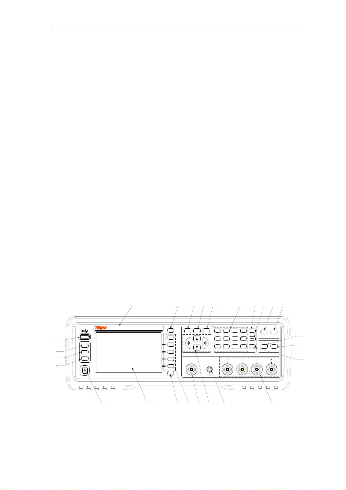
Step 2: Move the cursor key to the FUNC zone (as shown in Figure 3-1).
Step 3: Press the Cp or Cs softkey to select the primary parameter.
13
Figure 3-1 Primary parameter selection menu screen
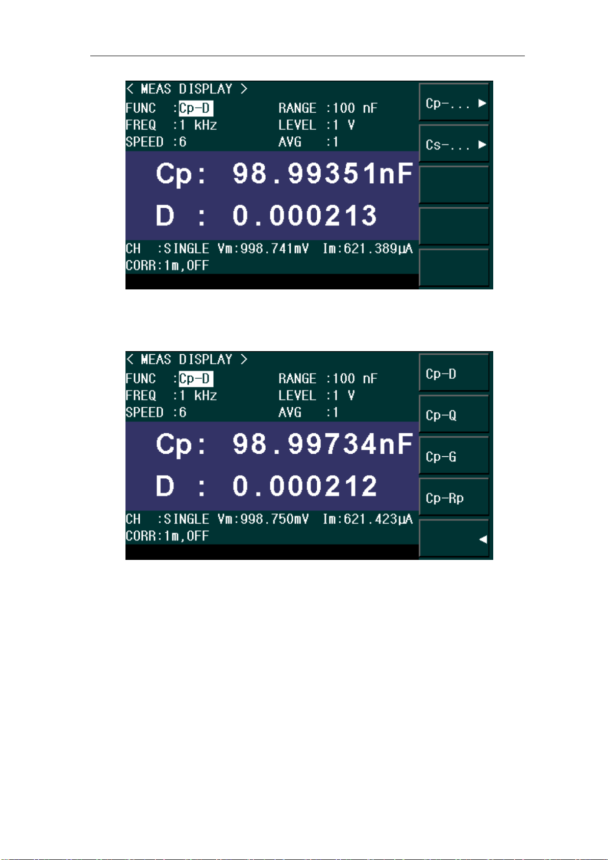
Step 4: Press the softkey to select the secondary parameter (as shown in Figure 3-2)
Figure 3-2 Secondary parameter selection menu screen
Setting up measurement signal frequency
Set up the frequency of the signal applied to the DUT (capacitor) during measurement.
Step 1: Press [MEAS] key.
Step 2: Move the cursor key to FREQ zone.
Step 3: Use the softkeys or entry keys to enter the frequency. When data is entered with the
numeric entry keys, the softkeys change to unit labels (Hz, kHz, MHz).

14
Figure 3-3 Measurement signal frequency selection menu screen
Setting up measurement signal level
Set up the voltage level of the signal applied to the DUT (capacitor) during measurement.
Step 1: Press [MEAS] key.
Step 2: Move the cursor key to the LEVEL zone.
Step 3: Use the softkeys or entry keys to enter the test signal level. When data is entered
with the entry keys, the softkeys change to units labels (mV, V).
Softkey
Description
INCR++
Increments the level in steps of 100 mV, 500 mV, 1 V.
INCR+
Increases the level with a resolution of 10 mV.
DECR-
Decreases the level with a resolution of 10 mV.
DECR--
Decrements the level in steps of 1 V, 500 mV, 100 mV.
Figure 3-4 Measurement signal level selection menu screen

15
Setting up cable length
Select the length of the measurement cable from 0 m, 1 m, or 2 m, depending on the test set
lead you use.
0 m when you do not use the test lead (in other words, when you connect the test
fixture directly to the UNKNOWN terminal).
1m / 2m when you use the test lead to connect the test terminal.
1A when you use Agilent's 1m test cable
The procedure used to set up the length of the measurement cable is described below.
Step 1: Press [SETUP] key.
Step 2: Press the CORRECTION softkey.
Step 3: Move the cursor keys to the CABLE zone.
Step 4: Use the following softkeys:
Softkeys
Description
0m
Sets the cable length to 0 meter.
1m
Sets the cable length to 1 meter.
2m
Sets the cable length to 2 meter.
Figure 3-5 Cable length selection menu screen
3.3 Executing measurement to compensate errors
You can compensate for errors in the measurement caused by disturbances such as stray
admittance and residual impedance of the test fixture and cable.
Corrections should be performed before actually connecting the DUT to the test fixture.
Measuring data for OPEN correction
The OPEN correction is provided to remove stray admittance parallel to the DUT.
Steps for OPEN correction is described as below:
Step 1: Press the [SETUP] key.
16
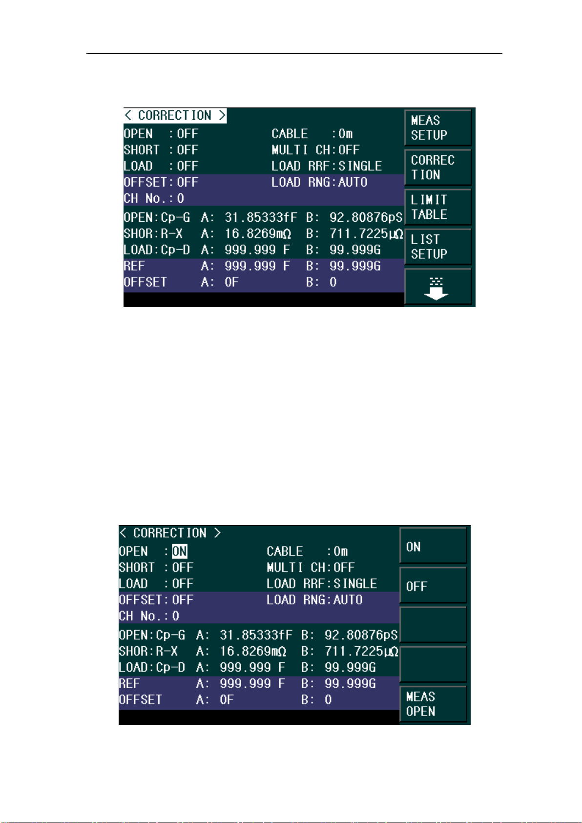
Step 2: Press the CORRECTION softkey. The CORRECTION display page as shown in
Figure 3-6 appears.
Figure 3-6 Correction Screen
Step 3: Use the cursor keys to select the OPEN field.
Step 4: Connect the UNKNOWN terminal and the test fixture with no DUT connected.
Step 5: Press the MEAS OPEN softkey. The data for the OPEN correction is then measured.
During the measurement, an “OPEN measurement in progress” message is shown on the
display.
When the measurement has finished, the “OPEN measurement in progress” message
disappears.
During the measurement, the ABORT softkey is shown. Use this key when you want to abort
open correction.
Step 6: When measurement of the data for OPEN correction is successfully completed, the
OPEN correction turns to ON (as shown in Figure 3-7).
Figure 3-7 Screen upon completion of measuring data for OPEN correction
Table of contents
Other Changzhou Tonghui Electronic Measuring Instrument manuals


