Chapman TF350 User manual


Page 2
Contents
Introduction ......................................................................................................................................3
HSE Information.........................................................................................................................4
Important Safety Information...........................................................................................................8
Safety Information........................................................................................................................8
Transportation Safety ...................................................................................................................9
Operating Safety...........................................................................................................................9
Description......................................................................................................................................10
Identification...............................................................................................................................10
Specification...............................................................................................................................10
Implement Decals.......................................................................................................................12
Attachment......................................................................................................................................13
Before Attaching the Machine....................................................................................................13
Attaching the Machine................................................................................................................13
Drop Size Adjustment & Calibration .............................................................................................14
Spring Change / Replacement ........................................................................................................15
Sensor Change / Adjustment ..........................................................................................................17
Control Box ....................................................................................................................................20
2 Button Model (UNTIL October 2015) ....................................................................................20
4 Button Model (FROM October 2015).....................................................................................21
Operating Limits & Recommendations..........................................................................................23
Forward Speed............................................................................................................................23
Storage........................................................................................................................................23
Troubleshooting..............................................................................................................................24
Warranty.........................................................................................................................................25
The Chapman Warranty..............................................................................................................25
Warranty Conditions...................................................................................................................25
Transfer of Warranty..................................................................................................................26

Page 3
Introduction
By purchasing a Chapman Machinery Ltd TF Series Trailed Feeder you have purchased a product de-
signed to give a long and trouble free service life.
A variety of options are available from the factory, and many of these are also suitable for retro-fitment if
your requirements change, or you purchase this machine used, and wish to use a different set-up. We are
more than happy to offer advice & support throughout the lifetime of the machine.
This manual also contains important Health & Safety Executive information and guidelines.
NOTICE:
THIS MANUAL MUST BE HANDED TO THE OPERATOR BEFORE USE. THE OPERATOR MUST
UNDERSTAND FULLY THE CONTENT OF THIS HANDBOOK BEFORE USING THE MACHINE
FOR THE FIRST TIME. OF THE IMPLEMENT IS RESOLD, THIS MANUAL MUST ACCOMPANY
THE MACHINE.
Note:
The information contained in this manual is correct at the time of going to press. However, in the course of
development, changes in specification are inevitable. Should you find the information given differs from
your machine, please contact Chapman Machinery Ltd direct for advice.
Chapman Machinery Ltd
Hele Barton
Week St.
Mary
Holsworthy
Devon
EX22 6XR
Tel:01288 308149

Page 4
HSE information sheet
Safe use of all-terrain vehicles (ATVs)
in agriculture and forestry
HSE Information
Agriculture Information Sheet No 33
Introduction
This information sheet gives advice on the safe use of
ATVs. It covers the two main types used in off-road
working in agriculture and forestry, which are:
●
sit-astride ATVs: any motorised vehicle designed
to travel on four low-pressure tyres on unpaved
surfaces, with a seat designed to be straddled by
the operator and handlebars for steering control.
They are intended to be used by a single operator
with no passenger. However, this type also
includes ATVsintended for use by a single
operator, but with a special seat for a passenger
behind the operator. These vehicles are generally
called ATVsin agriculture, quad bikes in leisure
use and all-terrain cycles (ATCs) in forestry;
●
sit-in machines: side-by-side mini-utility vehicles,
usually with a steering wheel, where the driver sits
in a conventional seat and there is generally
seating for one or more passengers. These are
often called ATVs in both agriculture andforestry.
The ATVs covered by this sheet are those designed for
off-road use only. However, agricultural, horticultural
and forestry users can register an ATV as a light
agricultural vehicle for limited on-road use in
connection with their business (see road use).
Accidents
Both types of machine are designed to cope with a
wide variety of terrain types, including steep slopes, but
if used outside their safe operating parameters they
can very rapidly become unstable. This is why most
ATV accidents involveoverturning.
On average, two people die each year in ATV
accidents. Non-fatal accidents are estimated to amount
to over 1000 serious injuries per year. The underlying
causes of accidents were usually one or more of the
following:
●
lack of structured training and/orexperience;
●
incorrect/lack of protectiveclothing;
●
excessive speed;
●
carrying a passenger or an unbalanced load;
●
tipping on a bank, ditch, rut or bump;
●
a steep slope combined with other factors,
e.g. ground or load conditions;
●
towing excessive loads with unbrakedequipment.
Route planning and stability
Most accidents with these machines have occurred
where they have either been driven on new routes over
steep ground for the first time, or have been carrying or
dragging destabilising loads. When travelling over
rough terrain, get to know your own ground and stick to
planned routes where possible. Walk new routes if
necessary to check for hidden obstructions. Allow for
changes in ground conditions and for the destabilising
effect of loads orattachments.
Sit-astride ATVs (quad bikes/ATCs)
REMEMBER - GET PROPERLY TRAINED AND
ALWAYS WEAR HEAD PROTECTION
Training
Under the Provision and Use of Work Equipment
Regulations 1998 (PUWER), there is a legal
requirement for employers to provide adequate training,
and to ensure that only employees who have received
appropriate training in their safe use, including the use
of any towed equipment or attachments, are permitted
to ride ATVs. The same requirements apply to the self-
employed. HSE regards training provided by
recognised training providers as being adequate for the
purposes of PUWER.
You can get details of suitable training courses from
franchised ATV dealers, manufacturers websites, EASI
(European ATV Safety Institute), the Forestry
Commission and Lantra Awards. Training is also
available from agricultural trainers and colleges
accredited by these bodies.

Page 5
Protective clothing
More than half of all ATV riders have been thrown off at
some time. As these machines are not fitted with either
a cab or roll bar, your only protection is what you wear.
●
Head protection is vital. The majority of ATV
fatalities in the UK in the last ten years have been
caused by head injuries. Nobody who died from
head injuries was wearing a helmet. Helmets
would certainly have prevented most, if not all, the
deaths. You should always wear a helmet when
riding an ATV. Helmet types suitable for ATV
operations, depending on the circumstances, are
motorcycle helmets to BS 6658:1985 or UN ECE
regulation 22.05, equestrian helmets to BS EN
1384:1997, including specialist ATVhelmets, cycle
helmets to BS EN 1078:1997 and mountaineering
helmets to BS EN 12492:2000. All helmets should
have a chinstrap and be capable of being used
with suitable eye protection. The type of helmet
chosen should be based on an assessment of the
circumstances in which the ATV will be used, eg
the types of surface travelled over and anticipated
speeds. The harder the surface and higher the
speed the greater the degree of protection
needed. NB: Forestry helmets and industrial
hard hats are not acceptable for any ATV
operations.
●
Wear clothing that is strong and covers your arms
and legs. Gloves are useful for protection and to
keep hands warm in cold weather for good control
of the ATV.Wear sturdy, ankle-covering footwear,
eg boots or wellingtons that are strong, supportive
and have good wet grip.
●
Protect your eyes from insects and branches with
either a visor or goggles.
Passengers
Never carry a passenger on a sit-astride ATV unless
it has been designed for, and is suitable for, that
purpose. The long seat is for operators to shift their
body weight backwards and forwards for different slope
conditions, not for carrying passengers. Passengers on
specially adapted ATVs must wear a safety helmet. Do
not carry a passenger in a trailer behind an ATV as any
movement can make the machine unstable, particularly
with independent rear suspension and trailers with
axles wider than the ATV.
Safety checks and maintenance
Off-road use is especially harsh on equipment so it is
essential to carry out safety checks and maintenance in
accordance with the manufacturerʼs recommendations.
In particular, pre-ride safety checks should always
include:
●
tyre pressures. These are low, eg around 2-7 psi,
so even a 1 psi (0.07 kg/cm2) difference in
pressure can cause vehicle control problems.
Use a gauge that is designed for measuring and
displaying low pressures –usually supplied with
the ATV;
●
brakes and throttle. Check that the brakes give a
safe straight stop and that the throttle operates
smoothly in all steering positions. Brakes can
have a relatively short life in farming or forestry
environments and need frequent cleaning, regular
adjustment and propermaintenance.
Safe driving methods
ATVs are rider-active machines, so rider positioning is
vital to operate them correctly. The position of the rider
on the machine needs to be changed depending on the
terrain and motion. Riders must have the ability to
move and balance the momentum of the ATVwith their
own body weight. Plan routes (and review the plan if
the route is used regularly) to assess risks.
The following advice is no substitute for formal
training.
●
Most ATVs have no differential and so do not
handle in the same way as other machines. This
means that when you turn, the ATVtries to keep
going in a straight line.
●
When cornering on an ATVwith no differential or
with the differential lock engaged, where your
body weight needs to be positioned depends on
how sharp the corner is and on how fast you are
going. Correct body position allows you to transfer
weight to the outside of the turn through the
footrests while maintaining balance with the torso.
This lets the inside wheels skid slightly allowing
the ATV to make the turn properly.
●
You must understand how the transmission
system of your machine will affect engine braking
for both riding, and recovery of stalled ATVs, on
slopes.
●
When riding across a slope, keep your weight on
the uphill side of the ATV.
●
When going downhill, slide your weight
backwards, select a low gear and use engine
braking, reducing the need to use the brakes.
●
When going uphill, it is important to review the
route before starting the climb. Move your weight
forwards and maintain a steady speed. It is
important to shift your body weight forwards as
much as possible. If necessary stand up and lean
forward, keeping both feet on the footrests at all
times and always maintain momentum.
●
Avoid sudden increases in speed, as this is a
common cause of rearward overturning accidents,
even from a standing start on flat ground where
there is good grip.

Page 6
●
Never put your foot onto the ground to
stabilise an ATV when riding, but shift your
weight across the ATV away from the imbalance.
●
Always read the owner’s manual.
Trailed equipment and loads
Ensure all riders know the manufacturers
recommended towing capacity and drawbar loading
limit. Always operate within these requirements.
Remember that your ability to control the ATV by your
body movements will be considerably reduced when
carrying a load or towing a trailer.
●
When selecting trailed equipment look for:
-
over-run brakes;
-
a swivel hitch drawbar;
-
bead lock rims on wheels;
-
a low centre of gravity and a wide wheel
track;
-
a long drawbar; and
-
attachment points for securing a load.
●
Check the weight ratio between your ATVand its
trailed load. This needs to be assessed for each
operation. As a general guide, on level ground,
braked trailed equipment can be a maximum of
four times the unladen weight of the ATV.For
unbraked trailed equipment the maximum should
be twice the unladen weight. These loads should
be reduced when working on slopes, uneven
ground or poor surface conditions. Follow the
manufacturers advice for your particular machine.
●
Weight transfer is also important. Stability and
resistance to jack-knifing is improved if some load
is transferred onto the ATVʼs drawbar.
Approximately 10% of the gross weight of the
loaded trailer is recommended, but this should not
exceed the manufacturers drawbar loading limit.
Remember that weight transfer can change
dramatically when you start going up or down hill.
●
When selecting mounted equipment, make sure it
is within the manufacturers approved weight limit,
with a low centre of gravity, and controls which are
easy to operate but do not create a hazard. Where
equipment is added to one end of the machine,
add ballast at the other end to maintain stability.
●
Loads carried on racks must be well secured, e.g.
with ratchet straps, and be evenly balanced
between the front and rear, except where they are
deliberately altered to aid stability when going up
or down a slope.
●
Only tow a load from the hitch point. Loads towed
from other points such as the rear rack have
caused sudden rear overturning even on slight
slopes or with slight acceleration. Ropes or chains
should not be used to drag a load where they can
become caught on a wheel. This may lead to
entanglement with the brake cable, causing
unexpectedbraking.
Using sprayers
●
Pesticides should be used in accordance with the
Code of Practice for using plant protection
products published by Defra. (Available from
Defra Publications, ADMAIL 6000, London SW1A
2XX Tel: 08459 556000.)
●
Sprayers should meet the requirements of BS EN
907 and be fitted with an induction hopper unless
the filling point is less than 1.5 m from the ground
and within 0.3 m from the edge of the sprayer. A
separate clean water tank for washing must be
provided containing at least 15 litres of clean
water and a tap that allows the water to run
without being continuously pressed.
●
When buying a sprayer look for a low centre of
gravity and internal baffles to reduce liquid surge
to improve stability when turning on slopes.
●
ATVs should only be used with rear-mounted
spray booms or other equipment that reduces the
risk of pesticide exposure to the operator.
●
Do not hold a spraying lance while riding your
ATV,as two hands are needed for safe control.
Accessories
Beware of the potential dangers of accessories which
are not approved by manufacturers, e.g. home-made
gun racks and boxes. Either use accessories
supplied/approved by manufacturers or seek their
advice as to the suitability of those sourced elsewhere.
Any weight added above the centre of gravity will
decrease the ATVʼs stability.
Children
●
Never carry a child as a passenger. It is illegal and
will reduce your ability to control the ATV.
●
Children under 13 are prohibited from using an
ATV at work. Over 13 they should only ride ATVs
of an appropriate size and power, after formal
training on a low-power ATV.
●
Check and adhere to the manufacturer’s
minimum age recommendations for your ATV.
The ratio of a child’s weight to that of the ATV is
significant, as weight transfer is the key to safe
handling.
●
Always refer to the owner’s manual and warning
labels on the machine.
Roll bars, lap straps and weather cabs
●
Roll bars are not recommended for sit-astride
ATVs. Research has shown that they are more
likely to increase injuries by obstructing the rider,
either when thrown off or when jumping off during
an overturn. This causes the rider to fall to the
ground alongside the ATV and increases the
likelihood of injury. PUWER does not require roll
bars where they would increase the overall risk.
Page 7
●
Lap straps should not be fitted. They prevent
active riding and would be potentially lethal
without a full cab or roll cage.
●
Weather cabs restrict a riders ability to jump clear
in an overturn. The rider is likely to be crushed
within the cab unless it is strong enough to
withstand the forces involved. Carefully assess the
risks for your particular conditions of use before
fitting any such structure and consult the
manufacturer forinformation.
Road use
For road use, ATVs and trailers have to comply with the
Road Vehicles Construction and Use Regulations 1986
(as amended) and the Road Vehicles Lighting
Regulations 1989 (both enforced by the police) and be
licensed in the appropriate class. They do not require
an MOT and the maximum permitted speed is 20 mph.
The minimum age for drivers is 17 and they need a
Category B licence.
Sit-in ATVs
Sit-in ATVs include the Mule, Rhino, Argocat, Scot-
Track, Gator, Ranger, Hiler, Goblin and other similar
machines. They all have conventional sit-in seats and
the driver does not use weight transfer to steer or
control stability, although load balance is important in
this respect. They range from machines designed for
purely rough terrain to utility vehicles, which are also
commonly used fully off-road.
Training
The legal requirements for training are the same as for
the sit-astride ATVs. You should request advice on
training from your suppliers, the training providers
previously mentioned or, for forestry operations, from
the Forestry Commission.
Rollover protection and seat belts
The requirements for these machines are quite different
to those of sit-astride ATVs.
●
Where there is a risk of the machine rolling over,
PUWER requires an employer to fit some device
to protect employees (the self-employed have the
same duty to themselves). This would normally be
a cab, rollover frame or roll bar. Such a structure
could either be provided as part of the original
machine or, if added afterwards, should be CE
marked and approved by a recognised test body.
●
Restraining devices such as seat belts should be
fitted and worn by the driver and passengers
where a roll bar or cab is fitted.
●
Where a machine is amphibious and used on
deep water as opposed to marshland, then the
seat restraints (and possibly roll frame) could
increase the overall risk rather than reduce it. In
this case, do not use seat restraints while on the
water. Assess the risk from the roll frame
according to its design and the likelihood of
trapping the occupants if the machine should sink.
●
If there is a risk of overturning, employees at work
who are carried in the rear of sit-in ATVs should
be protected by rollover protection and seat
restraints.
●
Children should only be carried in these vehicles if
they are in a passenger seat and wearing a
properly designed and fitted seatbelt.
Parking
If you have to park on a slope, always park across it
unless it is too steep. Accidents have occurred where
machines have run down slopes because of poor brake
maintenance or application, particularly while they are
being loaded, and movement or the increase in weight
sets the machine into motion.
Further information
HSE priced and free publications are available by mail
order from HSE Books, PO Box 1999, Sudbury, Suffolk
CO10 2WA Tel: 01787 881165 Fax: 01787 313995
Website: www.hsebooks.co.uk (HSE pricedpublications
are also available from bookshops and free leaflets can
be downloaded from HSEʼs website: www.hse.gov.uk.)
For information about health and safety ring HSEʼs
Infoline Tel: 0845 345 0055 Fax: 0845 408 9566
Text phone: 0845 408 9577 e-mail:
hse.infoline@natbrit.com or write to HSE Information
Services, CaerphillyBusiness Park, Caerphilly CF83 3GG.
© Crown copyright This publication may be freely
reproduced, except for advertising, endorsement or
commercial purposes. First published 05/99. Please
acknowledge the source as HSE.
This leaflet contains notes on good practice which are not
compulsory but which you may find helpful in considering
what you need to do.

Page 8
Important Safety Information
Always read this manual before fitting or operating the machine –whenever any doubt exists contact your
dealer or the Chapman Machinery Service Department for advice and assistance.
Use only Chapman Genuine Service Parts on Chapman Machinery and Machines
DEFINITIONS
The following definitions apply throughout this manual:
WARNING
An operating procedure, technique etc., which –
can result in personal injury or loss of life if not observed carefully.
CAUTION
An operating procedure, technique etc., which –
can result in damage to either machine or equipment if not observed carefully.
NOTE
An operating procedure, technique etc., which –
is considered essential to emphasis.
LEFT & RIGHT HAND
This term is applicable to the machine when attached to the towing vehicle and is
viewed from the rear –this also applies to tractor references.
Safety Information
-Do not operate this equipment unless you have studied this manual in full
-Only use this machine for its designated task - improper use is both highly dangerous and damaging to
machine components
- Both operators & maintenance fitters should be familiar with the machine and fully aware of dangers sur-
rounding improper use or incorrect repairs
-Before starting, carry out a visual check on both machine & towing vehicle as regards functionality,road
safety & accident prevention rules
-Even when using the machine correctly, accidents can occur. It is imperative that nobody stand withinthe
danger area. If working near roads, buildings or animals, special attention must be taken to ensure safety at
all times.

Page 9
-Never wear loose clothing which could get caught in rotatingequipment
-Never carry passengers on the towing vehicle
-Do not stand near the machine when operating
-Damaged or missing safety decals must be replaced immediately
Transportation Safety
-When transporting, especially over rough ground, reduce speed to prevent damage to machine.
-This machine is not road legal in its standard form. DO NOT tow on public highways unless you have
specified the road-legal model, and checked that this and the towing vehicle comply with local highway
regulations in place.
Operating Safety
-Pay special attention when working with the machine not to harm livestock if crowding around the ma-
chine occurs.
-If anything should become entangled in the mechanism, or blocked in the chute, stop the machine and
disconnect the power before attempting to clear the blockage.

Page 10
Description
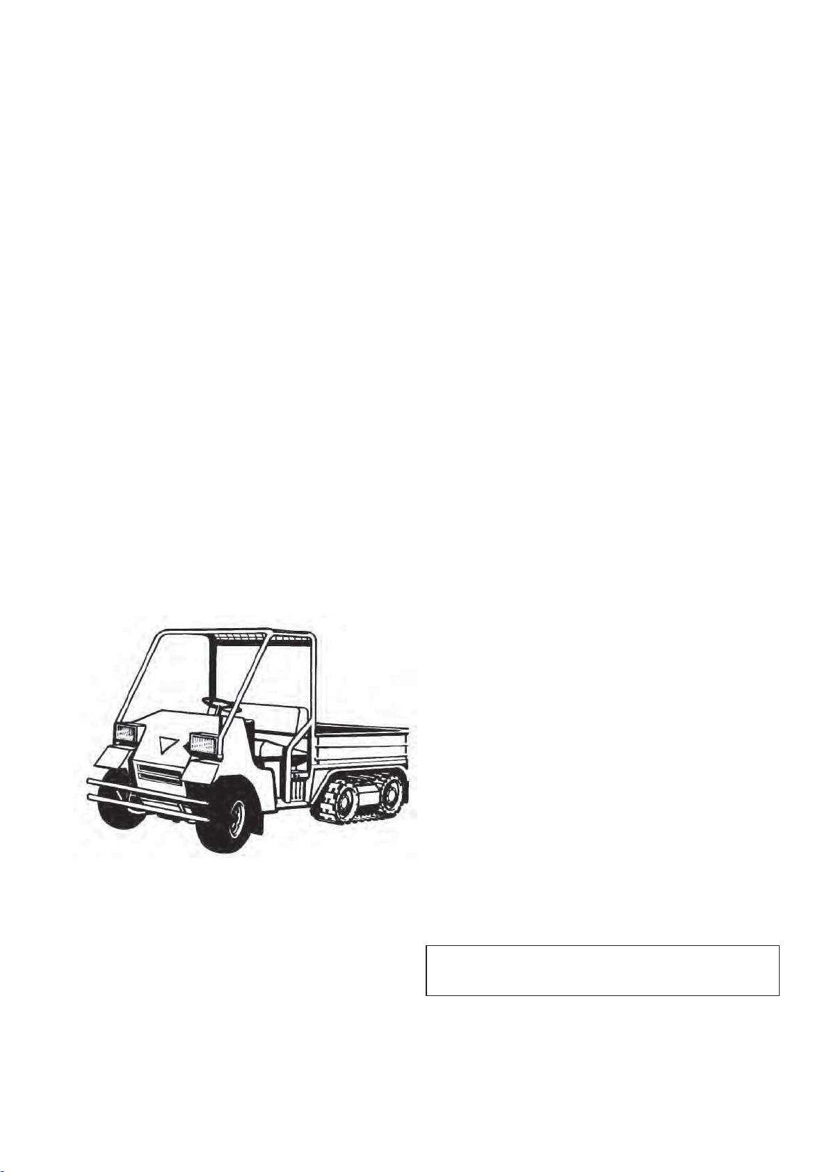
The TF Series Trailed Feeders are designed for feeding livestock, through deposition of pre-defined drops of
feed, onto clear ground.
The TF Series operate with an electric motor mechanism, ensuring accurate disposition, and industry lead-
ing ground clearance. The rotor and wiring mechanism are all IP67 rated, to ensure trouble-free usage in
even the toughest winter conditions.
The TF350 has approximately 350kg carrying capacity (feed material dependant), a galvanised metal
hopper and PVC cover. Standard wheels are 22x11x8” flotation, with optional heavy duty 24x12x12”
traction or road going tyres available.
These machines should however only be used to perform tasks for which they were designed - use of the
machine for any other function may be both dangerous to persons, and potentially damaging to components.
Use of the machine beyond the stated usage may invalidate any applicable warranty, as well as being poten-
tial in breach of applicable safety regulations.
Identification
Each machine is fitted with a serial plate which details the following:
1. Model
2. Date of Manufacture (DOM)
3. Serial Number
4. Mass
When enquiring regarding spares or additional equipment, ensure you have this information to hand.
Specification
Width (m)
Height (m)
Length (m)
Mass Ap-
prox.(kg)
Drops per
minute
Ground
Clearance
TF350
1.52
1.05
1.80
135
25
300-
350mm
Page 11
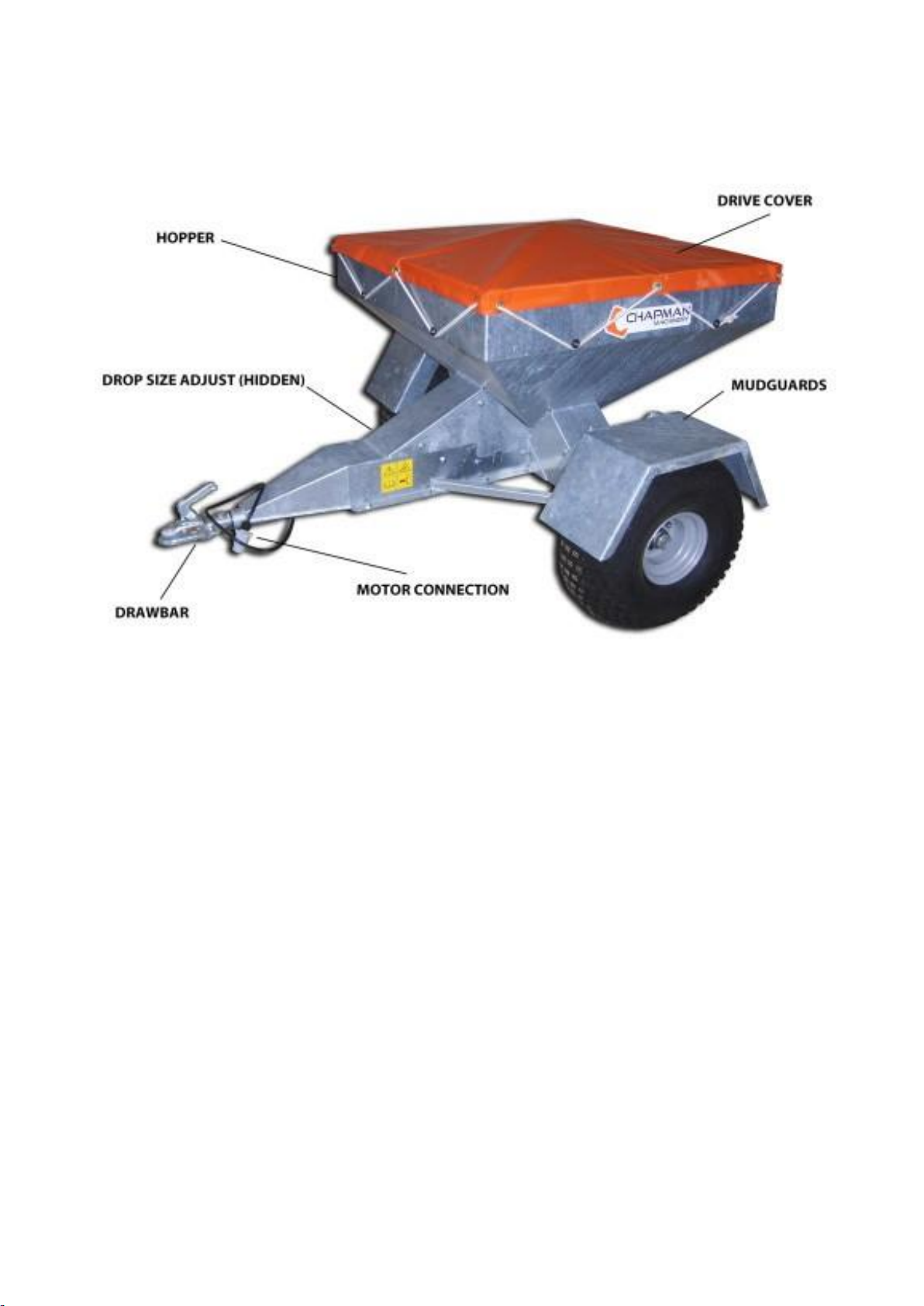
Component Identification
Optional Equipment
-Traction Tyres
-Extension Sides
-Livestock Fender Bar
-TwinAxle
-Hard TopBale Rack
-Road legal kit
-Additional ControlBox
Contact your distributor or Chapman Machinery for more information on optional equipment.

Page 12
Implement Decals
If your implement does not contain all of the decals shown below, please contact Chapman Engineering for
replacement decals before use.
Note: All decals must be present and visible. It is imperative that these are replaced if damaged to prevent
potential harm to users.
* Carefully read operators manual before handling this machine. Observe instructions and safety rules when
operating.
*Caution - Entanglement Hazard. Keep hands away from moving parts

Page 13
Attachment
Before Attaching the Machine
Before attachment, ALWAYS ensure the following:
- All safety guards & decals are in good working order and correctly fitted
- Lubrication points have been lubricated as per scheduled maintenance period
- The tyres are free of damage and inflated to the correct pressure
- Electrical connections are free of dirt and moisture
Attaching the Machine
NOTE: This machine is designed to attach to the towing vehicle through a 50mm diameter ball hitch.
1. Reverse the towing vehicle up to the machine.
2. Attach the machine onto the towing vehicle’s coupling.
3. Attach the control cable to the control socket fitted on the towing machine, ensuring a secure connection.
WARNING: ENSURE CONTROL EQUIPMENT IS SECURELY ATTACHED TO THE TOWING
VEHICLE BEFORE USE!
4. If required, check and adjust the drop size to suit the material being distributed.
1. Wire Plug
a. Wire Plug supplied with kit –cut approx. 30mm of outer sheath off and shorten BROWN
cable by 8mm. Wiring Code:
i. Brown = 7 = Motor –
ii. Red = 3 = Motor +
iii. Green = 5 = Sensor Brown Cable
iv. White = 1 = Sensor White Cable.
b. 2x 40mm lengths of black heat shrink tubing will be required as the plug is designed for a
larger cable diameter than is being used on these machines, so 2 pieces of heat shrink must be
heat shrunk onto the cable at the right point to allow the cable grip to function!
Page 14
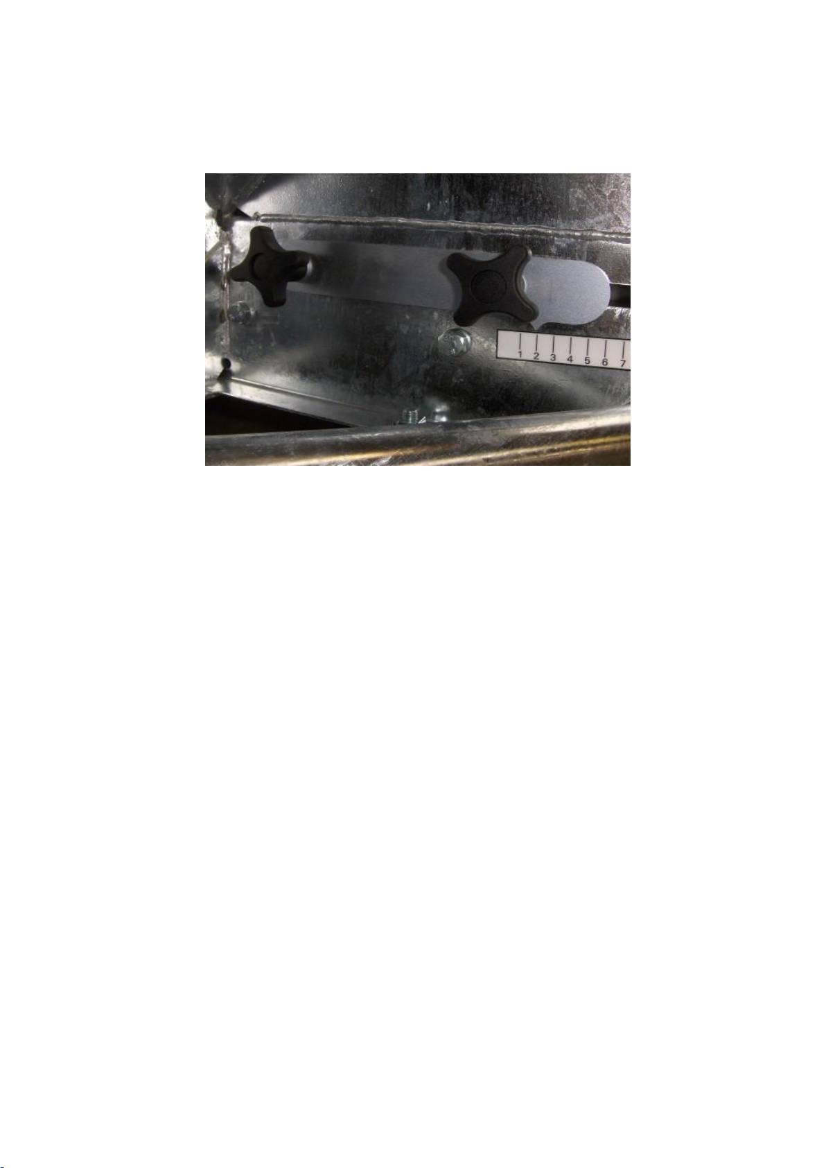
Drop Size Adjustment & Calibration
Initially set the Feed adjustment plate to setting 4, as indicated by the arrow on the drop adjustment plate.
Toadjust, loosen BOTH hand wheels, and slide the unit forwards or backwards to the desired value. Tighten
securely.
Setting 1: Minimum drop size Setting 8: Maximum dropsize
Fill the hopper 50% full of the feed to be distributed. With the machine attached to the towing vehicle and
on level ground, switch the control box on and deposit 10 drops of feed into a bucket. Measure the weight of
the deposited feed, and divide by the number of drops (in this case 10) to give the weight per drop.
Adjust the feed adjustment plate as required to increase or decrease the drop size, checking after each ad-
justment for the average drop size. Individual drop sizes can vary, especially with large granular materials
(eg. cobs) or with feedstuff containing molasses, so it is important to average the drop size over a number of
drops.
It is recommended that the feed be deposited in round numbers, ie. 1kg, 1.5kg, 2kg etc. This allows easy
calculation of required number of drops for different livestock numbers.
The drop setting will differ between feedstuff, due to the different particulate size and any binding agents
such as molasses. Its is strongly recommended to re-calibrate if you change feed make-up or consistency.
Once you have set the machine to the desired drop size, securely tighten the two retaining handwheels to
ensure this does not change during use.

Page 15
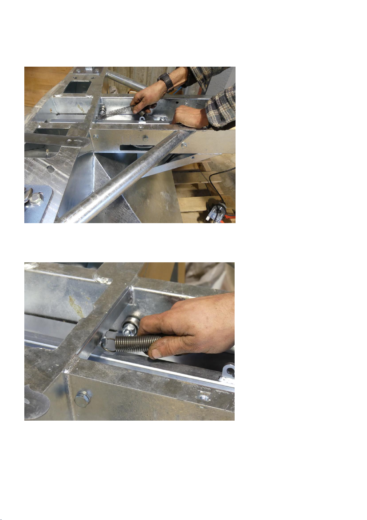
Spring Change / Replacement
If you are using the TF350 for a molasses based feed, cobs or rolls. You will need to change the spring which
is used to open/close the shutter.
1. REMOVE THE GUARD WHICH IS LOCATED UNDER THE DRAW BAR USING A 17MM SOCKET
2. THERE WILL BE A SPRING ALREADY ATTACHED (SEE BELOW) THIS SPRING IS USED FOR A
MORE FINER FEED SUCH AS CORN AND ROLLED BARLEY
Page 16
3. REMOVE THE SPRING BY UNHOOKING IT FROM BOTH END
4. REPLACE THIS WITH THE STRONGER SPRING.

Page 17
Sensor Change / Adjustment
If your control box is showing an F1 error and not counting correctly, you may have a problem with
the connectors and/or the sensor may need adjustment.
First, check the plug and socket connection between the control box and the feeder –THIS IS THE
MOST COMMON CAUSE OF PROBLEMS! If required check continuity with a multi-meter.
Plug/socket wiring; Brown = 7 = Motor –
Red = 3 = Motor +
Green = 5 = Sensor Brown Cable
White = 1 = Sensor White Cable.
If the connectors are functioning correctly then the unit may need adjustment of the sensor and
magnet located within the machine.
Procedure
1. Tilt the drawbar upwards so the machine is resting on the wheels and end of the mudguards,
this will allow easier access. Remove the belly plate using a 17mm socket on the 8 bolts.
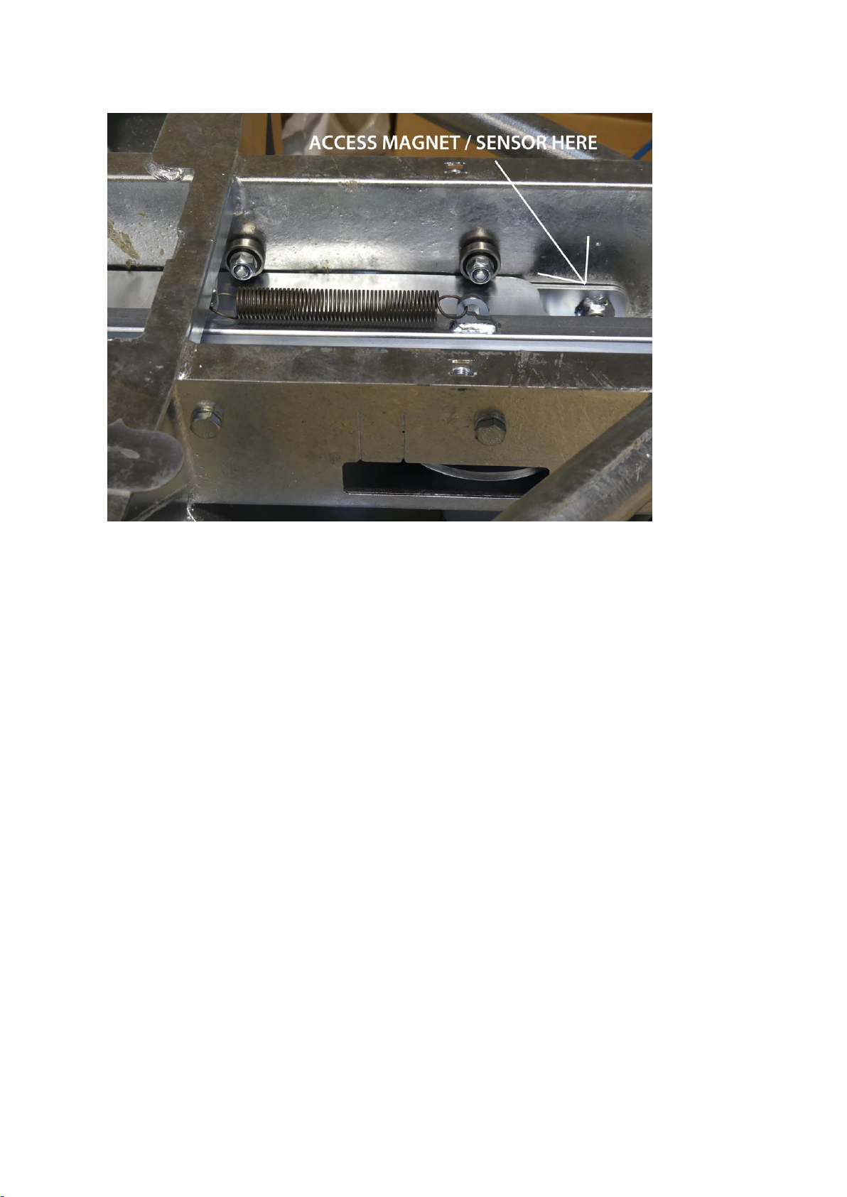
2. The sensor can be accessed though the recess in the slide plate shown in the RH corner of
the image below. You should not need to remove the slide plate to access the sensor. If you
do need to remove the slide plate for access, this can be achieved by unclipping the spring
from the slide plate and removing the 5 x bearings and associated bolts which locate the
Page 18
plate. TAKE NOTE OF THE NUMBER OF WASHERS AS THESE NEED TO BE RE-FITTED
IN THE SAME ORDER TO ENSURE THE SLIDE MOVES SMOOTHLY.
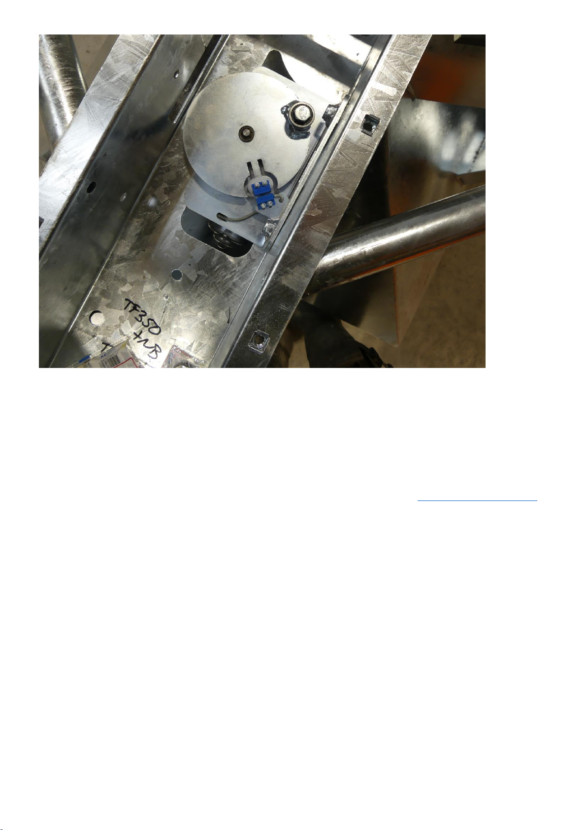
3. In the Picture below you can see the sensor (with the wire) and the magnet (fitted to the disc)
are facing each other with approximately 2mm gap between them. The sensors also need to
be aligned vertically (so that they are approximately level with each other).
If required you can bend the sensor support bracket up or down to get vertical alignment, and
you can move the sensor in or out on the slotted holes to get horizontal alignment.
FOR MACHINES USED WITH DUSTY FEED OR FEED WITH ADDITIVES SUCH AS
MOLLASES, BUILD UP OF DIRT CAN AFFECT THE SENSOR OPERATION –IN THIS
CASE CLEAN WITH A LOW-PRESSURE WATER JET.
Page 19
4. Parts are re-fitted as a reverse of removal, taking care to ensure all bolts are secure and
tight. If adjustments have been made to the sensor, ensure the cable is secured with cable
ties or similar to prevent accidental damage.
Once this has been checked and all dirt removed, your problem should be resolved.
we will be more than happy to help.

Page 20
Control Box
2 Button Model (UNTIL October 2015)
The TF Series control box has a two-button operation, and a three-digit display, capable of counting up to
999 drops.
The LH button switches the unit on, and a subsequent press of the LH button will start operation of the unit.
Afurther single press will pause operation. Holding the LH button for three seconds will reset the counter to
zero. The RH Button switches the unit off fully, with negligible powerconsumption.
NOTE: The unit MUST be stopped before switching off, as this allows the unit to ‘park’ in the correct
position. Switching the unit off without stopping may result in feed being spilt if the slider stops in the
open position!
The unit also contains a 15amp fuse. This can be seen mounted on the circuit board below the counter mod-
ule. If the fuse blows, the unit will light up to indicate the fault.
Specification
Supply Voltage: 12V DC nominal, 16V MAXIMUM
Power Consumption: 300mA + Motor power consumption when running
Operating Temperature: -20°C to +50°C
Fuse: 15A Automotive blade fuse with integrated failure LED
Operating life: 100,000 cycles
Protection rating: IP67
Incorrect polarity protection: Yes, diode.
Operation
1. Press the LH switch to turn the unit on. The display will perform a self-test for approximately 3
seconds. Once the default count (zero) shows, the unit is ready to use.
2. Tostart the motor, press LH switch. The counter will update from 0 to 999 as the motor operates. Themo-
tor and counter will continue to operate until it is paused or switchedoff.
Other manuals for TF350
1
This manual suits for next models
1
Table of contents
Other Chapman Utility Vehicle manuals

Popular Utility Vehicle manuals by other brands


FEATHERLITE TRAILERS
FEATHERLITE TRAILERS Horse Trailer owner's manual

Egholm
Egholm City Ranger 2250 Operator's manual

Woodland Mills
Woodland Mills PATHLANDER Operator's manual

Silver Eagle
Silver Eagle VAST-20W Operation, service & parts manual

Toro
Toro Workman 07347 Operator's manual

Toro
Toro 7213 Operator's manual


