Toro Workman 07347 User manual

FormNo.3392-713RevB
1/3AreaPlatformLift
Workman®Heavy-DutyUtilityVehicle
ModelNo.07347—SerialNo.315000001andUp
Registeratwww.T oro.com.
OriginalInstructions(EN)*3392-713*B

WARNING
CALIFORNIA
Proposition65Warning
Thisproductcontainsachemical
orchemicalsknowntotheStateof
Californiatocausecancer,birthdefects,
orreproductiveharm.
Useofthisproductmaycauseexposure
tochemicalsknowntotheStateof
Californiatocausecancer,birthdefects,
orotherreproductiveharm.
Introduction
Readthisinformationcarefullytolearnhowtooperate
andmaintainyourproductproperlyandtoavoid
injuryandproductdamage.Youareresponsiblefor
operatingtheproductproperlyandsafely.
YoumaycontactT orodirectlyatwww.Toro.comfor
productandaccessoryinformation,helpndinga
dealer,ortoregisteryourproduct.
Wheneveryouneedservice,genuineToroparts,or
additionalinformation,contactanAuthorizedService
DealerorT oroCustomerServiceandhavethemodel
andserialnumbersofyourproductready.
Thismanualidentiespotentialhazardsandhas
safetymessagesidentiedbythesafety-alertsymbol
(Figure1),whichsignalsahazardthatmaycause
seriousinjuryordeathifyoudonotfollowthe
recommendedprecautions.
g000502
Figure1
Thismanualuses2wordstohighlightinformation.
Importantcallsattentiontospecialmechanical
informationandNoteemphasizesgeneralinformation
worthyofspecialattention.
Contents
Safety.......................................................................3
BeforeOperating................................................3
WhileOperating..................................................3
Maintenance.......................................................3
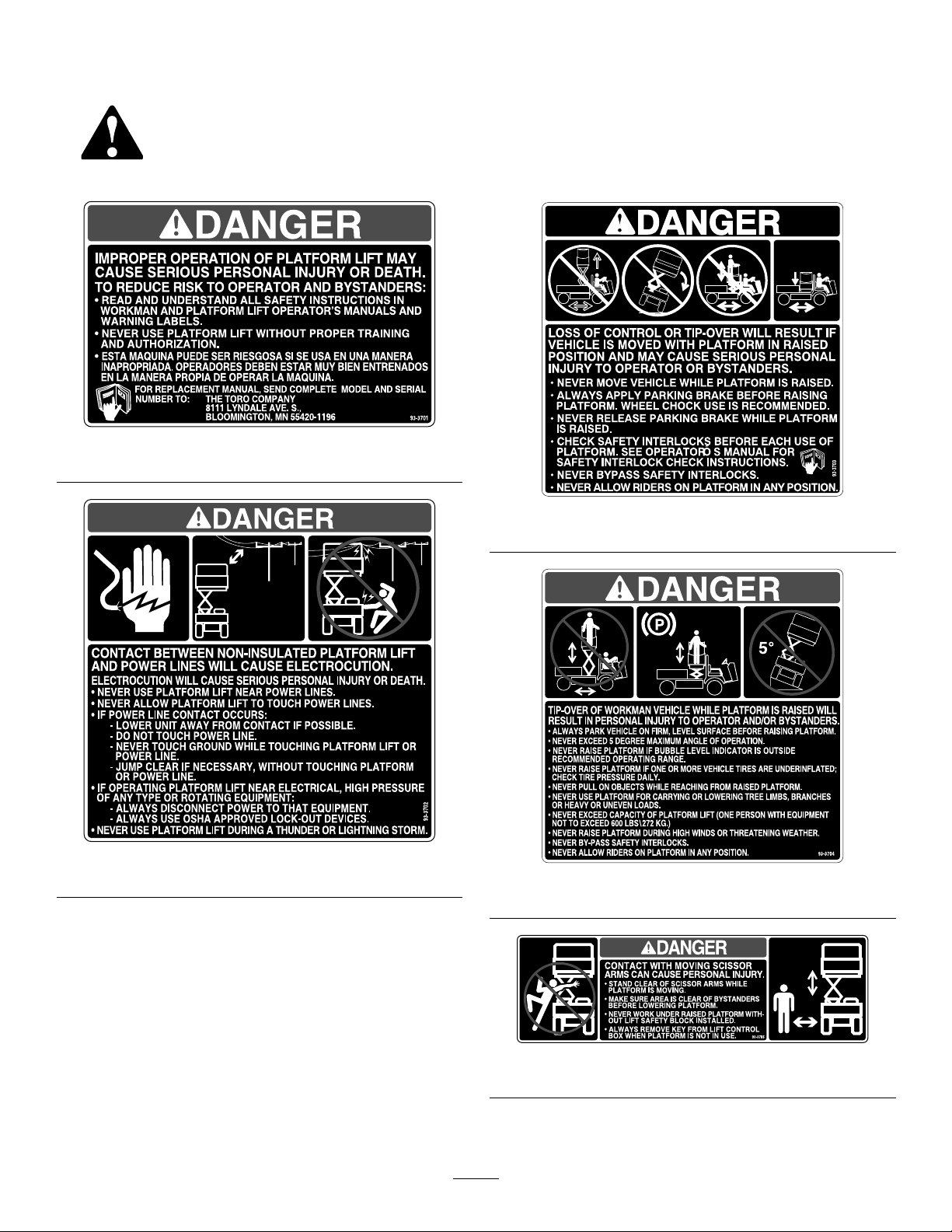
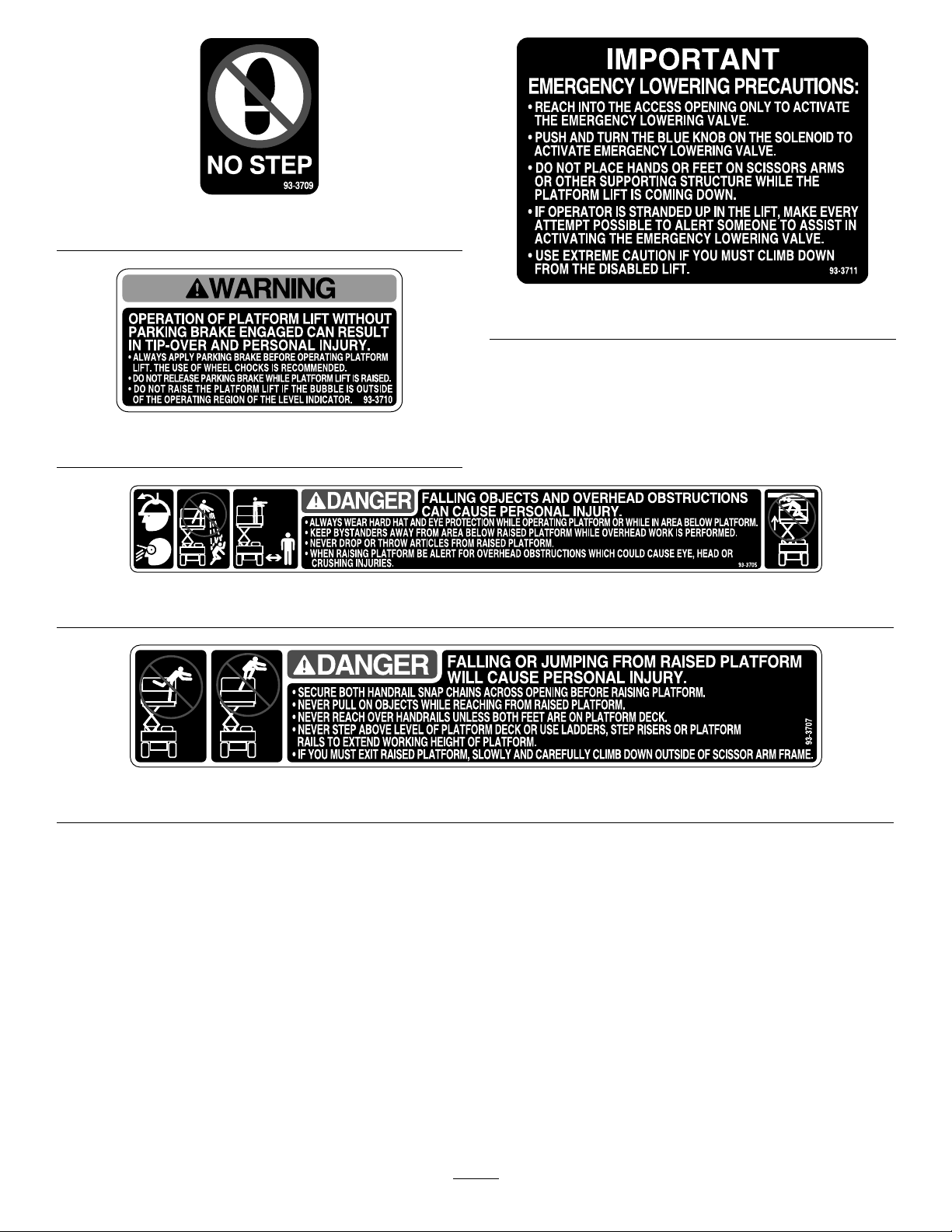
SafetyandInstructionalDecals..........................4
Setup........................................................................6
1PreparingtoInstalltheKit................................7
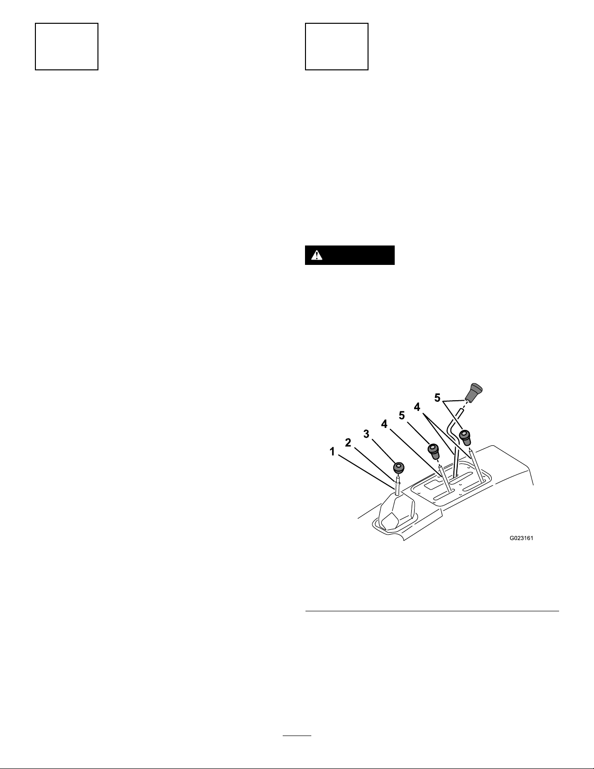
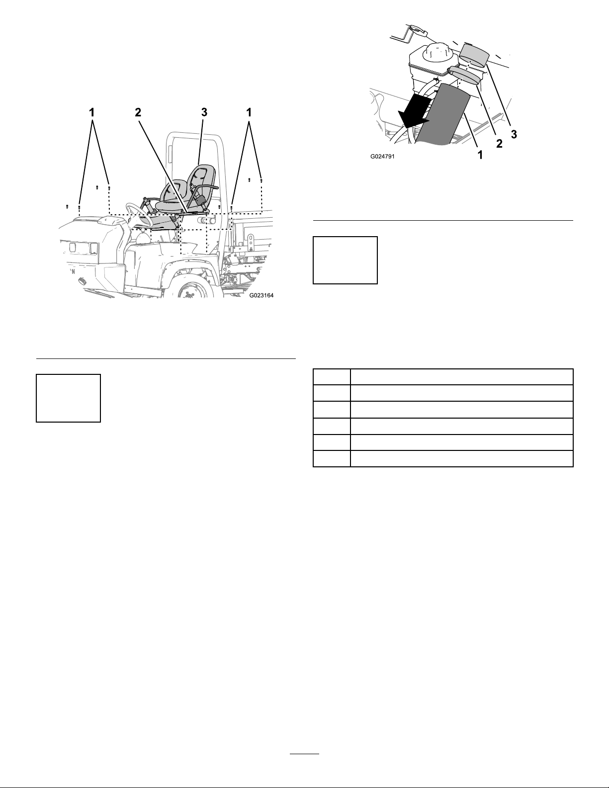
2RemovingtheCenterConsole,Seat
Shroud,andSeatAssemblies.........................7
3RemovingtheCVTCoolingDuct
(HDX-Autoonly)..............................................9
4InstallingtheMainWireHarnessand
Relays.............................................................9
5MountingtheParkingBrakeSwitch................10
6MountingtheRearLevelSwitch.....................12
7InstallingtheHood,ROPSShieldShroud,
Seats,SeatShroud,ConsoleCover
Plates,andCVTIntakeHose(HDX-Auto
only)..............................................................13
8MountingtheLiftontotheMachineFrame
......................................................................13
9ConnectingtheWireHarnessandBattery
......................................................................14
10MountingtheBubbleLevelIndicator.............15
11InstallingtheDecals.....................................16
ProductOverview...................................................17
Controls...........................................................17
Operation................................................................18
CheckingtheOilLevel......................................18
CheckingtheTirePressure...............................18
EngagingSafetyLocks.....................................18
OperatingtheLift..............................................19
OperatingTips.................................................21
Maintenance...........................................................22
CheckingtheSafetyCircuits.............................22
MaintainingtheBattery.....................................23
©2018—TheToro®Company
8111LyndaleAvenueSouth
Bloomington,MN554202
Contactusatwww.Toro.com.
PrintedintheUSA
AllRightsReserved

Safety
BeforeOperating
•Readandunderstandthecontentsofthismanual
beforeoperatingtheplatformlift.Becomefamiliar
withallcontrolsandknowhowtostopthemachine
quickly.Areplacementmanualisavailableat
www.Toro.com.
•Donotallowchildrentooperatethelift.Donot
allowadultstooperatetheliftwithoutproper
instruction.
•Keepallshieldsandsafetydevicesinplace.If
asafetydevice,shieldordecalmalfunctions,
becomesdamagedorillegible,replaceitbefore
operationiscommenced.T oensurethattheliftis
insafeoperatingcondition,tightenanyloosenuts,
bolts,andscrews.
WhileOperating
•Donotusethemachinenearelectricalpowerlines.
Neverallowtheplatformlifttotouchpowerlines.
•Donotusetheplatformliftduringlightning,
thunderstorms,orhighwinds.
•Donotmovethemachinewhiletheplatformis
raised.
•Engagetheparkingbrakebeforeraisingthe
platform.Useawheelchock.
•Neverreleasetheparkingbrakewhiletheplatform
israised.
•Checkthesafetyinterlocksbeforeeachuseofthe
platform.SeethemachineOperator’sManualfor
safetyinterlockcheckinstructions.
•Donotbypassthesafetyinterlocks.
•Donotallowridersontheplatforminanyposition.
•Alwaysparkthemachineonarm,levelsurface
beforeraisingtheplatform.
•Donotexceeda5–degreemaximumangleof
operation.
•Donotraisetheplatformifthebubblelevel
indicatorisoutsidetherecommendedoperating
range.
•Donotraisetheplatformif1ormoreofthe
machinetiresareunderinated;checkthetire
pressuredaily.
•Donotpullonobjectswhilereachingfromaraised
platform.
•Donotusetheplatformforcarryingorlowering
treelimbs,branches,orheavyorunevenloads.
•Donotexceedthecapacityoftheplatformlift;1
personwiththeequipmentshouldnottoexceed
272kg(600lb).
•Alwayswearahardhatandeyeprotectionwhile
operatingtheplatformorwhileinareabelowthe
platform.
•Donotdroporthrowarticlesfromaraised
platform.
•Whenraisingtheplatform,beawareofoverhead
obstructionsthatcouldcausebodilyinjuries.
•Standclearofthescissorarmswhiletheplatform
ismoving.
•Ensurethattheareaisclearofbystandersbefore
loweringtheplatform.
Maintenance
•Alwaysremovethekeyfromtheliftcontrolbox
whentheplatformisnotinuse.
•Ensurethattheliftisinasafeoperatingcondition.
Keepallnuts,bolts,andscrewstightened.
•Donotworkunderaraisedplatformwithoutthelift
safetyblocksinstalled.
3

SafetyandInstructionalDecals
Safetydecalsandinstructionsareeasilyvisibletotheoperatorandarelocatednearanyarea
ofpotentialdanger.Replaceanydecalthatisdamagedormissing.
decal93-3701
93-3701
decal93-3702
93-3702
decal93-3703
93-3703
decal93-3704
93-3704
decal93-3706
93-3706
4

decal93-3709
93-3709
decal93-3710
93-3710
decal93-3711
93-3711
decal93-3705
93-3705
decal93-3707
93-3707
5

Installation
LooseParts
Usethechartbelowtoverifythatallpartshavebeenshipped.
ProcedureDescriptionQty.Use
1Nopartsrequired–Preparetoinstallthekit.
2Nopartsrequired–Removethecenterconsole,seat
shroud,andseatassemblies.
3Nopartsrequired–RemovetheCVTcoolingduct
(HDX-Autoonly).
Mainwireharnesswithrelays1
Cabletie7
Screw(1/4x3/4inch)2
Nut(1/4inch)2
Fuse1
4
Minifuse(WorkmanHDX-Autoonly)1
Installthemainwireharnessandrelays.
Parkingbrakeswitch1
Hex-headscrew(3/8inch)2
Wireharness—3ftextension(HDX-Auto
only)1
Bracket(HDX-Autoonly)1
Bolt—1/4-20(HDX-Autoonly)1
Plate(HDX-Autoonly)1
Locknut(HDX-Autoonly)1
5
Flatwasher(HDX-Autoonly)3
Mounttheparkingbrakeswitch.
Rearlevelswitchbracket1
Rearlevelswitchwiththeharness1
6Washer2
Mounttherearlevelswitch.
7Nopartsrequired–
Installthehood,ROPSshieldshroud,
seats,seatshroud,consolecover
plates,andCVTintakehose(HDX-Auto
only).
Reinforcingplate2
FlangeHDcapscrew(3/8x1inch)4
8Flangenut(3/8inch)4
Mounttheliftontothemachineframe.
Batterycablewithboot1
9Negativebatterycable1Connectthewireharnessandbattery.
10Bubblelevelindicator1Mountthebubblelevelindicator.
Operationdecal1
11No-stepdecal2Installthedecals.
The1/3platformliftisdesignedtobeusedonlywithaWorkmanVehicleandmustbemountedwiththewire
harness,level,decals,switches,andallinterlockswitchesinstalled.The1/3platformliftwillonlyworkon
Workman3000andWorkman4000Seriesmachineswithserialnumbers240000001andupandallWorkman
HD,HDX,HDX-D,andHDX-Autovehicles.
6

1
PreparingtoInstalltheKit
NoPartsRequired
ForWorkman3000andWorkman
4000SeriesmachineswithSerial
Numbers240000001andUp
1.Positionthemachineonaclean,levelsurface,
shutofftheengine,engagetheparkingbrake,
andremovethekeyfromtheignitionswitch.
2.Disconnectthepositivecablefromthebattery.
3.Removethe6screwsandnutssecuringthe
bumpertothemachineframeandremovethe
bumper.
4.Removethe7screwssecuringthefronthoodto
themachineframeandremovethehood.
ForWorkmanHD,HDX,HDX-D,
andHDX-Automachines
1.Positionthemachineonaclean,levelsurface,
shutofftheengine,engagetheparkingbrake,
andremovethekeyfromtheignitionswitch.
2.Disconnectthepositivecablefromthebattery.
3.Raiseorremovethebedfromthemachineif
equipped.
Note:RefertothemachineOperator’sManual
formoredetailedinformationonraisingand
removingthebed.
4.Removethehood.
Note:RefertothemachineOperator’sManual
formoredetailedinformationonremovingthe
hood.
2
RemovingtheCenter
Console,SeatShroud,and
SeatAssemblies
NoPartsRequired
RemovingtheCenterConsolefor
Workman3000,4000,HD,HDX,
andHDX-DMachines
CAUTION
Pressurizedhotcoolantescapingcancause
seriousburns.
Allowtheenginetocoolenoughtotouch
beforetheremovingoverowtubeorradiator
cap.
1.Unscrewandremoveallknobsfromthecontrol
leversandfromthegearshiftlever(Figure2).
g023161
Figure2
1.Gearshiftlever4.Controllever
2.Jamnut5.Controlknob
3.Shifterhandle
2.Removethejamnutfromthegearshiftlever
(Figure2).
3.Removethe6screwssecuringtheoutsideedge
ofthecoverplateofthecenterconsoletothe
chassisandremovethecoverplate(Figure3).
7

g023165
Figure3
1.Screw2.Coverplate
4.Disconnectthereservoirhosefromtheradiator
andplugorclampittoretaincoolant(Figure3).
Note:Ifyourmachineisequippedwithablack
pressurizedtank,leavethehosesconnected
andliftthetankofftheshroud.
5.RemovetheoperatorshieldfromtheROPS.
RemovingtheCenterConsole
PanelfromtheWorkmanHDX-Auto
Machines
1.Removeallknobsfromconsoleleversandfrom
thetransmissionleverbyrotatingtheknobs
counterclockwise(Figure4).
g024571
Figure4
1.Brakelever5.Transmissionlever(L
position)knob
2.Hydraulic-liftleverknob6.Hydraulic-liftlock(locked
position—left)
3.Speed-rangeleverknob7.Speed-rangelever(A
position)
4.Transmissionleverknob
2.Removethe4hex-headscrewsthatsecurethe
shift-indicatorcovertotheseatshroud(Figure
5).
g024588
Figure5
1.Indicatorconnector4.Controlcover
2.Shift-indicatorcover5.Machine-harness
connector
3.Hex-headscrews
3.Lifttheshiftindicatorup,disconnectthe
indicatorconnectorfromthemachine-harness
connector,andremovetheindicatorcoverfrom
themachine(Figure5).
4.Removethe6hex-headscrewsthatsecurethe
controlcovertotheseatshroud,andremovethe
controlcover(Figure5).
8

RemovingtheSeatsfromthe
Machines
Removethe8socket-headboltsthatsecuretheseat
railsoftheseattothechassisandremovetheseats
(Figure6).
g023164
Figure6
1.Socket-headbolts3.Seat
2.Seatrail
3
RemovingtheCVTCooling
Duct(HDX-Autoonly)
NoPartsRequired
Procedure
RemovethehoseclampthatsecurestheCVTcooling
ducttotheangeoftheCVTintakeatthebackofthe
ROPSpanelonthepassengerside(Figure7).
g024791
Figure7
1.CVTintakehose3.Intake-tubeconnector
2.Hoseclamp
4
InstallingtheMainWire
HarnessandRelays
Partsneededforthisprocedure:
1Mainwireharnesswithrelays
7Cabletie
2Screw(1/4x3/4inch)
2Nut(1/4inch)
1Fuse
1Minifuse(WorkmanHDX-Autoonly)
FortheWorkman3000and
Workman4000Seriesmachines
withSerialNumbers240000001
andUp
1.Inserttheendofthewireharness,withthemale
andfemalespadeterminalsonit,upthroughthe
openinginthemachineoorboard,towardthe
dashpanel,followingthemachinewireharness.
2.Securetheharnesstothemachinewireharness
with2cableties.
3.Locatethered/blackwireconnectedtoterminal
Ioftheignitionswitch.
4.RemovethewirefromterminalIandplugitinto
theappropriatewireharnessterminal.
5.Plugtheremainingharnessterminalontothe
ignitionswitchonterminalI.
9

6.Removethefastenerssecuringthewireharness
covertotheundersideofthemachineoorand
removethecover.
7.Routethewireharnessrearwardtotheconsole
area.
Note:Theharnessmustnotinterferewithany
hot(exhaust)ormovingparts.
8.Securetheharnesswithcableties.
9.Mounttherelaystotheleftframechannelwith
2screws(1/4x3/4inch)and2nuts(1/4inch)
asshowninFigure8.
Note:Ifthemachineisequippedwithhighow
hydraulics,locateanothersuitablemounting
location.
g010205
Figure8
1.Relays
ForWorkmanHD,HDX,HDX-D,
andHDX-AutoMachines
1.Inserttheendofthewireharness,withthemale
andfemalespadeterminalsonit,upthroughthe
openinginmachineoorboard.
2.Locateanemptyslotinthefuseblock.
Note:Ifthereisnotanemptyslotavailable,an
additionalfuseblockwillhavetobeadded.
3.Inserttheincludedfuseintotheemptyfuse
blockslotandconnectthewireharnessspade
terminaltothecorrespondingspadeterminalon
thefuseblock.
Note:ForHDX-Automachines,usethemini
fuse.
4.Covertheunusedterminalwithelectricaltape.
Note:Useeitherthemaleorfemaleterminal
thatcorrespondstoyourmachine.
5.Removethefastenerssecuringthewireharness
covertotheundersideofthemachineoorand
removethecover.
6.Routethewireharnessrearwardtotheconsole
area.
Note:Theharnessmustnotinterferewithany
hot(exhaust)ormovingparts.
7.Securetheharnesswithcableties.
8.Mounttherelaystotheleftframechannelwith
2screws(1/4x3/4inch)and2nuts(1/4inch)
asshowninFigure8.
Note:Ifthemachineisequippedwithhighow
hydraulics,locateanothermountinglocation.
5
MountingtheParkingBrake
Switch
Partsneededforthisprocedure:
1Parkingbrakeswitch
2Hex-headscrew(3/8inch)
1Wireharness—3ftextension(HDX-Autoonly)
1Bracket(HDX-Autoonly)
1Bolt—1/4-20(HDX-Autoonly)
1Plate(HDX-Autoonly)
1Locknut(HDX-Autoonly)
3Flatwasher(HDX-Autoonly)
MountingtheParkingBrake
SwitchfortheHDX-AutoMachines
TheHDX-Automachinehasaparking-brakeswitch
thatisusedforcontrollingthereardifferential.Leave
thisexistingswitchandwireharnessandinstallthe
parking-brakeswitchfromthiskitinthealternate
positiondescribedinthestepsbelow.
1.Looselyinstalltheparkingbrakeswitchontothe
bracket,usingtheplate,carriagebolt,andnut,
asshowninBoxAofFigure9.
10

g028254
Figure9
1.Carriagebolt4.Bracket
2.Plate5.Nut
3.Switch
2.Removethehairpin,clevispin,andwasher
securingtheparkingbrakecabletothe
bellcrank,asshowninBoxBofFigure9.
3.Place2washersontheclevispinandslideit
backintothepreviousposition;BoxCofFigure
9.
4.Placethewasherpreviouslyremovedaswellas
anadditionalwasherontotheendoftheclevis
pinandsecuretheclevispinwiththehairpin;
BoxCofFigure9.
5.Removethebolt(1/4-20x11/2inch)onthe
parkingbrakebellcrankasshowninBoxDin
Figure9.
6.Insertthebolt(13/4inch)withtheheadofthe
bolttotheright,slidethebracketwiththeswitch
ontothebolt,andsecuretheboltwiththenut
previouslyremoved;BoxEinFigure9.
7.Alignthetargeticonontheswitchwiththehead
oftheclevispinandtightentheswitch(Figure
10).
g028255
Figure10
1.Targeticonontheswitch2.Gap(between0.06and
0.1inch)
8.Ensurethatthegapbetweentheheadofthe
clevispinandtheswitchshouldbebetween
0.06and0.1inch.
Note:Ifthegapisnotcorrect,adjustthehead
ofthepinbymovingthepositionofthewashers
installedinsteps3and4.
9.Connecttheterminalfromtheliftharness
markedParkingBraketotheparking-brake
switch.
10.Locatetheloopbackconnectorlabeled1/3Lift
onthemachinewireharnesslocatedbelowthe
controlstotherearofthecontrolsbracket.
11.Removetheloopbackconnectorandconnect
ittothe3ftextensionharness.
12.Routetheextensionharnessuptowardthe
parkingbrake,followingthemachinewire
harness,andconnectittotheconnectoronthe
liftharnessmarked1/3VerticalLift.
11

MountingtheParkingBrake
SwitchWorkmanModelswitha
ManualTransmission
1.Mounttheparkingbrakeswitchtotheparking
brakemountwith2screwsasshowninFigure
11.
g007162
Figure11
1.Switch
2.Plugtheswitchwireconnectorintotheliftwire
connectorharness.
3.Removetheloopbackconnectorfromthe
machinewireharnesslabeled1/3lift.
4.Connecttheliftwireharnesstothemachine
wireharness.
6
MountingtheRearLevel
Switch
Partsneededforthisprocedure:
1Rearlevelswitchbracket
1Rearlevelswitchwiththeharness
2Washer
ForWorkman3000andWorkman
4000SeriesmachineswithSerial
Numbers240000001andUp
1.Removethelocknutssecuringthetopofthe
hitchplatetotherearaxle(Figure12).
g016822
Figure12
1.Hitchplate2.Levelswitchbracket
2.Usingtheuppersetofmountingholes,mount
thelevelswitchbrackettotherearaxlewiththe
locknutspreviouslyremoved.
3.Routetheswitchharnessforward,alongthe
differentiallockcabletotheleftsideofthe
machine.
Note:Theharnessmustnotinterferewithany
hot(exhaust)ormovingparts.
4.Securetheharnesstothedifferentiallockcable
withcableties.
ForWorkmanHD,HDX,HDX-D,
andHDX-Automachines
1.Removethecapscrewssecuringthehitchplate
totherearaxle(Figure13).
g016821
Figure13
1.Hitchplate2.Levelswitchbracket
2.Usingthelowersetofmountingholes,loosely
mountthe2washers,andleveltheswitch
12

brackettotherearaxlewiththecapscrews
previouslyremoved.
Note:Positionthewashersbetweenthehitch
plateandaxle.
3.Tightenthe4capscrews.
4.Routetheswitchharnessforward,alongshift
thecabletotheleftsideofthemachine.
Note:Theharnessmustnotinterferewithany
hot(exhaust)ormovingparts.
5.Securetheharnesstotheshiftcablewithcable
ties.
7
InstallingtheHood,ROPS
ShieldShroud,Seats,Seat
Shroud,ConsoleCover
Plates,andCVTIntake
Hose(HDX-Autoonly)
NoPartsRequired
Procedure
1.Installthehoodtotheframe.
2.InstalltheROPSshieldshroud,seats,seat
shroud,andconsolecoverplate,ifapplicable.
3.Installtheoverowtubetotheradiator.
4.WorkmanHDX-Autoonly:InstalltheCVT
intakehose.
5.Checkthecoolantlevelandllasneeded.
8
MountingtheLiftontothe
MachineFrame
Partsneededforthisprocedure:
2Reinforcingplate
4FlangeHDcapscrew(3/8x1inch)
4Flangenut(3/8inch)
Procedure
1.Removeanyaccessoriesmountedtothetopof
theframeinforwardposition;suchasa1/3bed,
powerplatform,orHDhitchframeextension
tubes(Figure14).
g006698
Figure14
1.Hitchframeextensiontube
2.Locateandremovethethreadedinsertfrom
themountingholeintheleftandrightframe
channelsasshowninFigure15.
g006699
Figure15
1.Framechannel2.Threadedinsert
13

Note:Topreventtheliftscissorarmsfrom
expanding,pickuptheplatformliftfromthe
bottomwhenpositioningitontheframe.
3.Positiontheliftontotheframe,aligningthe
mountingholeswiththeholesintheframe
(Figure16).
g006700
Figure16
1.Lift2.Reinforcingplate
4.Mounteachsideofthelifttotheframechannels
withareinforcingplateand2capscrews(3/8-16
x1inch)andangenuts(Figure16).
Note:Usethereinforcingplatesinrear
mountingholesonly.
Note:OnHD,HDX,HDX-D,andHDX-Automodels,
theframeisequippedwithweldnutssothattheange
nutsarenotrequiredtosecurethefrontoftheliftto
theframechannels.
9
ConnectingtheWire
HarnessandBattery
Partsneededforthisprocedure:
1Batterycablewithboot
1Negativebatterycable
Procedure
1.Plugtheconnectorsfromthefrontandrear
harnessintotheliftharness.
2.Locatetheoil-pressureswitchontheengineand
unplugthewireconnectedtotheswitch.
3.Routethegreenwirefromthefrontharnessand
connectittotheoilpressureswitch.
4.Plugthewirepreviouslyremovedfromtheoil
pressureswitchintotheharnesspiggyback
connector.
5.Connectthegroundwirefromthelifttothe
engineground.
6.Removethenutfromthepositivebatteryclamp
(Figure17).
7.Insertthepositivewirefromtheliftandthe
ringterminalendoftheredwirefromthefront
harnessontothecableclampscrewandloosely
secureitwiththenutpreviouslyremoved(Figure
17).
14

g017228
Figure17
1.Positiveliftwire3.Redwirefromfront
harness
2.Positivebatterycable
clamp
8.Ensurethatthewireisclearofallhotorrotating
parts.
9.Securetheharnesswithcableties.
10.Installthepositivebatterycabletothebattery.
11.Slidetherubberbootoverthepositiveterminal.
12.Installthenegativebatterycabletothebattery.
10
MountingtheBubbleLevel
Indicator
Partsneededforthisprocedure:
1Bubblelevelindicator
Procedure
Afxthebubblelevelindicatortothetopoftheconsole
coverasshowninFigure18.
g016811
Figure18
1.Bubblelevelindicator2.Operationdecal
15

11
InstallingtheDecals
Partsneededforthisprocedure:
1Operationdecal
2No-stepdecal
ForWorkman3000andWorkman
4000SeriesMachineswithSerial
Numbers240000001andUp
1.Afxtheoperationdecaltothetopoftheconsole
coverasshowninFigure18.
2.Afxtheno-stepdecaltothetopofeachfuel
tankmountingstrapasshowninFigure19.
g006709
Figure19
1.No-stepdecal
ForWorkmanHD,HDX,HDX-D,
andHDX-AutoMachines
1.Afxtheoperationdecaltothetopoftheconsole
coverasshowninFigure18.
2.Afxtheno-stepdecalstothetopoftheradiator
asshowninFigure20.
g010211
Figure20
1.No-stepdecal
16

ProductOverview
Controls
g016810
Figure21
1.Pendantcontrol3.Downbutton
2.Upbutton4.Keyswitch
UpButton
PresstheUpbuttontoraisethelift(Figure21).
DownButton
PresstheDownbuttontolowerthelift(Figure21).
KeySwitch
Rotatethekeyswitchtoauthorizetheuseofthelift.
Removethekeyfromtheliftpendantcontrolswitchto
preventoperationoftheliftwheneverthemachineis
leftunattended(Figure21).
EmergencyLoweringValveKnob
Pushtheblueknobinward,rotateit90degrees
counterclockwise,andpullitouttoactivatethe
emergencyloweringvalve(Figure22).
Pushtheblueknobinward,rotateit90degrees
clockwise,andpullitouttostoptheliftandreturnit
tonormaloperation.
g016809
Figure22
1.Emergencyloweringvalveknob(blueknob)
17

Operation
CheckingtheOilLevel
Capacity:1.5USqt
Theliftreservoirislledatthefactorywith5W30oil.
Checkthelevelbeforetheliftisrstoperatedand
every8hoursordaily,thereafter.
1.Positionthemachineonalevelsurface.
2.Raisetheliftandengagethesafetylocks;refer
totheEngagingSafetyLocks(page18).
Note:Ifyoucannotraisetheliftduetothelack
ofoilinthereservoir,raiseitwithahoistand
ensurethatthesafetylocksareengagedto
exposereservoirbreathercap.
3.Theoillevelcanbeviewedthroughthereservoir.
Iftheoillevelislow,proceedtonextstep.
4.Cleantheareaaroundreservoirbreathercap
(Figure23).
g016812
Figure23
1.Reservoircap
5.Unscrewthebreathercapfromthetopofthe
reservoir.
Note:Fluidshouldbewithin2inchesfromtop
ofreservoir.
6.Iflevelislow,addenoughoiltotheproperlevel.
Note:Donotoverll.
CheckingtheTirePressure
Checkthetirepressureevery8hoursordailyto
ensureproperlevels.
RefertothemachineOperator’sManualfortire
inationspecication.
EngagingSafetyLocks
1.Positionthemachineonalevelsurface.
2.Settheparkingbrakeandchockthewheels.
3.RotatetheignitionkeyswitchtotheONposition
withtheengineoff.
4.Whilestandingnexttomachine,graspthe
pendantcontrolandrotatetheliftkeyswitchto
theONposition.
5.Checktheoverheadclearanceandforany
obstructions.
6.PresstheUpbuttontoraisethelifthighenough
toengagethesafetylocks.
Important:Standclearofscissorarms
whileplatformismoving.
DANGER
Contactwithmovingscissorarmscan
causepersonalinjury.
•Standclearofthescissorarmswhile
theplatformismoving.
•Ensurethatareaisclearofbystanders
beforeloweringtheplatform.
•Neverworkunderaraisedplatform
withouttheliftsafetylocksengaged.
•Alwaysremovethekeyfromthelift
controlboxwhentheplatformisnot
inuse.
7.Rotatebothofthesafetylocks,fromtheir
storagepositions,untiltheyrestinsidethebase
frame,inthepathofthescissorsrollers(Figure
24).
18

g016813
Figure24
1.Safetylock(2)2.Scissorsroller(2)
DANGER
Theplatformliftcancrushandcause
personalinjury.
•Neverworkunderaraisedplatform
withouttheliftsafetylocksengaged.
•Neverusesafetyblockstosupporta
loadonthelift.
8.PresstheDownbuttononthependantcontrol
andlowertheliftuntiltherollersgentlycontact
thesafetylocks.
9.Oncethelocksarefullyengagedwiththe
scissorsrollers,continuetoholdtheDown
buttonfor5to10secondstorelievethepressure
withinthehydrauliccircuit.
10.Toremovesafetylocks,dothefollowing:
•Raiseliftslightly.
•Returnsafetylockstostorageposition.
OperatingtheLift
The1/3platformliftisdesignedtobeusedonlywith
aWorkmanmachineandmustbemountedwiththe
wireharness,level,decals,switches,andallthe
interlockswitchesinstalled.
DANGER
Improperoperationoftheplatformliftmay
causeseriouspersonalinjuryordeath.To
reducerisktoyouandbystanders,dothe
following:
•Readandunderstandallthesafety
instructionsintheWorkmanandPlatform
LiftOperator'sManualsandwarninglabels.
•Neverusetheplatformliftwithoutproper
trainingandauthorization.
Theelectricalcontrolsystemoftheliftrequiresthe
machinetobeparkedonaslopeoflessthana
5–degreeangle,parkingbrakeengaged,andthe
machinekeyintheONpositionwiththeengineshut
offtoactivatetheliftcircuit.
Operating
1.Settheparkingbrakeandchockthewheels.
2.RotatethekeyswitchtotheONpositionwiththe
engineoff.
3.Climbintotheplatformandsecurethesafety
chainsacrosstheentry.
4.Graspthependantcontrolandrotatetheliftkey
switchtotheONposition.
5.PresstheUpbuttontoraisetheliftandthe
Downbuttontolowerthelift(Figure21).
Note:Iftheengineoiliscold,itmaytake
severalsecondsfortheengineoilpressureto
bleeddownaftertheengineisshutoff.Thelift
doesnotoperateuntiltheoilpressureindicator
lightison.
WARNING
Operatingtheplatformliftwithoutthe
parkingbrakeengagedcanresultina
tip-overandpersonalinjury.
•Alwaysapplytheparkingbrakebefore
operatingtheplatformlift.Usewheel
chocks.
•Donotdisengagetheparkingbrake
whiletheplatformliftisraised.
•Donotraisetheplatformliftifthe
bubbleisoutsideoftheoperating
regiononthelevelindicator.
19

DANGER
Ifyoumovethevehiclewiththeplatform
intheraisedposition,alossofcontrol
ortip-overwillresult,causingpossible
seriouspersonalinjurytoyouor
bystanders.
•Nevermovethemachinewhilethe
platformisraised.
•Alwaysapplytheparkingbrakebefore
raisingtheplatform.Usewheel
chocks.
•Neverdisengagetheparkingbrake
whiletheplatformisraised.
•Checkthesafetyinterlocksbefore
eachuseoftheplatform.Seethe
machineOperator’sManualforthe
safetyinterlockcheckinstructions.
•Neverbypassthesafetyinterlocks.
•Neverallowridersontheplatformin
anyposition.
Iftheliftdoesnotoperate,dothefollowing:
•Ensurethattheignitionkeyandliftkeyarein
theONposition.
•Ensurethatthemachineisparkedonless
thana5–degreeangleslope.
•EnsurethattheparkingbrakeisintheON
position.
•Ensurethattheengineisshutoffandtheoil
pressurelightison.
6.Lowerliftallthewaydownuntilitstopsand
removethekeyfromtheliftpendantcontrol.
Important:Iftheengineshutsoffwhen
releasingtheparkingbrake,itmayindicate
thattheliftisnotcompletelylowered.The
machinecannotbedrivenwiththeliftraised
atanyheight.
DANGER
Contactbetweenthenon-insulated
platformliftandpowerlineswillcause
electrocution,causingseriousinjuryor
death.
•Neverusetheplatformliftnearpower
lines.
•Neverallowtheplatformlifttotouch
powerlines.
•Ifpowerlinecontactoccurs,dothe
following:
–Lowertheplatformliftawayfrom
contactifpossible.
–Donottouchthepowerline.
–Nevertouchthegroundwhile
touchingtheplatformliftorpower
line.
•Ifoperatingtheplatformliftnear
electrical,highpressure,orany
typeofrotatingequipment,dothe
following:
–Alwaysdisconnectthepowerto
thatequipment.
–AlwaysuseOSHAapproved
lockoutdevices.
•Neverusetheplatformliftduringa
thunderorlightningstorm.
Lowertheplatformliftandavoid
openareasintheeventofthreatening
weather.
20
Other manuals for Workman 07347
1
Table of contents
Other Toro Utility Vehicle manuals

Toro
Toro 07411EX User manual

Toro
Toro 7383 User manual

Toro
Toro Workman MD User manual

Toro
Toro 07277 Workman 2110 User manual

Toro
Toro Sand Pro 3040 User manual

Toro
Toro TransPro 200 User manual

Toro
Toro 127-7377 User manual

Toro
Toro Workman GTX Series User manual

Toro
Toro TransPro 80 User manual

Toro
Toro 7253 User manual