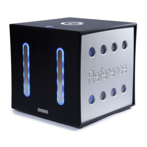
Chapter Audio Preface User manual

C H A P T E R P R E F A C E
Chapter
Preface Line Stage
Pre amplifier
The exception, not the rule...
www.chapteraudio.com

Table of Contents
2
Important Safety Instructions................................... 3
Thank You from Chapter.......................................... 4
Introduction.............................................................. 5
Unpacking you Pre-Amplifier................................... 6
Break In Period........................................................ 6
Installation................................................................ 7
Ventilation................................................................ 7
Operating Voltage and Mains Conditions................ 8
Design Features...................................................... 9
Top Panel................................................................. 10
Front Panel............................................................... 11 & 12
Rear Panel................................................................ 13
Remote Control......................................................... 14
Specifications............................................................ 15
Conformity & Acknowledgements............................. 16
Warranty Information................................................ 17
Contact Information.................................................. 17

Important Safety Instructions
Please read all instructions and precautions carefully before operating your
Chapter Preface Pre-Amplifier.
1 Please disconnect all items in your audio or AV system before connecting or
disconnecting any mains or interconnect cables, or when cleaning
your Chapter product.
2 Please ensure that your Chapter product is always terminated with a
three pin AC power cord. To prevent the possibility of shock all three
connections must be used.
3 To clean your Chapter product please use a soft damp cloth. Never use
flammable or combustible chemicals.
4 Never operate this product with any covers removed.
5 Never allow the inside of this unit to become wet, or pour / spill liquids
directly onto it .
6 Never block air flow through the vents on the top plate.
7 Never bypass any fuse.
8 Never replace a fuse with anything other than those specified.
9 There are no user serviceable parts within this product. If problems occur,
please contact your Chapter retailer.
10 Never expose this product to extremely high or low temperatures.
11 Unplug this product during lightening storms.
3

From all of us at Chapter...
Preface See through cover.
From dream to reality...
Thank you for choosing the Chapter Preface
Pre-Amplifier.
It has been designed and manufactured to the
highest possible standards in order
to give you many years of musical enjoyment.
4

The Chapter Preface Pre-Amplifier is a new ‘state of the art’ audiophile two-channel
line stage pre-amplifier.
The Pre-amp features a number of new design features along with scrupulous
attention to technical detail.
Our objective is to provide a product capable of great musicality and realism whilst
boasting exemplary technical specifications. By bringing together engineers and
designers with a lifetimes experience in audio and power system design we believe
this objective has been more than achieved.
The Chapter Preface is able to handle all of today’s high-resolution sources, with the
fidelity that you would expect of any Chapter product.
Our goal, as always, is to produce a true reference quality line stage. A product that
can be held in the highest regard from both objective and subjective perspectives.
After several years of research and development, we believe that we have
succeeded in fulfilling the requirements of even the most discerning audiophile.
Introduction
5

Unpacking your Pre-Amplifier
The shipping weight of your Chapter Preface Pre-Amplifier is 11 KG.
Therefore, under normal circumstances, one person should be able to unpack the
unit safely. If you are in any doubt, please obtain the assistance of a second person.
To avoid back injury whilst carrying your amplifier (or any other piece of heavy
equipment) please crouch with a straight back and use your leg muscles.
After unpacking your pre-amplifier, please retain all packaging for future transport. If
you move house or you need to ship your pre-amplifier, only the custom designed
flight case provided is acceptable. Any other method of shipping may result in
damage and such damage is not covered under warranty.
Please inspect your pre-amplifier for possible damage due to shipping. If you
discover any, contact your Chapter Audio dealer immediately.
Your Chapter Preface Pre-Amplifier will deliver excellent performance straight out of
the box, however, you should expect to hear it improve as it reaches its normal
operating temperatures and its various components ‘break-in’. In our experience the
most significant changes occur within the first 30 - 50 hours use, but the unit
will continue to improve in sound quality for about 100 hours, after which time it
remains quite consistent.
If the power is removed and reconnected to the pre-amplifier, you must allow a brief
‘warm up’ period for the unit to give off its best.
However, it is not recommended to leave your Chapter Preface Pre-Amplifier on
permanently.
Break In Period
6

Installation
Ventilation
Your Chapter Preface Preamplifier has been designed to fit into a good quality
equipment rack or amplifier stand. In most installations locating the pre amp near
the source components is best. By doing this you minimise the length of any
unbalanced interconnect cable that you may be using.
Where permitting, locate the power amplifier near the loudspeakers and use a long-
er pair of balanced interconnects to your Preface unit.
The advantage to this strategy lies in the fact that the interconnects carry low
current signals that are easily transmitted over distances with greater accuracy
than the high current signals required by loudspeakers.
Your Preface Pre-Amplifier will drive the most demanding of cable runs and amplifier
loads with ease.
The back of your Preface Pre amplifier has been laid out to keep every
connection accessible. We recommend that you leave some clearance behind the
unit to fit cables without having to bend them excessively.
In order to conform with CE regulations your pre-amp is fitted with a rocker
style power switch on the rear of the unit as well as a ‘standby’ switch on the top
plate. This rear mounted rocker switch disconnects power from the power supply,
resulting in effective disconnection of the amplifier from the AC mains.
Please allow your pre-amplifier to have at least five centimetres between the top
cover and the next shelf up on an equipment rack.
The circular vents on top of the pre-amp must not be obstructed, as this would
reduce the free flow of air through the unit.
7

Operating Voltage and Mains Conditions
A good quality three pin, 5 ampere IEC standard, detachable mains lead is
provided for use with your pre-amplifier. It is recommended that you use this lead.
Please contact us for advice if replacement is required.
The Chapter Preface uses several very low noise, double regulated, linear power
supplies to control digital, analogue and control circuitry. Using large custom made
screened transformers and a fastidious attention to circuit layout gives the unit
staggering noise performance, whilst an advanced mains monitoring system allows
the unit to ride through the most unsettled of mains conditions.
Unlike the award winning Chapter Two power amp, the input voltage from which the
Preface will operate is factory set to either 110V or 230V.
As the transformers in the Chapter Preface are custom made to our specification,
there is no difference in unit performance if operated at 230V 50Hz or 110V 60Hz.
Total audio performance is thus assured anywhere in the world.
8

Design Features
Finest Part Selection: The Preface uses the best sounding OPAMPS from Burr
Brown and Linear Technology. All electrolytic capacitors, are all ultra low ESR
Panasonic Gold series. On the power supply we use the finest sounding regulators
from LT and our own custom screened mains transformers. At Chapter we also use
the finest full emersion gold Printed Circuit Boards and ‘Melf’ surface mount
precision resistors.
Wide bandwidth: This is important in preserving the vital H.F. phase information
essential to stereo sound staging and realism. The output stage was designed spe-
cifically for its speed of response, further improved by a high-speed
input stage. Frequency compensation of the pre-amplifier is achieved in such a way
as to allow excellent phase and gain margin into complex amplifier loads without
compromising high frequency phase or power bandwidth.
Balanced ground layout: Cancels the ground currents that can cause
Inter-modulation distortion and crosstalk in a conventional stereo design.
Full Emersion Gold Printed Circuit Boards: Audio signals travel on gold track. As
you would imaging, compared to copper and gold plate this is a very expensive to
manufacture, but the sonic benefits are hugely tangible in terms of space, air and
dynamics.
Custom Designed Volume Control: At Chapter we auditioned many different
volume pots, all of which had their own traits. Instead of designing electronics to
counter the sonic signature of any particular pot, we have designed our own, using
a series of precision resistors and relays. This gives us unprecedented levels of
resolution with complete volume repeatability.
Large Very Low Noise PSU’s: The heart of the pre-amplifier, where digital,
analogue and control power supplies are derived from separate custom made 50VA
transformers, the finest Linear Technology regulators and Panasonic gold series
capacitors.
Acousteel Vibration Control System: In the Chapter Preface, vibrational energy
is reduced by up to 80%, effectively isolating the pre-amp from 15Hz upwards. By
using three sheets of aluminium bonded together with a special viscose-elastic
polymer and using this as the pre-amp base plate, vibrational energy
transmitted to the components within the unit are kept to a minimum.
9

Top Panel
Air Vents
‘Tact’ style standby
switch
When applying power to your Chapter Preface Pre-Amplifier for the first time please
ensure to operate the rear panel AC mains switch. This allows the pre-amp to
enter standby mode. Whilst in Standby mode the sensitive voltage gain stages are
still powered up to ensure that the unit will sound at its best after only a
short period of time. Whilst in standby mode the pre-amplifier draws around 3 watts.
Once the pre-amp is in standby mode the Perspex / Metal dome located on the top
of the amplifier will light red, and the knobs on the front panel will not be lit.
To fully activate the unit, touch the metal section of the dome located on the top of
the pre-amplifier, the disc will turn blue and the output relays will engage around 2
seconds later. The knobs on the front of the unit will both illuminate blue.
Alternatively, you can press either of the left or right hand knobs, as this will also
fully activate the unit.
To return the unit to standby mode, again touch the illuminated dome on
the top plate. If you wish to isolate the unit from the mains supply you must turn off
the amplifier using the rear panel mains AC switch.
If you will not be using the unit for long periods of time, for example going on
holiday, it is best to totally disconnect the amplifier from the AC mains by removing
the moulded plug from the wall socket.
10
Right Hand Knob

Front Panel
There are two knobs on the front of the Preface. The knobs will glow blue when
power is applied to the unit and unit is brought out of standby by either pressing the
top panl button or pressing either the right or left knobs.
The lights on the knobs will not change in intensity, and have been designed to stay
lit so that the unit may be used in low light conditions
Left Knob Functions. (In menu order)
Input (select)
Choose between any of the six available inputs. Rotating the knob to the desired
input will activate that input. From left to right these are TAPE, VIDEO, SAT, RADIO,
DVD, CD, PHONO
Output (Select)
Press the left hand knob to open up the output select menu. This gives you the
option to select your choice of active outputs. These are ‘BALANCED’ (default),
‘UNBALANCED’ or ‘BAL+UNBAL’.
Phase (Select)
Press the left knob once more to open up the Phase select menu. You can alter the
phase on any input. The choices are ‘NON INVERT’ (default) and ‘INVERT’.
Sleep Mode
Press the left knob once more opens up the Sleep mode menu. This feature allows
you to shut down the display and micro controller down after a time period selected
by you. To activate sleep mode rotate the knob from the ‘OFF’ position, after which
point you will be able to select the amount of time that the display remains active
before going into sleep mode. The options are from 5 seconds through to 60 sec-
onds in five second intervals. If a knob or the remote is used the Preface will come
out of sleep mode and re enter this mode after the set amount of time
has elapsed. The default setting is 20 seconds. If ‘OFF’ is selected, the
unit will always show the display and the micro controller will be active.
Pressing the left knob once again will cycle back to the input menu.
Input Select Knob - Left
11
Graphic Display
Volume Knob - Right
IR Receiver

Right Knob Functions (In menu order)
Volume control
To reduce the volume rotate the right knob anti clockwise, to increase the volume
rotate the knob in a clockwise direction.
At its most sensitive, the volume can be adjusted in 1dB steps from -86dB to
-60dB, 0.5dB steps from -60dB to -50dB and in 0.1dB steps from -50dB to +6dB
(input gain set to x2) or +9.4dB (input gain set to x3).
For convenience, there are four volume speeds that allow you to find your desired
volume quickly. For example, if you wish to increase the volume from -50dB to -7dB,
you can turn the knob slowly to increase the step size in 0.1dB increments, move
the knob a little quicker and the volume will increase in 0.2dB increments, the next
speed being 0.5dB and the final setting being 1dB steps at a time.
As the readings are true dB references, the volume you require is repeatable every
time.
Balance
Pressing the right hand knob brings up the balance menu. The default setting shows
‘0dB - 0dB’. You can adjust the balance by up to 6dB per channel. This works by
decreasing the volume of one channel. By turning the right hand knob in a clock-
wise direction, the left hand number will go down in level. EG ‘-6dB - 0dB’.
This is normal as you are lowering the volume on the left channel to favour the right,
and visa versa.
Input Gain
Press the right knob once more opens up the Input Gain menu. You can then alter
the gain of the selected input by choosing gain x2 (default) or gain x3. This is used
to normalise the levels between various sources.
Mute Function
To mute the output of the pre amplifier, press and hold in the right hand knob for two
seconds. To unmute the outputs rotate the right hand knob in either the clockwise or
anti-clockwise direction.
Front Panel continued
12

1 Filtered Mains input terminal:
To ensure the quality of the mains input to the Preface a filtered
IEC mains inlet is used. This also contains a 5A fuse
2 True Balanced Inputs x 2:
Labelled: Phono, CD
The Preface will accept analogue signals from sources with XLR outputs.
The pin assignments conform with the AES standard of pin 1 ground, pin 2
signal +, pin 3 signal - and the connector ground being chassis
ground. In order to maintain absolute phase, please check to make sure that
your chosen source component has the same pin assignments. If not you
can change the phase for that input through the option via the left hand control
knob.
3 Single-ended Inputs x 5:
Labelled: Tape, Video, Sat, Radio, DVD.
Your Chapter Preface accepts analogue signals via RCA single ended
interconnect cables on the aforementioned inputs.
4 Balanced and Single ended Outputs
Your Preface unit can drive both unbalanced and Balanced
cables runs simultaneously. The XLR outputs conform to the
AES standard as per the XLR input stage.
Rear Panel
13
AC input and filter True Balanced
Inputs
Single ended inputs Balanced and Unbalanced
outputs

Remote Control
Volume Up
Pressing this button on the handset, increases the volume on the pre amplifier.
Volume down
Pressing this button decreases the volume on the pre amplifier.
Power On / Off
This activates the unit from standby or returns the unit to standby mode.
Mute - On / Off
This mutes the outputs. Press this button again to un-mute the pre amplifier. The
Preface can also be un-muted by pressing the volume up or down keys on the
handset.
Option Select left /Right
This allows you to cycle between the individual inputs.
Enter
This button mimics the left hand knob. When pressing this button you can cycle
through the entire left knob menu structure (see page 11 for details), adjusting your
chosen parameters with the option select left or right keys.
Note: Battery Life on the handset is around 6 months. The unit takes 2 x AA batteries
and these can be replaced by unscrewing the bottom plate. When replacing the
batteries always ensure correct polarity is observed, and that the batteries
are both new.
Volume up
Option Select -Right
Power On / Off
Volume Down
Mute - On / Off
Option select - left
Enter Button
14

Specifications
Electrical
THD + N Less than 0.0006% (-106dB) at 1KHz. 22Hz to 22KHz bandwidth
Less than 0.004% (-86dB) at 1KHz. 10Hz to 500KHz bandwidth
IM Distortion Better than -115dB (19+20KHz dual tone test - 1 KHz product at 1V input)
Signal to Noise Better than -107dB (22Hz to 22KHz bandwidth.
Better than -93dB (10Hz to 500KHz bandwidth.
Frequency response DC to 90KHz +0 - 0.1dB (Driving 100K ohms, 85KHz driving 600 Ohms)
Cross talk (channel to channel) -120dBv at 1KHz, -100dB at 20KHz, -85dB at 100KHz 1V RMS input
Cross talk (Phono to Tape) -100dB at 1KHz, -90dB at 20KHz, -90dB at 100KHz 1V RMS Input
Common mode rejection ratio Less than -90dB (1kHz @ 0dBV)
Gain range Minimum to maximum -86dB to +9.4dB
Audio inputs
Impedance (unbalanced) 47K Ohms
Impedance (balanced) 94K Ohms
Audio outputs
Impedance (unbalanced) Less than 10 Ohms.
Impedance (balanced) Less than 10 ohms.
Mechanical
Input sockets 2 pairs of XLR for balanced line operation
5 pairs of RCA Phono for single ended operation
Output sockets 1 Pair of XLR for Balanced Line operation.
1 Pair of RCA for unbalanced operation.
Finish Fully bead blasted, anodised aluminium alloy casework.
Power on/off Switch and indicator. IEC mains input socket .
Weight Approx. 11 Kg
Size 437 x100 x300 mm (WxHxD) approx.
Note: Although the information given is in good faith, Chapter Electronics reserves the right to
improve specifications and details without notice.
15

Conformity
CE Declaration of Conformity
The conformity of the designated product with the provisions of Directive number 89/336/EEC
(EMC) is proved by full compliance with the following standards:
Standard number Date of Issue Test type
EN55013 1994 Conducted emissions
EN55013 1994 Absorbed emissions
EN60555-2 1987 Harmonics
EN60555-3 1987 Voltage fluctuations
EN55020 1987 Immunity
EN60065 1993 General requirements *
* to include: Components, Electrical connections and mechanical fixings, External flexible cords,
Fault conditions, Heating under normal conditions, Insulation requirements, Ionising, Marking,
mechanical strength, Parts connected to the mains supply, Shock hazards under normal operating
conditions, Terminal devices.
Chapter Electronics Ltd. also declares that this product conforms with the Low Voltage
Directive 73/23/EEC 89/336/ EEC as amended by 92/31/EEC and 93/68/EEC.
Chapter Audio would like to thank the following organisations for their help and
support in developing this product
Acousteel - Vibration control services
Simetrix - Audio modelling software
Audio Precision - measuring equipment
Protel - PCB layout design software / simulation package
Tannoy Loudspeakers.
Acknowledgements
16

Warranty Information
This product is guaranteed under the conditions that apply in the Country of
purchase. The normal guarantee runs from a period of three years from date of
purchase.
In addition to any statutory rights the customer may have, we will replace any parts
that have failed due to faulty manufacture.
Warning: Please refer all service enquiries to authorised Chapter Dealers
only. Unauthorised servicing or dismantling of the product invalidates the
manufacturer’s warranty.
If you are unsure about any aspect of obtaining service, please contact your
Chapter dealer. Should your require a list of local dealers, please contact
the Chapter offices, or your national distributor.
Please keep a copy of the sales receipt to establish the purchase date of the
product.
Please ensure that your equipment is insured by you during any transit or shipment.
Contact Information
Chapter Audio Ltd
42 Thornton Hill
Exeter
Devon
EX4 4NS
United Kingdom
Notice: Each Chapter Preface Pre-amplifier is unique in its manufacture. We use only the finest
suppliers with the metalwork being machined by a local ISO 9002 quality assured firm. Due to the
quality of raw material and finish style adopted for Chapter Audio products it is
possible to see the natural alloy grain structure, giving each unit its own individual
Signature. Customers should accept and understand that there are slight differences
between units and that this is down to the natural grain in the metal.
www.chapteraudio.com
Tel: +44 (0)1392 686797
FAX: +44 (0)1392 686795
VAT Number: 750 5893 13
Company Number: 3944781
Chapter...great expectations in ‘state of the art’ audio.
17
Table of contents
Other Chapter Audio Amplifier manuals
