Chapter Audio Couplet 500M Audiophile User manual
C H A P T E R C O U P L E T 5 0 0 M
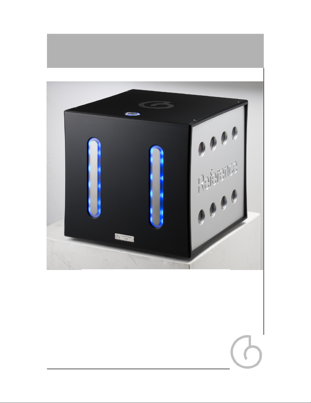
Chapter
Couplet 500M Audiophile
Power Amplifier
The exception, not the rule...
www.chapterelectronics.co.uk

Table of Contents
2
Important Safety Instructions................................... 3
Thank You from Chapter.......................................... 4
Introduction.............................................................. 5
Unpacking your Power Amplifier.............................. 6
Break In Period........................................................ 6
Installation................................................................ 7
Ventilation................................................................ 7
Operating Voltage and Mains Conditions................ 8
Power Supply Topology............................................ 8
Design Features...................................................... 9
Front Panel............................................................... 10,11,12,13
Top Panel................................................................. 14
Rear Panel................................................................ 15,16
Specifications............................................................ 17
Conformity & Acknowledgements............................. 18
Warranty Information................................................ 19
Contact Information.................................................. 19

Important Safety Instructions
Please read all instructions and precautions carefully before operating your
Chapter Couplet 500M Power Amplifier.
1 Please disconnect all items in your audio or AV system before connecting or
disconnecting any mains or interconnect cables, or when cleaning
your Chapter product.
2 Please ensure that your Chapter product is always terminated with a
three pin AC power cord. To prevent the possibility of shock all three
connections must be used.
3 To clean your Chapter product please use a soft damp cloth. Never use
flammable or combustible chemicals.
4 Never operate this product with any covers removed.
5 Never allow the inside of this unit to become wet, or pour / spill liquids
directly onto it .
6 Never block air flow through the vents on the side panels.
7 Never bypass any fuse.
8 Never replace a fuse with anything other than those specified.
9 There are no user serviceable parts within this product. If problems occur,
please contact your Chapter retailer.
10 Never expose this product to extremely high or low temperatures.
11 Unplug this product during lightning storms.
3

From all of us at Chapter...
Couplet 500M from dream to reality...
Thank you for choosing the Chapter Couplet
500M Audiophile Power Amplifier.
It has been designed and manufactured to the
highest possible standards in order
to give you many years of musical enjoyment.
4

The Chapter Couplet 500M is a ‘State Of The Art’ audiophile two-channel Power
Amplifier, that incorporates years of Research and Development in power supply
and D Class Audio circuits.
The Couplet 500M features a number of new design features along with scrupulous
attention to technical detail.
Our objective is to provide a product capable of great musicality and realism whilst
boasting exemplary technical specifications. By bringing together engineers and
designers with a lifetimes experience in audio and power system design we believe
this objective has been more than achieved.
The Chapter Couplet 500M can handle all of today’s high-resolution sources, with-
out compromising fidelity, as you would expect of any Chapter product.
Our goal, as always, is to produce a true reference quality power amplifier.
A product that can be held in the highest regard from both objective and subjective
perspectives.
After several years of research and development, we believe that we have
succeeded in fulfilling the requirements of even the most discerning audiophile.
Introduction
5

Unpacking your Power Amplifier
The shipping weight of your Chapter Couplet 500M is 25 KG.
Therefore, under normal circumstances, one person should be able to unpack the
unit safely. If you are in any doubt, please obtain the assistance of a second person.
To avoid back injury whilst carrying your amplifier (or any other piece of heavy
equipment) please crouch with a straight back and use your leg muscles.
After unpacking your power amplifier, please retain all packaging for future
transport. If you move house or you need to ship your power amplifier, only the
custom designed shipping carton is acceptable. Any other method of shipping may
result in damage and such damage is not covered under warranty.
Please inspect your power amplifier for possible damage due to shipping. If you
discover any, contact your Chapter dealer immediately.
Your Chapter Couplet 500M power amplifier will deliver excellent performance
straight out of the box, however, you should expect to hear it improve as it reaches
its normal operating temperatures and its various components ‘break-in’. In our
experience the most significant changes occur within the first 30 - 50 hours use, but
the unit will continue to improve in sound quality for about 100 hours, after which
time it remains quite consistent.
If the power is removed and reconnected to the unit, you must allow a brief ‘warm
up’ period for the unit to give off its best.
However, it is not recommended to leave your Chapter Couplet 500M power
amplifier on permanently.
Break In Period
6

Installation
Ventilation
Your Chapter Couplet 500M has been designed to fit into a good quality equipment
rack or amplifier stand. In most installations locating the power amplifier near the
loudspeakers is best.
Where permitting, locate the power amplifier near the loudspeakers and use a
longer pair of balanced interconnects to a quality pre amplifier such as a Chapter
Preface unit.
The advantage to this strategy lies in the fact that the interconnects carry low
current signals that are easily transmitted over distances with greater accuracy
than the high current signals required by loudspeakers.
Your Couplet 500M power amplifier has been designed to drive the most demanding
of loudspeakers systems which have an impedance of down to 2 ohms.
The back of your Couplet 500M power amplifier has been laid out to keep every
connection accessible. We recommend that you leave some clearance behind the
unit to fit cables without having to bend them excessively.
In order to conform with CE regulations your power amplifier is fitted with a rocker
style power switch on the rear of the unit as well as a multifunction ‘standby’ touch
sensor on the front of the unit. This rear mounted rocker switch disconnects power
from the power supply, resulting in effective disconnection of the amplifier from the
AC mains.
Please allow your power amplifier to have at least five centimetres between the top
cover and the next shelf up on an equipment rack.
The slotted vents on the side of the unit must not be obstructed, as this would
reduce the free flow of air through the unit.
7

Operating Voltage and Mains Conditions
A good quality three pin, 13 ampere IEC standard, detachable mains lead is
provided for use with your power Amplifier. It is recommended that you use this
lead. Please contact us for advice if replacement is required.
The power supply is set at the factory to work at either 110 / 110 VAC or 220/240
VAC at 50/60Hz. Please use your amplifier in regions that have the same voltage
conditions as those detailed on the back of your unit.
If you move to a country that uses a different mains voltage please consult your
distributor to arrange for your amplifier to be adjusted accordingly.
Thus total audio performance is assured anywhere in the world.
8
Power Supply Topology
Our New ‘Balanced Zero Ripple’ power supply provides the amplifier sections with
a rock steady Ppower supply rails, essential for deep articulate bass, as well as a
grain free treble performance. You will notice that even when pushed very hard the
Couplet 500M will not change is sonic presentation due to the huge demands on the
power supply.
This regulated characteristic is achieved without the use of feedback and is thus able
to react as quickly as the amplifier demands, no lag, no compensation, just an almost
limitless reserve of power that would only normally be available on a power supply
around four times the size of that found in the Couplet 500M.
Great care is take to ensure that mains bourne noise (including DC components) do
not enter the amplifier and thus compromise the amplifier performance - this filtering
and in some cases blocking ensures that the Couplet 500M is essentially silent.
Regulation and filtration are only part of the picture - a power supply must also be
low noise, and not interfer with the other delicate parts of the circuit electrically or
magnetically. It will take you only a few moments to hear that we have created an
amplifier that can deliver a deftness of touch combined with tremendous punch.

Design Features
Finest Part Selection: The Couplet 500M uses the best sounding OPAMPS from
Burr Brown. All electrolytic capacitors, are a considered combination of Samwha
and ultra low ESR Panasonic Gold series. All components used without our
power supply and amplifier design have been auditioned for both performance,
consistency and durability. At Chapter we also use the finest ‘Melf’ surface mount
precision resistors.
Balanced Zero Ripple Power Supply: This technology allows the benefits of a
regulated supply without the size, heat and wasted energy of a conventional design
The demands on the power supply rails are balanced between positive and negative
in real time to ensure lowest levels of ripple and noise to feed the amplifier circuits.
Massive Energy Storage: By combining the benefits of the Balanced Zero Ripple
supply with a large number of ultrafast high voltage capacitors we can ensure that
even the most demanding of musical passages do not peturb the voltage rails of the
amplifier, allowing for effortless reproduction of audio.
This energy storage is necessary for providing sustained deep and controlled bass.
Balanced ground layout: Cancels the ground currents that can cause
Inter-modulation distortion and crosstalk in a conventional stereo design.
Full Immersion Gold Printed Circuit Boards: Audio signals travel on gold track.
As you would imaging, compared to copper and gold plate this is a very expensive
to manufacture, but the sonic benefits are hugely tangible in terms of space, air and
dynamics.
Unique D Class amplifier circuit: Our amplifier circuitry is elegant and simple. It
employs post filter feedback and has a flat harmonic distortion characteristic across
the entire audio bandwidth. The circuit combines the best virtues of both valve and
solid state designs with unparalled dynamic range.
Touch Sensor operation: In order to give the user full control over the amplifier, a
series of touch sensors have been implemented into the unit that are subtle on the
eye, and yet easy to use. These sensors can be used to change inputs, mute the
amplifier, or change the lighting conditions on the unit.
9
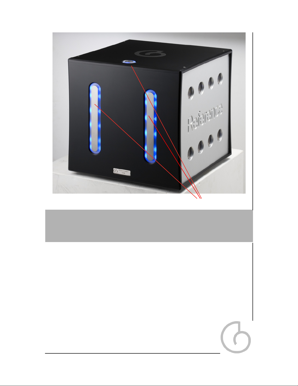
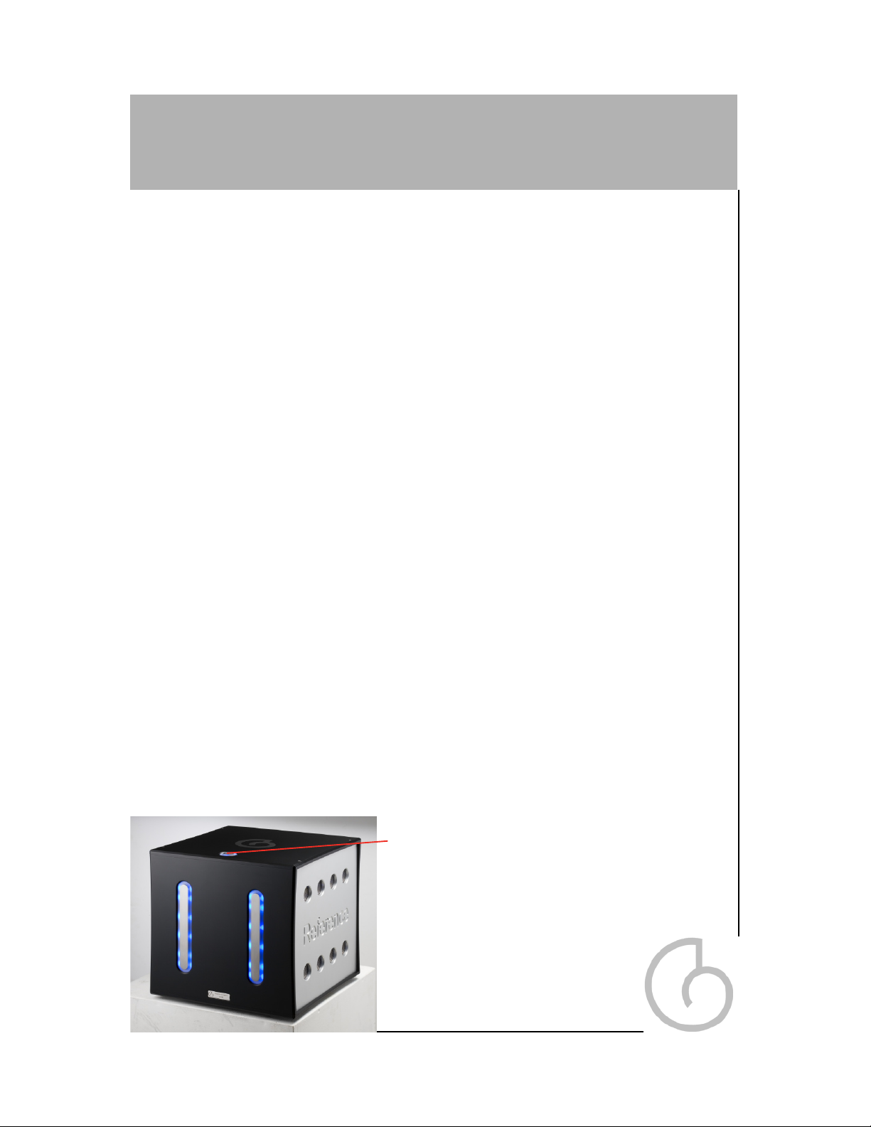
Front Panel
‘Touch sensor’ style
standby switch
1. Left touch sensor options
a. Front LED brightness control
b. Internal LED brightness control
2. Right touch sensor options
a. Input display
b. Input toggle
c. Input Earth Select
3. Standby button options
a. Mute
b. Standby
10
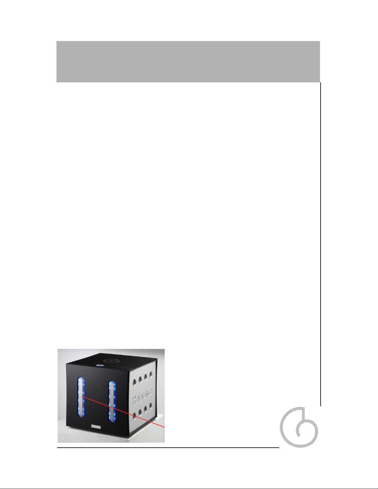
Front Panel con’t
1. Left touch sensor options
a. Front LED brightness control
To change the brightness of the front panel and standby panel blue lights, press and
hold the LEFT touch sensor strip on the front panel for 4-5 seconds until the front
panel lights start to flash
.
After the lights finish flashing, press and hold the left touch sensor strip to lower the
brightness level or press and hold the right touch sensor strip to raise the brightness
level to the desired level.
Once you are happy with the brightness level, simply wait for 5 seconds and the
front panel lights will flash again for 5 seconds to confirm the change.
b. Internal LED brightness control
To change the brightness of the internal blue lights, first put the unit into “MUTE”
mode by pressing the “STANDBY” button on the top panel for less than 1 second.
The RED lights in both front panel touch sensor strips will illuminate to indicate that
the unit is in “MUTE” mode.
Next press and hold the LEFT touch sensor strip on the front panel for 4-5 seconds
until the Internal lights start to flash.
After the lights finish flashing, press and hold the left touch sensor strip to lower the
brightness level or press and hold the right touch sensor strip to raise the brightness
level to the desired level.
Once you are happy with the brightness level, simply wait for 5 seconds and the
Internal lights will flash again for 5 seconds to confirm the change.
11
Left Touch Sensor Strip
Input
Selected
Flashing
Speed
Description
RCA Input
(Option
Recommend
ed for use
with Chapter
Product)
Fast
Gain stage input COLD connection
is connected to System 0v (AGND).
RCA Input connected between
AGND & HOT connection (AGND is
floated f rom the chassis via a
100Ohm Wire-wound resistor)
RCA Input
Slow
Gain stage input COLD floated from
System 0v (AGND) via a 100K
Impedance. RCA Input connected
between COLD & HOT connection
(AGND is f loated f rom the chassis via
a 100Ohm Wire-wound resistor)
XLR Input
(Option
Recommend
ed for use
with Chapter
Product)
Fast
Gain stage input HOT & Cold are
directly connected to XLR Pins 3 & 2
respectively. System 0v (AGND) is
connected directly to the System
Chassis GND. (AES recommended
Balanced Input Specification)
XLR Input
Slow
Gain stage input HOT & Cold are
directly connected to XLR Pins 3 & 2
respectively. System 0v (AGND) is
floated f rom the chassis via a
100Ohm Wire-wound resistor)
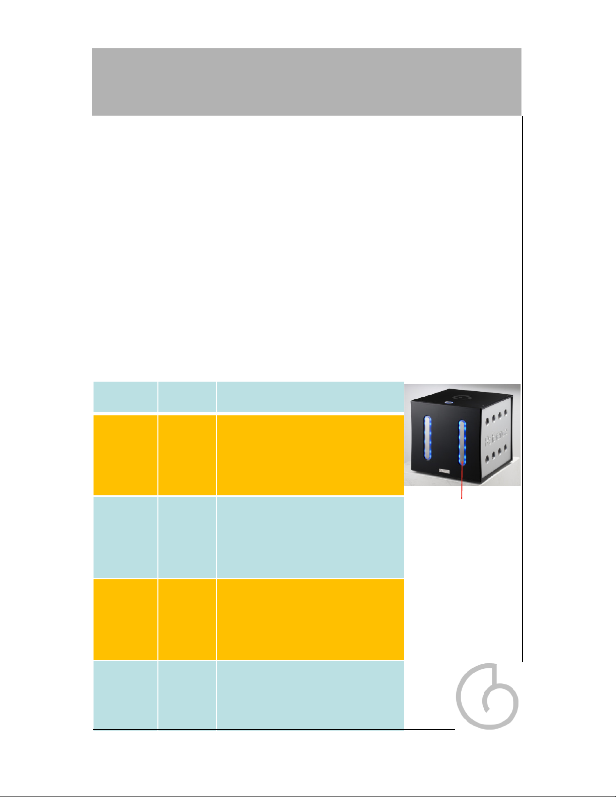
Front Panel con’t
2. Right touch sensor options
a. Input Display
You can display the currently selected input setting and Earth selection setting by
using the Right touch sensor strip. Please ensure that the unit is not in “MUTE”
mode, and that none of the front panel RED Lights are illuminated or are flashing
before starting.Press and release the Right touch sensor strip within 2 seconds, to
put the unit into “DISPLAY” mode.
Firstly, the unit will flash the RED lights associated with the selected input for five
seconds. These are LEFT touch sensor strip RED lights for RCA Input, or the
RIGHT touch sensor strip RED lights for the XLR Input.The speed of the lights flash-
ing indicates the status of the Earth select configuration according to the table oppo-
site.
After displaying the Earth selection the unit will hold the RED lights on for a further 5
seconds. During this time you can alter the Earth Selection setting using the proce-
dure shown below.
12
Right Touch Sensor
Strip

Front Panel con’t
2. Right touch sensor options
b. Input Toggle
You can toggle between the XLR and RCA inputs by using the Right touch sensor
strip.
Please ensure that the unit is not in “MUTE” mode, and that none of the front panel
RED Lights are illuminated or are flashing before starting.
Press and hold the Right touch sensor strip for at least 2 seconds, to tog-
gle between the inputs. This will change the selected input and put the unit into
“DISPLAY” mode as described above to show the new selected input and Earth
selection mode.
c. Input Earth Select
You can toggle between the Earth select modes by using the Right touch sensor
strip. Please put the unit into “DISPLAY” mode using the procedure described in
section ‘a’ above.
When the RED lights have finished flashing to show the current Earth selection set-
ting, they will stay on continuously for a further 5 seconds. During this time press
and hold the RIGHT touch sensor for 5 seconds. This will toggle the Earth selec-
tion setting, and the unit will enter “DISPLAY” mode from the start of the process as
described above.
The unit will not change the relay status until he end of display mode and will briefly
flash both front panel RED lights to confirm the change, and will then return to
“NORMAL” mode.
13
Top Panel
3. Standby button options
a. Mute
You can put the unit into “MUTE” mode by pressing the STANDBY touch sensor but-
ton for less than 2 seconds.
The unit will indicate “MUTE” status by turning on both the RIGHT and LEFT RED
lights on the units’ front panel.
b. Standby
You can enter and exit “STANDBY” mode by pressing and holding the STANDBY
touch sensor for more than 2 seconds.
Touch Sensor Operation
The Qube Reference 500M uses state of the art QPROXTM touch sensor technol-
ogy first developed by QPROXTM for the Apple iPod.
For the most reliable operation, during initial cold power on (i.e. mains power on)
and after release from “STANDBY” mode, the unit will perform a calibration of the
touch sensors to compensate for any noise in the units’ external environment (either
electrical or radiated). This may cause the sensors to become unresponsive during
this time. Please allow the calibration cycle to complete to ensure reliable operation.
If any button is pressed and held for more than 60 seconds this will also automati-
cally trigger the above calibration process.
14
Standby Touch Sensor
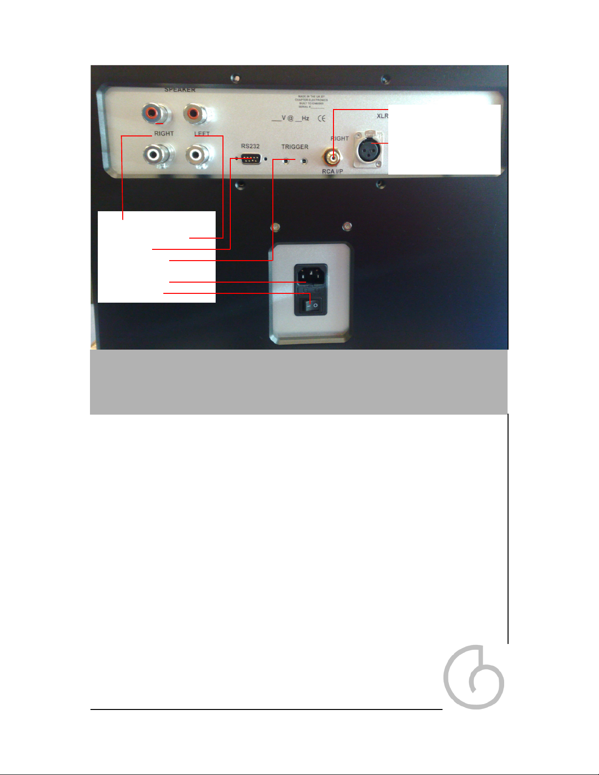
1 True Balanced Input: Accepts signals from pre amplifiers or digital
components with a variable analogue output via high quality neutrik XLR
connector. The pin assignments conform with the AES standard of pin 1
ground, pin 2 signal +, pin 3 signal - and the connector ground being chassis
ground. In order to maintain absolute phase, please check to make sure that
your pre amplifier has the same pin assignments.
2 Single-ended Input: Your Chapter Couplet 500M power amplifier can also accept
RCA single ended interconnect cables.
3 WBT 0765 Speaker Binding Posts: All Chapter Audio amplifiers are fitted
with WBT binding posts. These high current, five way, insulated connectors
are extremely well made and are the finest sounding connectors on the
market. The ‘Red’ connectors are positive and the ‘White’ connectors are negative. Ensure that the
binding posts are finger tight when connecting ‘spades’.
4 DC Trigger: The Couplet 500M is fitted with a DC trigger. This will allow for remote operation of the
unit with connected to either a 5 or 12VDC source.
5 IEC Mains Input:
Please use an earthed 3 Pin Mains lead with your Couplet 500M at all times. Ensure
the amplifier is operated at the correct mains voltage as
indicated on the back of the unit.
Rear Panel 15
Right Loudspeaker Outputs
Left Speaker Outputs
RS232 Input
DC Trigger Input
IEC Mains Input
On / Off Switch
Single Ended Input
Balanced Input

Rear Panel Continued
6 RS232 Port:
The Couplet 500M can be controlled via its RS232 control port.
A list of commands is detailed below:
#CH-CO-ON
If in Standby then exit from Standby otherwise do nothing.
#CH-CO-OFF
If not in Standby then enter Standby otherwise do nothing.
#CH-CO-RING-1..100
Set ring PWM brightness level to value specified between
1..100 and store to memory. #CH-CO-BUTTON-1..100
Set button PWM brightness level to value specified between
1..100 and store to memory.
#CH-CO-SEL_XLR
If not already selected then select XLR Input
#CH-CO-SEL_RCA
If not already selected then select RCA input.
#CH-CO-SEL_EARTHSEL_RCA-ON
. Sets EARTHSEL Relay to be connected for RCA input
#CH-CO-SEL_EARTHSEL_RCA-OFF
Sets EARTHSEL Relay to be disconnected for RCA input
#CH-CO-SEL_EARTHSEL_XLR-ON
Sets EARTHSEL Relay to be connected for XLR input
#CH-CO-SEL_EARTHSEL_XLR-OFF
Sets EARTHSEL Relay to be disconnected for XLR input
#CH-CO-MUTE
If not already muted then Mute Amplifier
#CH-CO-UNMUTE
If not un-muted then Un-Mute amplifier
CH-CO0 = Off - Turns the Couplet 500M Off remotely
CH-CO1 = On - Turns the Couplet 500M On remotely
Once a correct signal is received by the Couplet 500M, the unit will send
back the signal ‘ Chapter Couplet 200S OK’
9600 Baud, 8 Bit, 1 stop bit, no parity, No Flow Control
Please note that RS232 control takes precedence over manual control.
16

Specifications
Electrical
Output Power 500 Watts per channel 8 Ohms, both channels driven (10mS Burst 10% Duty Cycle)
1000 Watts per channel 4 Ohms, both channels driven (10mS Burst 10% Duty Cycle)
THD + N Less than 0.01% at 1KHz. 100 watts 8 ohms (using AUX0025 Filter)
Less than 0.02% at 1KHz. 100 watts 8 ohms (22Hz to 22kHz bandwidth)
IM Distortion Better than -100dB (19+20KHz dual tone test - 1 KHz product at 1V input)
Frequency response 5Hz to 65KHz +0 - 3dB
Common mode rejection ratio Better than -75dB (1kHz @ 0dBV)
Gain 26dB
Audio inputs
Impedance (unbalanced) 47K Ohms
Impedance (balanced) 94K Ohms
Audio outputs
Impedance Less 0.05 Ohms 20hz to 20KHz
Mechanical
Input sockets 1 pair of XLR for balanced line operation
1 pair of RCA Phono for single ended operation
Output sockets 2 Pairs of WBT output terminals per channel
Other Sockets DC Trigger input. RS232 connector,
Finish Fully bead blasted, anodised aluminium alloy casework.
Power on/off Switch and indicator. IEC mains input socket .
Weight Approx. 45 Kg
Size 390 x 370 x 390 mm (WxHxD) approx.
Note: Although the information given is in good faith, Chapter Electronics reserves the right to
improve specifications and details without notice.
17

Conformity
CE Declaration of Conformity
The conformity of the designated product with the provisions of Directive number 89/336/EEC
(EMC) is proved by full compliance with the following standards:
Standard number Date of Issue Test type
EN55013 1994 Conducted emissions
EN55013 1994 Absorbed emissions
EN60555-2 1987 Harmonics
EN60555-3 1987 Voltage fluctuations
EN55020 1987 Immunity
EN60065 1993 General requirements *
* to include: Components, Electrical connections and mechanical fixings, External flexible cords,
Fault conditions, Heating under normal conditions, Insulation requirements, Ionising, Marking,
mechanical strength, Parts connected to the mains supply, Shock hazards under normal operating
conditions, Terminal devices.
Chapter Electronics Ltd. also declares that this product conforms with the Low Voltage
Directive 73/23/EEC 89/336/ EEC as amended by 92/31/EEC and 93/68/EEC.
Chapter would like to thank the following organisations for their help and support in
developing this product
Our long suffering wives and famalies.......... :-)
Acknowledgements
18

Warranty Information
This product is guaranteed under the conditions that apply in the Country of
purchase. The normal guarantee runs from a period of two years from date of
purchase.
In addition to any statutory rights the customer may have, we will replace any parts
that have failed due to faulty manufacture.
Warning: Please refer all service enquiries to authorised Chapter Dealers
only. Unauthorised servicing or dismantling of the product invalidates the
manufacturer’s warranty.
If you are unsure about any aspect of obtaining service, please contact your
Chapter dealer. Should your require a list of local dealers, please contact
the Chapter offices, or your national distributor.
Please keep a copy of the sales receipt to establish the purchase date of the
product.
Please ensure that your equipment is insured by you during any transit or shipment.
Contact Information
Chapter Electronics Ltd
5 Liberty Square
Kings Hill, West Malling
Kent
ME19 4AU
United Kingdom
Notice: Each Chapter Couplet 500M Power-amplifier is unique in its manufacture. We use only the
finest suppliers with the metalwork being machined by a local ISO 9002 quality assured firm. Due to
the quality of raw material and finish style adopted for Chapter products it is possible
to see the natural alloy grain structure, giving each unit its own individual Signature.
Customers should accept and understand that there are slight differences between
units and that this is down to the natural grain in the metal.
www.chapterelectronics.co.uk
Tel: +44 (0)208 1235533
VAT Number: 758 2309 15
Company Number: 4371385
Chapter...great expectations in ‘state of the art’ audio.
19

Property of Chapter Electronics Ltd. No
unauthorised copying of this document is
permitted without written consent of the Company
Chapter Electronics Ltd 2005.
Table of contents
Other Chapter Audio Amplifier manuals


