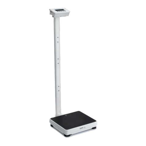
Charder MS4980 User manual

USER MANUAL
MS4980
Stand-on Floor Scale
Please keep the instruction manual at hand all the time for future reference.

2
Explanation of Text/Symbols on Device Label/Packaging
Text/Symbol
Meaning
Caution, consult accompanying documents before use
Separate collection for waste of electrical and electronic equipment, in
accordance with Directive 2002/96/EC. Do not dispose of device with
everyday waste
Name and address of device manufacturer, and year/country of manufacture
Carefully read user manual before installation and usage, and follow
instructions for use.
Medical electrical device, Type B applied part
Device catalogue number / model number
Device is a medical device. Text indicates device category type
Manufacturer's batch or lot number for device
Device's serial number
Device's Unique Device Identifier
Device conforms to Declaration of Conformity requirements
Value in mass units (verified models only). This is the difference between
two consecutive display values, used to classify and verify a scale
Device complies with EC directives (verified models only)
M: Conformity label in compliance with Directive 2014/31/EU for
non-automatic weighing instruments
22: Year in which conformity verification was performed and the CE label was
applied. (ex: 22=2022)
0122: Identifier for metrology Notified Body
Device is a Class III scale in compliance with Directive 2014/31/EU
(verified models only)
Event counter confirming how many times device has been calibrated
(if applicable)
Device's Taiwan NCC approval number
Device's type of power and voltage

3
Copyright Notice
Charder Electronic Co., Ltd.
No.103, Guozhong Rd., Dali Dist., Taichung City 41262 Taiwan
Tel: +886-4-2406 3766
Fax: +886-4-2406 5612
Website: www.chardermedical.com E-mail: info_cec@charder.com.tw
Copyright© Charder Electronic Co., Ltd. All rights reserved.
This user manual is protected by international copyright law. All content
is licensed, and usage is subject to written authorization from Charder
Electronic Co., Ltd. (hereinafter Charder) Charder is not liable for any
damage caused by a failure to adhere to requirements stated in this
manual. Charder reserves the right to correct misprints in the manual
without prior notice, and modify the exterior of the device for quality
purposes without customer consent.
Charder Electronic Co., Ltd.
No. 103, Guozhong Rd., Dali Dist.,
Taichung City, 41262 Taiwan

4
CONTENTS
I. Safety Notes .......................................................................... 5
A. General Information ............................................................ 5
B. EMC Guidance and Manufacturer's Declaration........................ 8
II. Assembly.............................................................................12
A. Column.............................................................................12
B. Using adapter and charging battery......................................12
C. Replacing Rechargeable Battery Pack ...................................13
D. Optional Accessories ..........................................................14
III. Indicator............................................................................15
A. Indicator and Key Functions ................................................15
B. Display layout....................................................................16
IV. Basic Operation ..................................................................17
A. Setup wireless data transfer ................................................17
B. Weight measurement .........................................................18
C. BMI calculation ..................................................................18
D. Tare .................................................................................19
E. Pre-Tare ............................................................................20
V. Device Setup ........................................................................23
VI. Connecting scale to receiving device ..................................24
VII. Troubleshooting ................................................................25
VIII. Product Specifications .....................................................27
IX. Declaration of Conformity ...................................................28

5
I. Safety Notes
A. General Information
Thank you for choosing this Charder Medical device. It is designed to be
easy and straightforward to operate, but if you encounter any problems
not addressed in this manual, please contact your local Charder service
partner.
Before beginning operation of the device, please read this user manual
carefully, and keep it in a safe place for reference. It contains important
instructions regarding installation, proper usage, and maintenance.
Intended Purpose
This medical device is designed to be used in accordance with national
regulations, to measure weight within specifications, for weight-related
usage by professionals.
Clinical Benefit
Measurement results can be used by professionals to monitor
weight-related issues.
General Handling
◼Device should be placed on stable, flat, solid, non-slippery surface.
◼Usage on soft surfaces (ex: carpet) may result in inaccurate results.
◼Ensure all parts are properly locked and tightened before operating
the device.
◼Device is intended to measure one subject at a time.
Safety Instructions
◼Batteries should be kept away from children. If swallowed, promptly
seek medical assistance.
◼The device has an expected service life of 5 years when correctly
handled, serviced, and periodically inspected in accordance with
manufacturer's instructions.
◼Always comply with appropriate regulations when using electrical
components under increased safety requirements.
◼Ensure voltage marked on power supply matches mains power
supply.
◼The device is intended for indoor use only.
◼Observe permissible ambient temperatures for use

6
Environmental
◼All batteries contain toxic compounds; batteries should be disposed
of via designated competent organizations. Batteries should not be
incinerated.
Cleaning
◼Device surface should be cleaned using alcohol-based wipes.
Corrosive cleansing liquids should not be used. Pressure-washers
should not be used.
◼Do not use large amounts of water when cleaning the device, as it
may cause damage to the internal electronics.
◼Always disconnect device from mains power before cleaning.
Maintenance
◼Device does not require routine maintenance. However, regular
checking of accuracy is recommended; frequency to be determined
by level of use and state of device, or local metrology/measuring
instrument regulations if applicable. If results are inaccurate, please
contact local distributor.
Warranty/Liability
◼The period of warranty shall be eighteen (18) months, beginning on
the date of purchase. Please retain your receipt as proof of purchase.
◼No responsibility shall be accepted for damage caused through any
of the following reasons: unsuitable or improper storage or use,
incorrect installation or commissioning by the owner or third parties,
natural wear and tear, changes or modifications, incorrect or
negligent handling, chemical, electrochemical, or electrical
interference.
◼All maintenance, technical inspections, and repairs should be
conducted by an authorized Charder service partner, using original
Charder accessories and spare parts. Charder is not liable for any
damages arising from improper maintenance or usage.
Disposal
◼This product is not to be treated as regular household waste, but
should be taken to a designated collection points for electronics.
Further information should be provided by local waste disposal
authorities.
Warning
◼Only the original adapter should be used with the device. Using an

7
adapter other than the one provided by Charder may cause
malfunction.
◼Do not touch the power supply with wet hands.
◼Do not crimp the power cable, and avoid sharp edges.
◼Do not overload extension cables connected to the device.
◼Route cables carefully, to avoid tripping.
◼Keep device away from liquids.
◼Do not remove the plug by yanking on the cable.
◼Use only a correctly wired (100-240VAC) outlet, and do not use a
multiple outlet extension cable.
◼Do not under any circumstances dismantle or alter the device, as this
could result in electric shock or injury as well as adversely affect the
precision of measurements.
◼Do not place the device in direct sunlight, or in close proximity to an
intense heat source. Excessively high temperatures may damage the
internal electronics.
Incident Reporting
◼Any serious incident that has occurred in relation to the device
should be reported to the manufacturer, EU representative (if device
is used in EU member state), and competent authority of
user/subject's member state

8
B. EMC Guidance and Manufacturer's Declaration
Guidance and manufacturer’s declaration-electromagnetic emissions
The MS4980 Stand-on Floor Scale is intended for use in the electromagnetic environment
specified below. The customer or the user of the device should assure that it is used in such
an environment.
Emission test
Compliance
Electromagnetic
environment-guidance
RF emissions CISPR 11
Group 1
The device uses RF energy only for
its internal function. Therefore, its
RF emissions are very low and are
not likely to cause any interference
in nearby electronic equipment.
RF emissions CISPR 11
Class B
The device is suitable for use in all
establishments, including domestic
establishments and those directly
connected to the public low-voltage
power supply network that supplies
buildings used for domestic
purposes.
Harmonic emissions IEC
61000-3-2
Class A
Voltage fluctuations /flicker
emissions IEC 61000-3-3
Compliance
Guidance and manufacturer’s declaration-electromagnetic immunity
The MS4980 Stand-on Floor Scale is intended for use in the electromagnetic environment
specified below. The customer or the user of the device should assure that it is used in such
an environment.
Immunity test
IEC 60601
test level
Compliance
level
Electromagnetic
environment-guidance
Electrostatic
discharge(ESD)
IEC 61000-4-2
±8 kV contact
±2 kV, ± 4 kV,
± 8 kV, ± 15 kV
air
±8 kV contact
±2 kV, ± 4 kV,
± 8 kV, ± 15 kV
air
Floors should be wood, concrete
or ceramic tile. If floors are
covered with synthetic material,
the relative humidity should be
at least 30%

9
Electrical fast
transient/burst
IEC 61000-4-4
± 2kV for
power supply
lines
+ 1kV for
input/output
lines
+ 2kV for power
supply lines
+ 1kV for
input/output
lines
Mains power quality should be
that of a typical commercial or
hospital environment.
Surge IEC
61000-4-5
± 1kV line(s) to
line(s)
± 2kV line(s) to
earth
+ 1kV line(s) to
line(s)
+ 2kV line(s) to
earth
Mains power quality should be
that of a typical commercial or
hospital environment.
Voltage Dips,
short interruptions
and voltage
variations on
power supply
input lines IEC
61000-4-11
0% UT for 0,5
cycle
0% UT for 1
cycle
70% UT(30%
dip in UT) for
25 cycles
0% UT for 5 s
0% UT for 0,5
cycle
0% UT for 1
cycle
70% UT(30%
dip in UT) for 25
cycles
0% UT for 5 s
Mains power quality should be
that of a typical commercial or
hospital environment. If the
user of the device requires
continued operation during
power mains interruptions, it is
recommended that the device
be powered from an
uninterruptible power supply or
a battery.
Power
frequency(50/60
Hz) magnetic field
IEC 61000-4-8
30 A/m
30 A/m
The device power frequency
magnetic fields should be at
levels characteristic of a typical
location in a typical commercial
or hospital environment.
NOTE UT is the a.c. mains voltage prior to application of the test level.
Guidance and manufacturer’s declaration-electromagnetic immunity
The MS4980 Stand-on Floor Scale is intended for use in the electromagnetic environment
specified below. The customer or the user of the device should assure that is used in such an
environment.
Immunity test
IEC 60601 test
level
Compliance
level
Electromagnetic
environment-guidance
Conducted RF
IEC 61000-4-6
Radiated RF IEC
61000-4-3
3 Vrms
150 KHz to 80 MHz
6 V in ISM bands
between 0,15 MHz
and 80 MHz
80 % AM at 1 kHz
3 V/m
3 Vrms
150 KHz to 80
MHz
6 V in ISM
bands between
0,15 MHz and
80 MHz
80 % AM at 1
Portable and mobile RF
communications equipment
should be used no closer to any
part of the device including
cables, than the recommended
separation distance calculated
from the equation applicable to

10
80MHz to 2,7 GHz
kHz
3 V/m
80MHz to 2,7
GHz
the frequency of the
transmitter.
Recommended separation
distance:
d = 1,2 √P
d = 1,2 √P 80MHz to 800 MHz
d = 2,3 √P 800MHz to 2,5 GHz
Where P is the maximum output
power rating of the transmitter
in watts (W) according to the
transmitter manufacturer and d
is the recommended separation
distance in metres (m).
Field strengths from fixed RF
transmitters, as determined by
an electromagnetic site surveya,
should be less than the
compliance level in each
frequency rangeb.
Interference may occur in the
vicinity of equipment marked
with the following symbol:
NOTE1 At 80 MHz and 800 MHz, the higher frequency range applies.
NOTE2 These guidelines may not apply in all situations. Electromagnetic propagation is
affected by absorption and reflection from structures, objects and people.
a Field strengths from fixed transmitters, such as base stations for radio (cellular/cordless)
telephones and land mobile radios, amateur radio, AM and FM radio broadcast and TV
broadcast cannot be predicted theoretically with accuracy. To assess the electromagnetic
environment due to fixed RF transmitters, an electromagnetic site survey should be
considered. If the measured field strength in the location in which the device is used
exceeds the applicable RF compliance level above, the device should be observed to
verify normal operation. If abnormal performance is observed, additional measures may
be necessary, such as re-orienting or relocating the device.
b Over the frequency range 150 kHz to 80 MHz, field strengths should be less than 3 V/m.

11
Recommended separation distance between portable and mobile RF
communications equipment and the MS4980 Stand-on Floor Scale
The device is intended for use in an electromagnetic environment in which radiated RF
disturbances are controlled. The customer or the user of the device can help prevent
electromagnetic interference by maintaining a minimum distance between portable and
mobile RF communications equipment (transmitters) and the device as recommended
below, according to the maximum output power of the communications equipment.
Rated maximum
output power of
transmitter
W
Separation distance according to frequency of
transmitter m
150 kHz to 80
MHz
d =1,2√P
80 MHz to 800
MHz
d =1,2√P
800 MHz to 2,5
GHz
d =2,3√P
0,01
0,12
0,12
0,23
0,1
0,38
0,38
0,73
1
1,2
1,2
2,3
10
3,8
3,8
7,3
100
12
12
23
For transmitters rated at a maximum output power not listed above, the recommended
separation distance d in metres (m) can be estimated using the equation applicable to the
frequency of the transmitter, where p is the maximum output power rating of the
transmitter in watts (W) according to the transmitter manufacturer.
NOTE1 At 80 MHz and 800 MHz, the separation distance for the higher frequency range
applies.
NOTE2 These guidelines may not apply in all situations. Electromagnetic propagation is
affected by absorption and reflection from structures, objects and people.

12
II. Assembly
A. Column
Fasten and tighten four screws at the bottom of the base. Ensure four
adjustable feet and stability foot are at same level before using device.
B. Using adapter and charging battery
The rechargeable battery should be recharged at least once every 3
months, regardless of if the device has been used. Battery can be
charged by plugging device's exclusive adapter into AC Connector Port.
After a long period in storage (e.g. >3 months), the battery should run a
full cycle (charge/discharge) to allow it to restore full capacity.
Ensure rechargeable battery housing is installed and inserted properly
into the compartment.
If prompt displays on the LCD, please charge battery promptly to
avoid battery damage.
AC Connector Port
Four screws

13
C. Replacing Rechargeable Battery Pack
1. Open battery housing cover
2. Remove battery pack housing from indicator
3. Place new battery pack into housing, and insert into indicator

14
6. Close battery housing compartment cover. Turn on power to confirm
that battery is correctly installed.
D. Optional Accessories
This device is compatible with a variety of accessories. Please consult
their respective user manuals for assembly instructions:
a. Height Stadiometer
◼HM130D Digital Height Stadiometer
◼HM200D Digital Height Stadiometer
◼HM200U Ultrasonic Height Stadiometer
◼HM201D Digital Height Stadiometer
◼HM201M Mechanical Height Stadiometer
b. Barcode Scanner
◼AS-9300 Infrared Barcode Scanner

15
III. Indicator
A. Indicator and Key Functions
Key Function
1. POWER: Power on or power off.
2. TARE/ZERO: Reset display to 0.0 kg display. Press and hold for 6
seconds to enter device settings.
3. HOLD: Determine stable weighing value - used when weight is
unstable.
4. MEMORY: Save pre-tare values (up to 10 sets can be stored in
device memory)
5. BMI: Calculation of Body Mass Index
6. PRE-TARE: Pre-tare the known weight of an object (ex: chair)
before beginning measurement.
1
3
5
2
4
6

16
B. Display layout
Definitions
Quantity of data awaiting transfer: If device is not connected
wirelessly, measurement results will be temporarily stored in device.
Once device is connected, operator can press Transfer to send results
wirelessly. After transfer is complete, number will revert to "0"
PRE-TARE: If Pre-Tare function is active, this indicates which pre-tare
value is being used.
HOLD: Will appear if Hold is active. (Hold needs to be activated in order
to save and transfer results)
SCAN: Will appear if compatible barcode scanner is plugged into device
Transfer: After measurement is completed, height/weight result can be
transferred wirelessly (if Hold is active). Press [Transfer] to send
results.
Wi-Fi: Indicator will reflect current Wi-Fi connectivity status.
disconnected connected
Patient ID
Information
Quantity of
data
awaiting
transfer
Wi-Fi
Battery
status
Nurse ID
Transfer
key
PRE-TARE
HOLD
Scanner
Stable
Weight
Zero
Unit
Net
BMI
Height
Capacit
y
Graduation

17
IV. Basic Operation
1. Switch on the device using key. The device will automatically
perform self-calibration
2. Once "0.0" appears on indicator, device is ready for use
NOTE: If "0.0" does not display on indicator, press [TARE/ZERO] key to
zero the device.
A. Setup wireless data transfer
Direct Wi-Fi data transfer
NOTE: If results do not need to be
transferred after measurement, this
step can be skipped.
1. The device acts as an Access Point
that can be connected to via Wi-Fi. To
ensure that the phone/tablet/PC
connects to the correct device, first
identify the device's MAC Address by clicking
2. The "name" of the device's Wi-Fi Access Point will be "DP4800_(MAC
Address)" The default password to connect to the device is "00000000"
NOTE: The Model No. displayed in Information will vary depending on the
device model.

18
3. After the phone/tablet/PC is connected to the device, the wireless
symbol will change from to
4. Device is now ready to send results wirelessly to phone/tablet/PC.
5. Before or after measurement, press the [HOLD] key. "HOLD" will be
displayed on the indicator. If HOLD is not active, results cannot be
transferred.
NOTE: by default, patient ID, weight, and height must be filled in to
transfer results. Otherwise, [Transfer] button will not appear. To allow
transfer of "incomplete" results, please change settings (press and hold
[TARE/ZERO] key for 6 seconds to enter settings).
B. Weight measurement
1. Guide subject to stand upon the measurement platform. After a few
seconds, the average weight will be displayed on the indicator. This
weight will be locked - at this point, subject can step off from device.
2. If BMI calculation is unnecessary, press [Transfer] button to send
results wirelessly. If device is not currently connected, results will
temporarily be stored in device memory (number of records saved
indicated by 'Awaiting transfer'). After transfer is complete, number will
revert to "0"
C. BMI calculation
Manual Input
1.Press the [BMI] key to enter BMI mode.
2. Enter height using numeral keys (ex: to input 170 cm, press 1-7-0-0).
Press [CLEAR] key to re-input.
3. After inputting height, press [Enter] to confirm.

19
4. Proceed to weigh subject as usual. Indicator will display weight, height,
and BMI.
5. To transfer results, ensure that HOLD is active, and press [Transfer]
button to send results wirelessly. If device is not currently connected,
results will temporarily be stored in device memory (number of records
saved indicated by 'Awaiting transfer'). After transfer is complete,
number will revert to "0"
With attached Height Stadiometer
1. Ensure compatible Charder digital height stadiometer is plugged into
indicator. If stadiometer is plugged in, manual height input will be
disabled.
2. Proceed to weigh subject as usual. Adjust head stopper of attached
stadiometer accordingly. (HM200U Ultrasonic Height Stadiometer will
automatically measure height) Indicator will display weight, height, and
BMI.
3. To transfer results, ensure that HOLD is active, and press [Transfer]
button to send results wirelessly. If device is not currently connected,
results will temporarily be stored in device memory (number of records
saved indicated by 'Awaiting transfer'). After transfer is complete,
number will revert to "0"
Category
BMI (kg/m2)
Risk of obesity-related disease
Under
< 18.5
Low
Normal
18.5-24.9
Average
Over
24.9-29.9
Slightly Increased
Obese I
30.0-34.9
Increased
Obese II
35.0-39.9
High
Obese III
> 40
Very High
(World Health Organization adult BMI standards)
D. Tare
The tare function allows the user to deduct the weight of objects from the
device's measurement result.
1. Place object that needs to be tared onto measurement platform.
2. Press [TARE/ZERO] key after stable symbol appears on indicator.
Display will indicate "0.0".
3. Guide subject (plus tared object) to be weighed upon measurement
platform. Conduct measurement.
4. To clear tare value, remove all objects from measurement platform,
and press [TARE/ZERO] key.

20
E. Pre-Tare
The Pre-Tare function is used to subtract the known weight of a
substance prior to weighing. The device can store 10 sets of pre-tare
values in memory. Once pre-tare weights have been stored, they can be
recalled by pressing the [MEMORY] key.
Input Pre-Tare Value
DESCRIPTION
EXAMPLE
Press [PRE-TARE] key. Input
pre-tare weight value, starting
from the left
Enter pre-tare weight using 0~9
keys.
Ex: to pre-tare 5.0 kg of weight,
press 0-0-5-0.
Ex: to pre-tare 13.5 kg of weight,
press 0-1-3-5.
Press [Enter] key to confirm the
pre-tare weight.
Table of contents
Other Charder Scale manuals

Charder
Charder Z420 User manual
Charder
Charder MS5461 User manual
Charder
Charder MS6001 User manual
Charder
Charder R220+ User manual
Charder
Charder MS 2400 User manual

Charder
Charder MS 2100 User manual
Charder
Charder MS2510 Manual
Charder
Charder MS-6121R User manual
Charder
Charder MS-3500 User manual
Charder
Charder MS2500 Use and care manual
Charder
Charder MS3400 User manual
Charder
Charder DP3700 User manual
Charder
Charder MS5810 User manual

Charder
Charder MS5810 User manual

Charder
Charder MS 2400 User manual
Charder
Charder MS5750 User manual
Charder
Charder MS4900 User manual
Charder
Charder MS7321 User manual
Charder
Charder MS4400 User manual
Charder
Charder W320 User manual
