Charger SP Series Owner's manual

Water Specialist
SP Solar Powered Control Valve
Programming Manual

Page 2 SP Manual

SP Manual Page 3
Table of Contents
Front Cover and Drive Assembly ............................................................................................................... 4
Wiring Diagram .......................................................................................................................................... 5
Regeneration and Error Screens, Button Operation and Function, Regeneration Cycles and Times......... 6
User Displays.............................................................................................................................................. 7
Configuration Settings ................................................................................................................................ 8
OEM Softener System Setup .................................................................................................................... 10
Setting Options Table ............................................................................................................................... 12
OEM Filter System Setup......................................................................................................................... 13
Installer Display Settings .......................................................................................................................... 14
Diagnostics ............................................................................................................................................... 15
Battery Diagnostics ................................................................................................................................... 17

Page 4 SP Manual
Drawing No. Order No. Description Quantity
1 V3175SP-01 WS1SP FRONT COVER ASSEMBLY 1
2 V3107-01 WS1 MOTOR 1
3 V3814-01 WS1 DRIVE BRACKET SOLAR & SPRING CLIP 1
4 V4072SP-03BOARD WS1THRU SPPCB AC/DC REPL 1
5 V3110 WS1 DRIVE GEAR 12X36 3
6 V3109 WS1 DRIVE GEAR COVER 1
7 V3835-02 WS1SP BATTERY PACK CHARGED W/TIE 1
8 V3842 WS1SP SOLAR PANEL W/BRKT ASY 1
Not Shown V3186-06 WS1 POWER SUPPLY US 15VDC HOCP 1
Not Shown V3178 WS1 DRIVE BACK PLATE 1
Front Cover and Drive Assembly
Refer to Control Valve Service Manual for other drawings and part numbers.
Power Supply U.S. International
Supply Voltage 100-120VAC 100-240 VAC
Supply Frequency 50/60 Hz 50/60 Hz
Output Voltage 15 VDC 15 VDC
Output Current 500 mA 500 mA
4
6
5
3
2
UseCableTietosecurebattery
pack to drive bracket when
replacing V3835-02.
Valves shipped with battery not connected to
circuitboard.Connectthisendtocircuitboard.
7
Battery replacement
is 3 volt lithium coin
cell type 2032.
Correct
Battery
Orientation
Battery Fully Seated
When replacing the battery, align
positives and push down to fully seat.
8
1
Battery
Connections
Power
Supply
Connectredwirefrom
solar panel to “+”
terminal, and black
wire to “-” terminal.

SP Manual Page 5
Wiring Diagram

Page 6 SP Manual
Range
Cycle Softening Filtering Regen Filtering
Backwash
Backwash
Regenerant Draw/Slow Rinse (UP or DN)
Fast Rinse
Regenerant Refill
RegenerantRefill2.0or1.5settoMIN(softeningonly)
Service
1-120 minutes
1-180 minutes
1-120 minutes
0.1-200.0 lbs.
0.1-99.0minutes
1-480 minutes
1-120 minutes
1-180 minutes
1-120 minutes
.05-20.0 Gal.
0.1-99.0minutes
NA
1-120 min.
NA
1-120 min.
NA
NA
NA
Regeneration and Error Screens
Theusercaninitiatemanualregeneration.Theuserhastheoptiontorequestthemanualregenerationatthedelayedregeneration
time or to have the regeneration occur immediately:
1.PressingandreleasingtheREGENbutton.“
REGENTODAY”willflashonthedisplayandtheregenerationwilloccuratthe
delayed regeneration time. The user can cancel the request by pressing and releasing the REGEN button.
2.PressingandholdingtheREGENbuttonforapproximately3secondswillimmediatelystarttheregeneration.Theusercannot
cancel this request, except by resetting the control by pressing NEXT and REGEN simultaneously for 3 seconds.
Regeneration Cycles and Times
Button Operation and Function
Changes variable being displayed.
Pressing once and releasing will schedule a regeneration at the preset delayed regeneration time.
Pressing again and releasing will cancel the regeneration.
Pressing and holding for 3 seconds will initiate an immediate regeneration
Pressing while in regeneration will advance to the next cycle.
Pressing in the program levels will go backwards to the previous screen
Key sequence to lock and unlock program settings.
Scrolls to the next display.
Holdingfor3secondsinitiatesacontrolreset.Thesoftwareversionisdisplayedandthepistonreturns
to the home/service position, resynchronizing the valve.
Usedwithvalvetype1.0 ,holdingforatleast3secondscausesaswitchinthetankinServicewithoutcycling
theregenerationvalve. Aftertankswitch,daysremainingandcapacityremainingstatusisretainedforeach
tank until the next regeneration.
Regen Screen
Displays the time remaining in the current cycle. Pressing REGEN advances to the next cycle.
Error Screen
Alternated flashing Err and error code every 3 seconds. Clear by disconnecting
the power supply at the PC board and reconnecting, or press NEXT and
REGEN simultaneously for 3 seconds.
In Alternator Systems when a unit is waiting to initiate the first cycle step of regeneration,
“REGEN Pndg” is displayed.
“STbY” is displayed in Alternator Systems when a valve is in Standby state.
If 1.5 or 2.0 is selected in Step 2CS, cycles can be set to “oFF”.

SP Manual Page 7
User 3
Flow Rate.
Displays present flow rate.
Not viewed (along with SOFTENING or FILTERING Icon) if ALT A or ALT b is set
in CONFIGURATION 4 and the valve is currently in Standby. When 1.0T is set in
CONFIGURATION 1, the display will indicate the tank currently in Service (“A” or “b”) in
the leftmost digit.
User 1
Typical user display. Shows volume remaining to regeneration. This screen will not be
viewed if the control is set for time-clock operation.
User 2
Displays number of days to next regeneration. Only displayed if control is set for time-clock
operation.
User 4
Displays total volume in gallons since last reset. If a meter is not used this display will be
shown but 0 will be displayed.
PRESS FOR 3 SECONDS TO RESET TO 0.
User 5
Shows current time. When FILL is displayed, the battery pack is being charged.
Setting Time of Day
Push NEXT until time of day screen is displayed. Press and hold until SET TIME is
displayed and the hour flashes once. Press or until the correct hour is displayed.
Then press NEXT. The minutes will flash. Press or until the correct minute is displayed.
Press NEXT to return to the User Displays. Time of day should only need to be set after
power outages lasting more than 8 hours, if the battery has been depleted and a power outage
occurs, or when daylight saving time begins or ends. If a power outage lasting more than 8
hours occurs, the time of day will flash on and off which indicates the time of day should be
reset. If a power outage lasts less than 8 hours and the time of day flashes on and off, the time
of day should be reset and the battery replaced.
User Displays
General Operation When the system is operating, one of five displays may be shown. Pressing NEXT will
alternate between the displays shown below.

Page 8 SP Manual
Conguration Settings
Step 1CS – Press NEXT and simultaneously for 5 seconds and release. Press NEXT and
simultaneouslyfor5secondsandrelease.IfthescreeninStep2CSdoesnotappear,thelockonthevalveis
activated.Tounlock,press,NEXT,andREGENinsequence,thenpressNEXTandsimultaneously
for 5 seconds and release. Press NEXT and simultaneously for 5 seconds and release.
Step 1CS
Step 2CS – Use or to select 1.0 for 1” valve, 1.25 for 1.25” valve, 1.5 for 1.5” valve, 2.0 for 2” valve
or 1.0T for twin valve. Press NEXT to go to Step 3CS. Press REGEN to exit Configuration Settings.
Step 2CS
Step3CS– If1.5 or 2.0isselected in Step2CS,an additionalscreenwill
appear. It is used to select which size flow meter is to be used with the
valve,1.0r,1.5, 2.0 or 3.0. Variable meterpulsesof0.1-150.0PPG can
alsobeselected.PressNEXTtogotoStep4CS.PressREGENtoreturn
to the previous step.
Step 3CS
Step 4CS Step 4CS – Selecting the use of an outside signal to initiate a regeneration: Selection only matters if a
connectionismadetothetwopinconnectorlabeledDPSWITCHlocatedontheprintedcircuitboard.
Following is an explanation of the options:
oFF - feature not used
NOTE:InatwinalternatingsystemeachcontrolmusthaveaseparatedPsignalordPswitch.OnedPsignal
or one dP switch cannot be used for both controls.
on0–IfthedPswitchisclosedforanaccumulativetimeof2minutesaregenerationwillbesignaledtothe
unit.InatwinalternatingsystemtheMAVwilltransitionfirsttoswitchunitssothatthesignaledunitcan
startregeneration.AftertheMAVhasfullytransitioned,theregenerationbeginsimmediately.Note:For
WS1–WS1.5controlvalvesprogrammedfortwinalternating:ifthedPfunction“on0”isset,theDelayed
Rinse and Fill feature is not available.
dEL – If the dP switch is closed for an accumulative time of 2 minutes a regeneration will occur at the
scheduled delayed regeneration time. In a twin alternating system once the dP switch is triggered the
PC Board will display “REGEN TODAY” and when the delayed regen time comes the control will
switchtanksandthetriggeredunitwillthengointoregeneration.Note:ForWS1–WS1.5controlvalves
programmedfortwinalternating:ifthedPfunction“dEL”isset,theDelayedRinseandFillfeatureisnot
available.
HoLd – If the dP switch is closed a regeneration will be prevented from occurring while there is switch
closure.Inatwin alternatingsystemtheregenerationofaunitcanbepreventeduponswitchclosure.Ifthe
unitdepletesthecapacitydowntozero,itwillnotbeallowedtoswitchtankstoregenerateuntiltheswitch
isopen.Note:ForWS1–WS1.5controlvalvesprogrammedfortwinalternatingtheDelayedRinseand
Fill feature can be set.
Press NEXT to go to Step 5CS. Press REGEN to return to previous step.

SP Manual Page 9
Step 5CS – This display will not appear if 1.0T was selected in Step
2CS. Allows selection of one of the following using or :
• the Control Valve to have no hard water bypass; or
•theControlValvetohaveaseparatesourceduringtheregeneration
cycle.
Select OFF when none of these features are used.
Only use Clack No Hard Water Bypass Valves or Clack Motorized
AlternatingValves(MAV)withtheseselections.ClackNoHardWaterBypassValves(1”or1.25”V3070FForV3070FM)arenotdesignedto
be used with the alternator or separate source functions.
Conguring the Control Valve for No Hard Water Bypass Operation:
SelectnHbPforcontroloperation.Fornohardwaterbypassoperationthethreewirecommunicationcable
is not used.
SelectionrequiresthataconnectiontoMAVoraClackNoHardWaterBypassValveismadetothetwo
pinconnectorlabeledMAVlocatedontheprintedcircuitboard.IfusingaMAV,theAportoftheMAV
mustbepluggedandthevalveoutletconnectedtotheBport.WhensettonHbPtheMAVwillbedriven
closedbeforethefirstregenerationcyclethatisnotFILLorSOFTENINGorFILTERING,andbedriven
open after the last regeneration cycle that is not FILL.
NOTE:Ifthecontrolvalveentersintoanerrorstateduringregenerationmode,thenohardwaterbypass
valve will return to the open Position, if not already there.
Conguring the Control Valve for Separate Source Operation:
SelectSEPSforcontroloperation.Forseparatesourceoperationthethreewirecommunicationcableisnot
used.
SelectionrequiresthataconnectiontoaClackMotorizedAlternatorValve(MAV)ismadetothetwopin
connectorlabeledMAVlocatedontheprintedcircuitboard.TheCportoftheMAVmustbeconnectedto
thevalveinletandtheAportconnectedtotheseparatesourceusedduringregeneration.TheBportmust
be connected to the feed water supply.
WhensettoSEPStheMAVwillbedrivenclosedbeforethefirstregenerationcycle,andbedrivenopen
after the last regeneration cycle.
NOTE:Ifthecontrolvalveentersintoanerrorstateduringregenerationmode,theMAVwillreturntothe
open position, if not already there.
Step 5CS
1.0T Valve
With1.0Tset,adisplaywillallowtheusertosettheamountofpre-servicerinsetimeforthestandby
tank just prior to returning to service. Set to oFF to deactivate this feature.
EXIT TO DISPLAY SCREENS
Step 6CS Step 6CS – Fill Units: If set as a softener, if Step 2CS is set to 1.5, and FILL is part of the Regeneration
Cycle Sequence, FILL UNITS of MIN or LBS can be selected. Press
NEXT to exit OEM Configuration Setup. Press REGEN to return to
previous step.

Page 10 SP Manual
OEM Softener System Setup
Step 1S - Press NEXT and simultaneously for 5 seconds and release. If screen in Step 2S does not
appear, the lock on valve programming has been activated. To unlock press , NEXT, , REGEN in
sequence, then press NEXT and simultaneously for 5 seconds and release.
Step2S– Choose SOFTENING using or . Press NEXT to go to Step 3S. Press REGEN to exit OEM
Softener System Setup.
Step 2S
Step 1S
Step 3S – Choose Brining Direction using or . This screen is not viewed when Step 2S is set to
Filtering. Press NEXT to go to Step 4S. Press REGEN to return to previous step.
Step 3S
Step 4S – Set Refill location using or :
• “PoST” to refill the brine tank after the final rinse; or
• “PrE” to refill the brine tank four hours before the regeneration time set.
This screen is not viewed when Step 2S is set to Filtering.
Press NEXT to go to Step 5S. Press REGEN to return to previous step.
Step 4S
Step 5S – Select the time for the first cycle using or . For valve types 1.5 and 2.0, “oFF” is also
available.
Press NEXT to go to Step 6S. Press REGEN to return to previous step.
Step 5S
Step 6S – Select the time for the second cycle using or . For valve types 1.5 and 2.0, “oFF” is also
available.
NOTE: The display will alternate between the time and brine direction (UP or dn).
Press NEXT to go to Step 7S. Press REGEN to return to previous step.
Step 6S
Step 7S – Select the time for the third cycle using or . For valve types 1.5 and 2.0, “oFF” is also
available.
Press NEXT to go to Step 8S. Press REGEN to return to previous step.
Step 7S
Step 8S – Select the time for the fourth cycle using or . For valve types 1.5 and 2.0, “oFF” is also
available.
Press NEXT to go to Step 9S. Press REGEN to return to previous step.
Step 8S

SP Manual Page 11
Step 10S – Set System Capacity using or . The System Capacity setting should be based on the
volumeofresinandLBSofsaltfillsetinStep9S. PressNEXTtogotoStep11S.PressREGENtoreturn
to previous step.
Step 11S – Set Volume Capacity using or . If value is set to:
•“AUTO”capacitywillbeautomaticallycalculatedandreservecapacitywillbeautomaticallyestimated;
•“oFF”regenerationwillbetriggeredbythedayoverridesetting,orcanbesettoregenerateonspecific
days of the week.
• a number, regeneration will be triggered by the value specified (in Gallons).
If“oFF”oravolumeisused,thehardnessdisplaywillnotbeallowedtobesetinInstallerDisplaySettings
Step2I.SeeSettingOptionsTableformoredetail.PressNEXTtogotoStep12S.PressREGENtoreturn
to previous step.
Step 12S – Set Regeneration Time Options using or . NOTE: This step will not appear if Step 11S is
set to oFF or Step 5CS is set to “SYS”.
If value is set to:
• “NORMAL” means regeneration will occur at the preset time;
• “on 0” means regeneration will occur immediately when the volume capacity reaches 0 (zero); or
• “NORMAL + on 0” means regeneration will occur at one of the following:
— the preset time when the volume capacity falls below the reserve or the specified number of days
between regenerations is reached whichever comes first; or
— immediately after 10 minutes of no water usage when the volume capacity reaches 0 (zero).
“on 0” is the default if Step 2CS is set to 1.0T , and “NORMAL + on 0” is not available.
SeeSettingOptionsTableformoredetail.PressNEXTtoexitSoftenerSystemSetup.PressREGENto
return to previous step.
Step 10S
Step 11S
Step 12S
Step 9S – Select the pounds for the fifth cycle using or . For valve types 1.5 and 2.0, “oFF” is also
available.
NOTE: if Step 2CS is set to 2.0 or Step 6CS is set to MIN, Fill will be in minutes.
Press NEXT to go to Step 10S. Press REGEN to return to previous step.
Step 9S
EXIT OEM
SOFTENER
SYSTEM SETUP

Page 12 SP Manual
1Reserve Capacity estimate is based on history of water usage. Reserve Capacity estimate is not available with Twin Tank Valve.
System Type Regeneration
Option
Regeneration
Type Day Override
Softening Auto Delayed 1-28 days
Regeneration occurs at the next regeneration time when
volume capacity falls below the reserve capacity, or the
specied number of days is reached, whichever comes rst.
Softening Auto Delayed OFF Regeneration occurs at the next regeneration time when
volume capacity falls below the reserve capacity.
Softening or
Filtering
20 – 1,500,000
Gallons Delayed 1-28 days
Regeneration occurs at the next regeneration time when
volume capacity reaches 0, or the specied number of days is
reached, whichever comes rst.
Softening or
Filtering
20 – 1,500,000
Gallons Delayed OFF Regeneration occurs at the next regeneration time when
volume capacity reaches 0.
Softening or
Filtering OFF Delayed 1-28 days
Time Clock operation.
Regeneration occurs at the next regeneration time the
specied number of days is reached.
Softening
Auto or
20 – 1,500,000
Gallons
Immediate 1-28 days
Regeneration occurs immediately when volume capacity
reaches 0, or the specied number of days is reached,
whichever comes rst.
Softening or
Filtering
20-1,500,000
Gallons Immediate OFF Regeneration occurs immediately when volume capacity
reaches 0.
Softening Auto Delay + Immediate 1-28 days
Regeneration occurs at the next regeneration time when
volume capacity falls below the reserve capacity, or the
specied number of days is reached, or regeneration occurs
after 10 minutes of no water usage when volume capacity
reaches 0.
Softening or
Filtering
20 – 1,500,000
Gallons Delay + Immediate 1-28 days
Regeneration occurs at the next regeneration time the
specied number of days is reached or regeneration occurs
after 10 minutes of no water usage when volume capacity
reaches 0.
Softening Auto Delay + Immediate OFF
Regeneration occurs at the next regeneration time when
volume capacity falls below the reserve capacity, or
regeneration occurs after 10 minutes of no water usage when
volume capacity reaches 0.
Setting Options Table1

SP Manual Page 13
OEM Filter System Setup
Cycle Sequence, Adjustable Default Times (minutes)
Type Backwash Draw Backwash Rinse Backwash* Fill
Filtering Backwash 8 4
Filtering Regen 8 60 8 8 0:30 .95 GAL
FilteringRegen(2.0”) 8 60 8 8 0:30 6
*Cycle is non-adjustable, not shown in cycle sequence programming.
Step 1F - Press NEXT and simultaneously for 5 seconds and release. If screen in Step 2CS does not
appear, the lock on the valve is activated. To unlock press , NEXT, , REGEN in sequence, then press
NEXT and simultaneously for 5 seconds and release.
Step 1F
Step2F– Choose FILTERING BACKWASH or FILTERING REGEN (see table) using or . Press
NEXT to go to Step 3F. Press REGEN to exit OEM Filter System Setup.
Step 2F
Step 3F – Select the time for the first cycle using or .
Press NEXT to go to Step 4F. Press REGEN to return to previous step.
Step 3F
Step 4F – Select the time for the second cycle using or .
IfStep2FissettoFILTERINGREGEN,pressNEXTtoprogramtherestofthecycletimes.IfStep2Fis
settoFILTERINGBACKWASH,pressNEXTtogotoStep5F.PressREGENtoreturntopreviousstep.
Step 4F
Step 5F – Set Regeneration trigger using or . If value is set to:
•“oFF” regenerationwillbe triggered bytheday overridesettingor canbeset to regenerateon specific
days of the week.
• a number, regeneration will be triggered by the value specified (in gallons).
See Setting Options Table for more detail.
Press NEXT to go to Step 6F. Press REGEN to return to previous step.
Step 5F
EXIT OEM FILTER
SYSTEM SETUP
Step6F– Set Regeneration Time Options using or . NOTE: This step will not appear if Step 5F is set
to oFF.
If value is set to:
• “NORMAL” means regeneration will occur at the preset time;
• “on 0” means regeneration will occur immediately when the volume capacity reaches 0 (zero); or
• “NORMAL + on 0” means regeneration will occur at one of the following:
— the preset time when the volume capacity falls below the reserve or the specified number of days
between regenerations is reached whichever comes first; or
— immediately after 10 minutes of no water usage when the volume capacity reaches 0 (zero).
“on 0” is the default if Step 2CS is set to 1.0T , and “NORMAL + on 0” is not available.
SeeSettingOptionsTableformoredetail.PressNEXTtoexitFilterSystemSetup.PressREGENtoreturn
to previous step.
Step 6F

Page 14 SP Manual
Installer Display Settings
Step 1I - To enter Installer Display press NEXT and simultaneously for about 5 seconds and release.
Step 1I
Step 2I – Hardness: Set the amount of influent hardness using or . This display will not be viewed
ifFILTERINGBACKWASHorFILTERINGREGENisselectedinStep2Forif“oFF”oranumberwas
selected in Step 11S.
Press NEXT to go to step 3I. Press REGEN to exit Installer Display Settings.
Step 2I
Step 3I – Day Override: When volume capacity is set to “oFF”, sets the number of days between
regenerations.Whenvolumecapacityissetto AUTOor toa volume,sets themaximumnumberofdays
betweenregenerations.Ifvaluesetto“oFF”,regenerationinitiationistriggered solelybyvolumeused.
If value is set in days (allowable range from 1 to 28) regeneration initiation will be called for on that day
regardless of actual water usage. Set Day Override using or :
• number of days between regeneration (1 to 28); or
• “oFF”.
See Setting Options Table for more detail on setup.
Press NEXT to go to step 4I. Press REGEN to return to previous step.
Step 3I
Step4I – Next Regeneration Time (hour): Set the hour of day for regeneration using or . The default
timeis 2:00. This display willshow“REGENon 0 GAL” if “on0”isselected in Set Regeneration Time
Option in OEM Softener System Setup or OEM Filter System Setup.
Press NEXT to go to step 5I. Press REGEN to return to previous step.
Step 4I
Step5I – Next Regeneration Time (minutes): Set the minutes of day for regeneration using or . This
displaywillnotbeshownif“on0”isselectedinSetRegenerationTimeOptioninOEMSoftenerSystem
Setup or OEM Filter System Setup.
Press NEXT to exit Installer Display Settings. Press REGEN to return to previous step.
Step 5I
EXIT INSTALLER DISPLAY SETTINGS

SP Manual Page 15
Diagnostics
Step 1D - Press and simultaneously for 5 seconds and release. If screen in Step 2D does not appear
the lock on the valve is activated. To unlock press , NEXT, , REGEN in sequence, then press and
simultaneously for 5 seconds and release.
Step 1D
Step 2D – Software Version. Press NEXT to go to Step 3D. Press REGEN to exit Diagnostics.
Step 2D
Step3D–Volume,totalusedsincestart-up:Thisdisplayshowsthetotalgallonstreatedsincestartup.This
display will equal zero if a water meter is not installed. Press the NEXT button to go to Step 4D. Press
REGEN to return to previous step.
Step 3D
Step4D–Days,totalsincestart-up:Thisdisplayshowsthetotaldayssincestartup.PresstheNEXTbutton
to go to Step 5D. Press REGEN to return to previous step.
Step 4D
Step5D–Regenerations,totalnumbersincestart-up:Thisdisplayshowsthetotalnumberof regenerations
that have occurred since startup. Press the NEXT button to go to Step 6D. Press REGEN to return to
previous step.
Step 5D
Step 6D – Error Log: This display shows a history of the last 10 errors generated by the control
during operation. Press or to view each recorded error.
Press NEXT to go to Step 7D. Press REGEN to return to previous step.
Step 6D Step 6D – Error Log: This display shows a history of the last 10 errors generated by the control
during operation. Press or to view each recorded error.
Press NEXT to go to Step 7D. Press REGEN to return to previous step.
Step7D–Days,sincelastregeneration:Thisdisplayshowsthedayssincethelastregenerationoccurred.
Press NEXT to go to Step 8D. Press REGEN to return to previous step.
Step 7D
Step8D– Volume, since last regeneration: This display shows the volume of water that has been treated
sincethelastregeneration.Thisdisplaywillequalzerowhenawatermeterisnotinstalled.PressNEXTto
go to Step 9D. Press REGEN to return to previous step.
Step 8D

Page 16 SP Manual
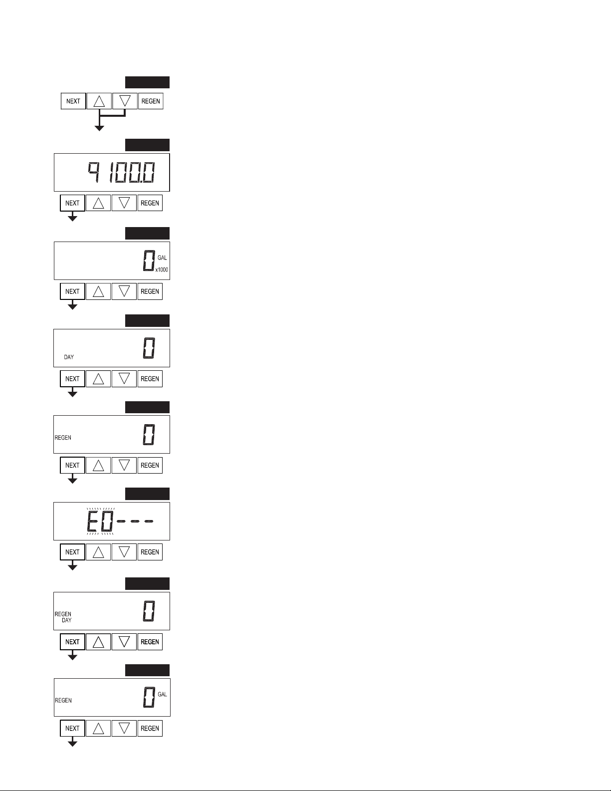
Step9D– Volume, reserve capacity used for last 7 days: If the valve is
setupasasoftener,ameterisinstalled,andSetVolumeCapacityisset
to“Auto,”thisdisplayshowsday0(fortoday)andflashesthereserve
capacity. Pressing will show day 1 (which would be yesterday) and
flashes the reserve capacity used. Pressing again will show day 2
(the day before yesterday) and the reserve capacity. Keep pressing
to show the capacity for days 3, 4, 5 and 6. can be pressed to move backwards in the day series. This
displaydoesnotappearif 1.0 issetinStep2CS,ifALTA orALT BareselectedinStep5CS,oranytime
the reserve capacity is not determined by the control.
Press NEXT at any time to go to Step 10D. Press REGEN to return to previous step.
Step 10D – Volume, 63-day usage history: This display shows day 0
(for today) and flashes the volume of water treated today. Pressing
willshowday1(whichwouldbeyesterday)andflashesthevolumeof
water treated on that day. Continue to press toshow the maximum
volumeofwatertreatedforthelast63days.Ifaregenerationoccurred
onthedaytheword“REGEN”willalsobedisplayed.Thisdisplaywill
show dashes if a water meter is not installed.
Press NEXT at any time to go to Step 11D. Press REGEN to return to previous step.
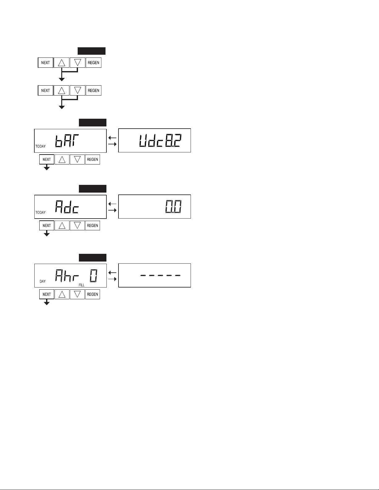
Step 11D – Twin Tank Valve transfer history: only displays when
1.0 was selected in Step 2CS. Use or to scroll through the last
10 tank transfers. The first position in the display ranges from 0 to 9
with the lowest number being the most recent transfer. The second
position in the display will be either “A” or “b”. If “A” then the tank
withthevalveonitwasinservice,if“b”the tankwiththein/outhead
onitwasinservice.Thenextthreedigitsrepresentthenumberofhoursagothatthetransferoccurred.The
displayalternateswiththevolumethatwastreatedbeforethetanktransferred.PressNEXTatanytimeto
go to Step 12D. Press REGEN to return to previous step.
Step 11D
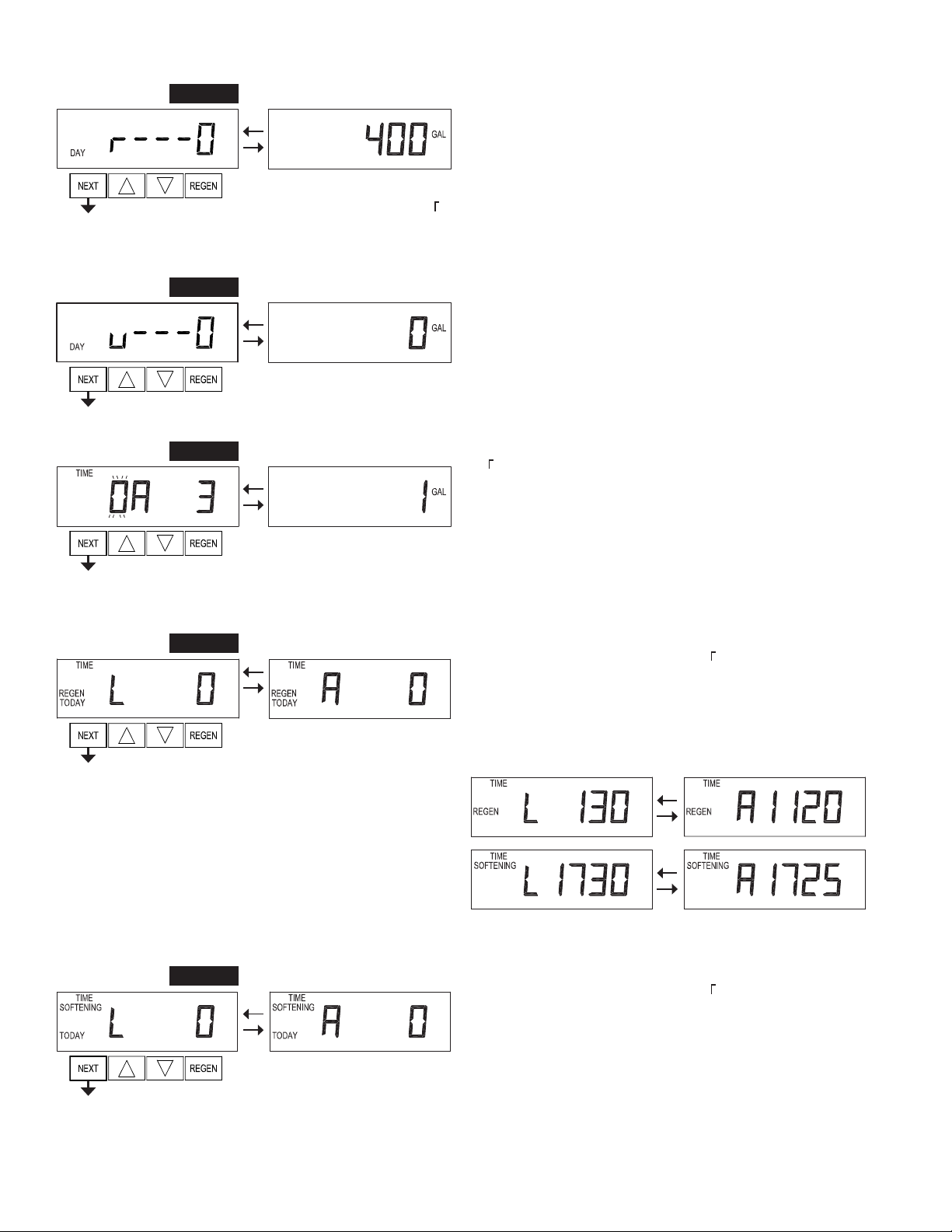
Step13D–MAVDriveHistoryinthedirectionofextendedpistonrod
position.Displaywillonlybeshownif1.0 isselectedinStep2CS,or
OFF is not selected in Step 4CS. Up to a four digit number
willappearafterthe“L”whichstandsforlatestand“A”whichstands
foraverage. Drivetimeis measuredin 1/100ofa second;i.e.,a 17.15
second move is displayed as “1715”. Press and hold and for 3
secondswhileinStep 13D to reset the MAV drive history in both the extended and retracted pistonrod
position. To view the old MAV drive history data see Step 12D.
Press NEXT at any time exit Diagnostics. Press REGEN to return to previous step.
Step 13D
EXIT DIAGNOSTICS
Step12D–MAVDriveHistoryinthedirectionofretractedpistonrod
position.Displaywillonlybeshownif1.0 isselectedinStep2CS,or
OFFisnotselectedinStep5CS.Uptoafourdigitnumberwillappear
afterthe“L”whichstandsforlatestand“A”whichstandsforaverage.
Drivetimeismeasuredin1/100ofasecond;i.e.,a17.10secondmove
is displayed as “1710”. Press NEXT at any time to go to Step 13D.
Press REGEN to return to previous step.
Step 12D
Press and hold and buttons for 3 seconds while in Step 12D to
resettheMAVdrivehistoryinboththeretractedandextendedpiston
rod position. To view the old MAV drive history data for retracted
and extended rod position press and hold REGEN and while in
Step 12D. Press NEXT to advance display to the old MAV drive
history.
Step 9D
Step 10D

SP Manual Page 17
Battery Diagnostics
Step 1BD - Press and simultaneously for 5 seconds and release. Press and simultaneously for
5 seconds and release. If screen in Step 2BD does not appear the lock on the valve is activated. To unlock
press , NEXT, , REGEN in sequence, then press and simultaneously for 5 seconds (twice) and
release.
Step 1BD
Step2BD – Battery Pack Status – Pack Voltage. Displays the daily
measured voltage of the battery pack under load. Press and hold
and to initiate an immediate test of the battery pack .
Press NEXT to go to Step 2BD. Press REGEN to exit Battery
Diagnostics.
Step 2BD
Step 3BD – Battery Pack Status – Charge Current. Displays the
currentmeasuredchargecurrent(inmA)ofthecontrolsolarpanelor
ACwalladapter.AflashingSETindicatesthatthecontroliscurrently
determiningwhethertoactivatethechargingcircuit.AflashingFILL
indicates that the charging circuit is currently activated. Pressing
will temporarily turn on the charging circuit. Pressing will
temporarilyturnoffthe charging circuit. Press NEXT to go to Step
4BD. Press REGEN to return to previous step.
Step 3BD
Step 4BD – Battery Pack Charge History. Displays the measure
mAhrchargeofthebatterypackoverthepast63days.REGENinthe
second display indicates that a regeneration occurred on that day.
PressNEXTtoexitBatteryDiagnostics. PressREGENtoreturnto
previous step.
Step 4BD
EXIT DIAGNOSTICS

Page 18 SP Manual
Revision History:
MAJOR UPDATE - NEW DISPLAYS AND OPERATION
4/3/2020
COVER
Added - Solar Powered
5/8/2020
PAGE 4:
Modified labels on #4 drawing
10/27/2020

SP Manual Page 19

Page 20 SP Manual
Form No. V3435SP – 10/27/2020 U.S. Patent: 6,776,901
Charger Water Treatment Products
8150 N. Lehigh Ave, Morton Grove, IL 60053
www.chargerwater.com/FAQ
Table of contents
Other Charger Control Unit manuals
Popular Control Unit manuals by other brands

Panasonic
Panasonic GP-US932CSAE operating instructions

JACLO
JACLO J-TH34 installation instructions

GARAN
GARAN EWS-102 System setup

Supermicro
Supermicro MicroBlade 6119M-T2N user manual

Mec
Mec Excelerator ME990S-2DFM Installation and operating manual

Bandini Industrie
Bandini Industrie GiBiDi BSC24 Instructions for installation