Reliable N2-Blast DDX-LP PrePaK Maintenance manual

Reliable Automatic Sprinkler Co., Inc., 103 Fairview Park Drive, Elmsford, New York 10523
Model DDX-LP N2-Blast® PrePaK™
Low Pressure Dry Pipe System
2” (50mm), 2-1/2” (65mm),
3” (80mm), 4”(100mm)
Bulletin 737 January 2021
Instructions for
Installation, Operation,
Care and Maintenance
Low Pressure Dry Pipe System
8 psi - 24 psi (0.6 bar - 1.7 bar)
System Air/Nitrogen Pressure
General Description
The Reliable Model DDX-LP PrePaK system with integrated
nitrogen generation (Sizes 2” (50mm), 2½” (65 mm), 3” (80
mm) and 4” (100 mm)) is a completely self-contained, super-
vised dry pipe system that can be readily installed within a floor
space of less than 7 ft2(0.65 m2). Refer to Fig. 1 for cabinet
dimensions. Installation of the DDX-LP PrePaK system requires
just three piping connections: the water supply, the sprinkler
system and the drain. Reference locations of these piping con-
nections are shown in Fig. 1. Independent electrical supplies
are required for the optional system air compressor (115 or 220
VAC) and the nitrogen generator (115 VAC).
Full assembly drawings for the units are available on the Reli-
able Automatic Sprinkler Company website (www.reliablesprin-
kler.com).
The Reliable Model DDX-LP N2-Blast®PrePaK system incor-
porates a South-Tek Systems FPS-900 pressure swing adsorp-
tion N2-Blast®nitrogen generator, complete with independent
air compressor, nitrogen storage tank, and control system. The
nitrogen generator is completely wired, tested, and integrated
with the Model DDX-LP PrePaK system, and supplies 98% pure
nitrogen to the piping network to limit electrochemical, galvanic,
and micro-biologically influenced corrosion (MIC). Operation
and maintenance information can be found in this bulletin as
well as the South-Tek Systems website (www.southteksystems.
com).
The heart of the Reliable Model DDX-LP PrePaK system is
the Model DDX-LP Dry Pipe Valve. The Reliable Model DDX-
LP Dry Pipe Valve is a hydraulically operated, mechanical valve
designed for use as a primary control valve in a low pressure
dry pipe valve system. The trim set used with the Model DDX-
LP Dry Pipe Valve contains the Reliable Model LP Dry Pilot Ac-
tuator releasing device. This Actuator allows the system air or
nitrogen pressure to be considerably less than the water supply
pressure (see Table A). The following benets are a direct result
of lower air pressure:
1. In refrigerated area systems, lower air pressure decreases
the possibility of ice plugs that could impede or prevent
the flow of water to re sprinkler heads in the event of re.
Note: N2-Blast®and Blast-off®are registered trademarks of South-Tek Systems, LLC.

2.
2. Lower air pressure allows for smaller capacity, lower cost
dehydration equipment, where required.
3. Lower air or nitrogen pressure can reduce water delivery
time when the system actuates, and in some cases, may
eliminate the need for an accelerator.
4. For systems supplied with nitrogen, low supervisory pres-
sure reduces the quantity of nitrogen required to maintain
the system pressure.
The Model DDX-LP PrePaK system is initially pressurized with
air provided by the factory-installed air compressor. Superviso-
ry pressure is provided and maintained by the integral nitrogen
generator and is monitored by a system pressure switch.
Note: Compressed air is not to be considered dry air and
may contribute to internal corrosion of piping, and/or ice plugs
in system piping. The factory-installed air compressor should
be utilized for initial ll only and make-up air only when the nitro-
gen generator is not active.
When a re sprinkler operates, there will be a loss of air or Ni-
trogen pressure in the sprinkler system piping which will cause
the Model LP-Dry Pilot Actuator to open. The opening of this
device allows the Model DDX-LP valve to flow water into the
system piping.
A Model B Hydraulic Manual Emergency Releasing station
is standard equipment in the Reliable DDX-LP PrePaK system.
It consists of an aluminum nameplate mechanically attached
to a ball valve. The valve handle in its OFF position is guarded
against accidental turning to the ON position (and system dis-
charge) by a nylon cable tie provided with the DDX-LP PrePaK
system assembly. The cable tie is designed to allow, in case of
an emergency, forceful turning of the valve handle to the ON
position.
Approvals
• The Model DDX-LP N2-Blast PrePaK dry-pipe system
is FM Approved as a factory-assembled Dry-pipe Sys-
tem to Approval Standard 1011/1012/1013, Deluge
and Preaction Sprinkler Systems.
• The Model DDX-LP dry-pipe valve and trim are FM Ap-
proved and cULus Listed.
• The South-Tek N2-Blast® Model FPS-900-RS nitrogen
generator is FM Approved to Approval Standard 1035,
Nitrogen Generators for Corrosion Mitigation.
Technical Data
1. The Reliable Model DDX-LP PrePaK system is rated for
a minimum water supply pressure of 20 psi (1.4 bar).
The 2”, 2-1/2”, 3”, and 8” sizes are rated for a maximum
pressure of 250 psi (17.2 bar), and the 4” and 6” sizes
are rated for a maximum pressure of 300 psi (20.7 bar).
Water temperature must be maintained between 40°F
and 140°F (4°C and 60°C).
2. Friction loss, expressed in equivalent length of Schedule
40 pipe and based on Hazen-Williams Formula is:
System Size Equivalent Length
2” (50 mm) 19.4 ft (1.3 m)
2½” (65 mm) 24.5 ft (1.8 m)
3” (80 mm) 28.9 ft (3.8 m)
4” (100 mm) 32.8 ft (17.7 m)
The equivalent length in the table above includes the Mod-
el DDX-LP valve, supply manifold tee, supply side control
valve, and the section of pipe above the Model DDX-LP
valve.
3. Shipping Weight:
System Size Weight
2” (50mm)
950 lbs (431 kg)2-1/2” (65mm)
3” (80mm)
4” (100 mm) 1075 lbs (488 kg)
4. Refer to Figure 1 for dimensions.
The following is a list of Technical Data Bulletins which de-
scribe the valves and devices which are used in the system:
Device Reliable Bulletin #
(unless otherwise noted)
Model DDX Deluge Valve Reliable Bulletin 519
Model DDX-LP Dry Pipe System Reliable Bulletin 338
Low Air Pressure Switch Potter, 5401564
Alarm Pressure switch Potter, 5400928
Installation Requirements
The automatic sprinklers utilized with the DDX-LP PrePaK
system must be UL and/or ULC Listed or FM Approved, as
applicable.
The steel enclosure and all the interconnecting piping must
be located indoors in a readily visible and accessible location
and in an area that can be maintained at a minimum tempera-
ture of 40°F (4°C). Note: Heat tracing is not permitted. The
Model DDX-LP PrePaK system operation is controlled by the
Model LP Dry Pilot Actuator. The introduction of moisture into
the system piping exposed to freezing temperatures can cre-
ate ice blockage, which could prevent proper system operation.
As a minimum, the air supply should be taken from the area
of lowest temperature within the protected area. The air sup-
ply system must be carefully designed to prevent plugging by
frost deposits. Special requirements, such as those in FME&R
“Installation Guidelines for Refrigerated Storage” may need to
be incorporated.
Optional Seismic Kit
Reliable part number 6501200041 (25” x 28” cabinet for 2”
-4” systems without nitrogen generator) and 6501200042 (30”
x 33” cabinet for 6” and 8” systems, and all units with nitrogen
generator) are seismic upgrade kits required to make the Re-
liable PrePaK OSHPD compliant. One kit is required for each
PrePaK (reference Caution Sheet 331).

3.
Fig. 1

4.
Hydrostatic Testing of DDX-LP Valves and DDX-
LP Systems
As required by NFPA 13, re sprinkler systems with working
pressures up to and including 150 psi are to be hydrostatically
tested at a water pressure of 200 psi. Fire sprinkler systems with
working pressures above 150 psi are required to be hydrostati-
cally tested at 50 psi above the system working pressure. In ad-
dition to the hydrostatic tests described above, dry pipe systems
require an additional low pressure air test.
In some cases, hydrostatic testing (in accordance with the
NFPA 13 requirements noted above) will result in pressures that
exceed the working pressure of the valve and trim kit for the two-
hour test period.
The valve and applicable trim kit have been tested, approved
and listed under these conditions and as such, hydrostatic test-
ing in accordance with NFPA 13 is acceptable. In addition, the
clapper can remain in the closed position and the trim kit need
not be isolated, as each has been designed to withstand hydro-
static testing as required by NFPA 13.
Subjecting the valve and trim to pressures higher than their
rating is limited to the hydrostatic test as referenced by NFPA13.
It does not address the occurrence of a “water hammer” effect,
which may damage the valve. A “water hammer” in the water
supply piping of the valve can create pressures in excess of the
rated pressure and should be avoided by all necessary means.
This condition may be created from improper re pump set-
tings, underground construction work, or an improper venting
of trapped air in the water supply piping.
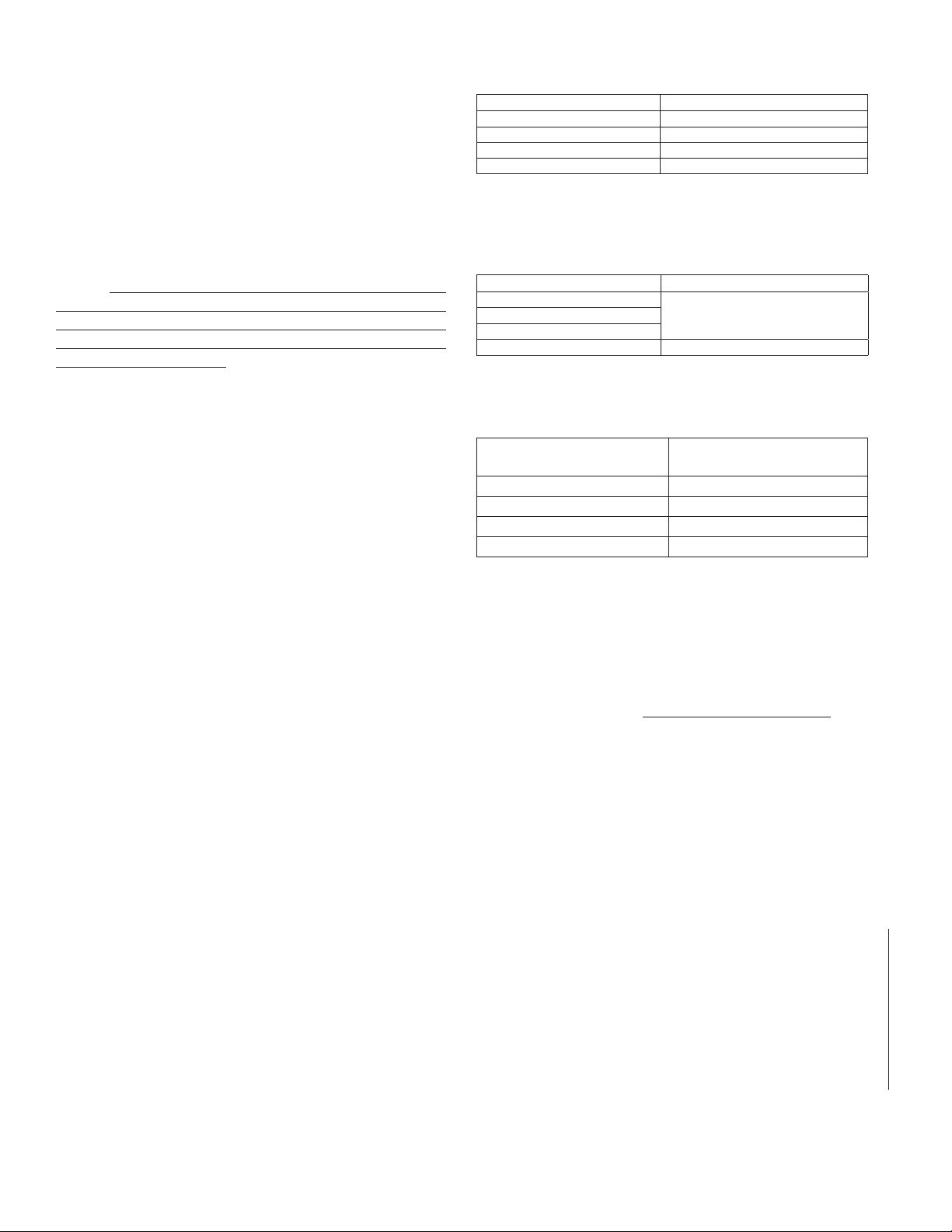
System Supervisory Pressure Requirements
The DDX-LP PrePaK system includes gauges indicating the
air/nitrogen and water pressures on the Model DDX-LP sys-
tem. Table A species the air or nitrogen pressure to be main-
tained in the sprinkler system piping based on the water supply
pressure. The factory installed Pressure Maintenance Device
in the unit automatically regulates makeup air or nitrogen flow
to maintain pressure with normal leakage from system piping,
while restricting the flow of makeup air or nitrogen to the sys-
tem. Please note that when the optional Model B1 Accelerator
is to be utilized to expedite water-delivery time, the air or nitro-
gen pressure must be not less than 15 psi (1.0 bar).
The factory-installed system low air pressure switch may need
on-site adjustment to correspond with the air pressure values
found in Table A. Adjustment, if required, should be made ac-
cording to Potter Bulletin 5401564 included with the switch.
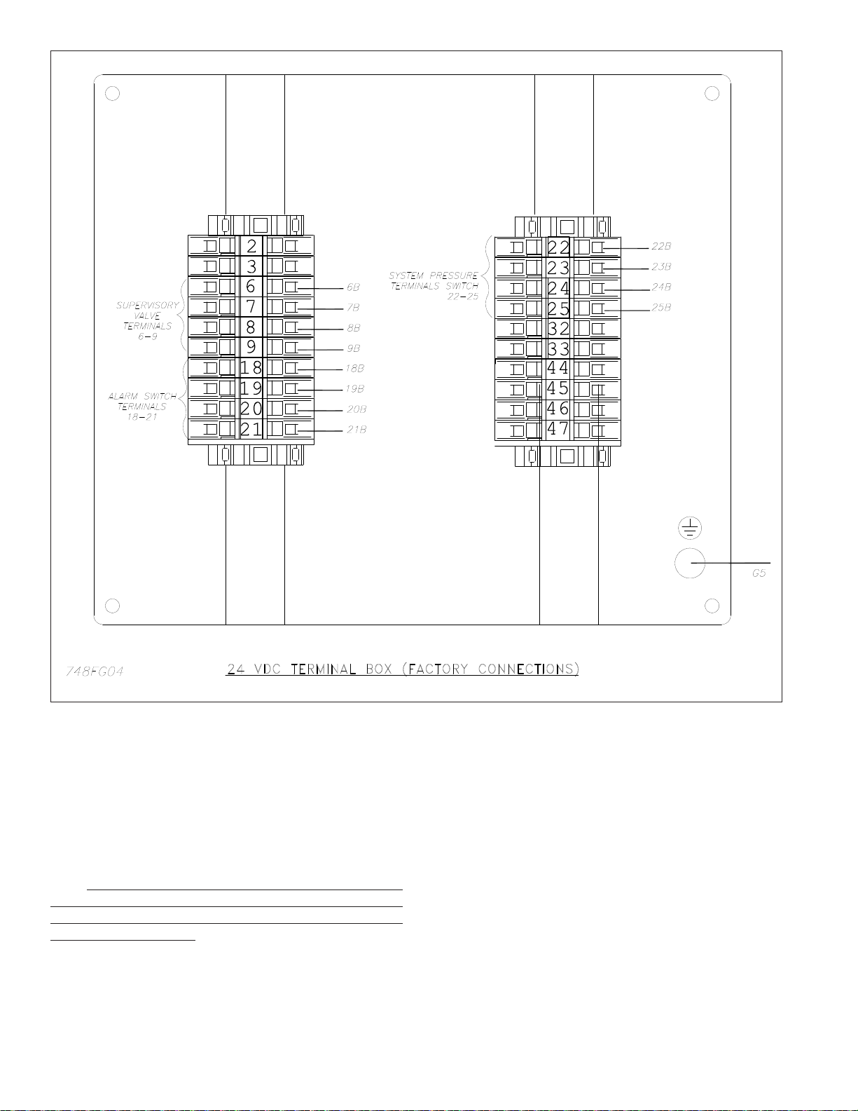
System Electrical Requirements
All 24 VDC electrical connections in the Reliable Model DDX-
LP PrePaK system are translated to a water tight terminal box
mounted on the inside of the enclosure. All eld wiring connec-
tions are made at this terminal box.
A separate power connection is provided for the optional air
compressor.
Note: The air compressor must be connected to a grounded
metallic, permanent wiring system, or an equipment grounding
terminal or lead on the product. Power supply wiring must con-
form to all required safety codes and be installed by a qualied
person. Check that the supply voltage agrees with that listed on
compressor nameplate.
Maintenance
The Reliable DDX-LP PrePaK system and associated equip-
ment shall periodically be given a thorough inspection and test.
NFPA 25, Standard for Inspection, Testing and Maintenance of
Water Based Fire Protection Systems, provides minimum main-
tenance requirements. Systems should be tested, operated,
cleaned and inspected at least annually, and parts replaced as
required. Periodically open the condensate drain valve beneath
the air tank to drain any condensate accumulation. Reliable
Technical Bulletins 338 and 519 provide additional information
for maintaining the Model DDX-LP Deluge Valve.
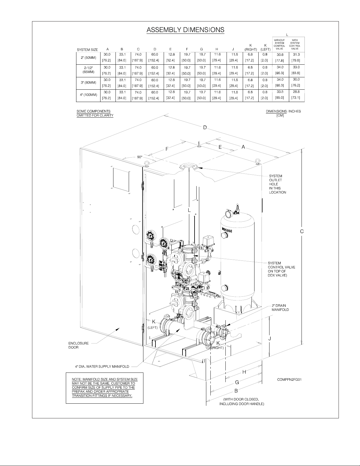
System Setup (Refer to Figure 2)
1. Close the main valve controlling water supply to the Model
DDX-LP deluge valve. Also, close the two ¼” valves sup-
plying air or nitrogen to the system.
2. Close the pushrod chamber supply valve.
3. Open the main drain valve and drain the system.
4. Open all drain valves and vents at low points throughout
the system, closing them when flow of water has stopped.
5. Open the Manual Emergency Release valve. Note: The
above steps accomplish the relieving of pressure in the
pushrod chamber of the deluge valve.
6. Push in the plunger of ball drip valve to force the ball from
its seat, and drain any water in the alarm line.
7. Push in and rotate the deluge valve’s external reset knob
counter-clockwise (when facing valve) until you hear a dis-
tinct clicking noise, indicating that the clapper has reset.
Note: The reset knob can be rotated only after pressure
in the pushrod chamber is reduced to atmospheric condi-
tions (0 psig).
Water Pressure psi (bar) System Air or Nitrogen Pressure
psi (bar)
Maximum Not Less Than
20 (1.4) 8 (0.6)
30 (2.1) 10 (0.7)
50 (3.4) 12 (.8)
75 (5.2) 13 (.9)
100 (6.9) 15 (1.)
125 (8.6) 16 (1.1)
150 (10.3) 17 (1.2)
175 (12.1) 18 (1.2)
200 (13.8) 19 (1.3)
225 (15.5) 21 (1.4)
250 (17.2) 22 (1.5)
275 (19.0) 23 (1.6)
300 (20.7) 24 (1.7)
Table A
Notes:
1. Supervisory air or nitrogen pressure should not exceed 30 psi (2.1 bar).
Excess pressure may result in damage to the actuator.
2. Fastest valve operation is achieved with supervisory air or nitrogen
pressure indicated; however, pressure must never be less than the
minimum specied in the table above.
3. Air maintenance devices that maintain a constant pressure are
recommended; however, if a tank-less compressor is used, the
“compressor on” setting of the pressure switch must never be lower than
the minimum pressure in the table above.

5.
8. Inspect and replace any portion of the sprinkler system
subjected to re conditions.
9. Verify that the following valves are in their respective posi-
tions prior to continuing:
Manual Emergency Release - open
Main Drain Valve - open
Alarm Line Valve - open
Alarm Test Valve - closed
Condensate Drain valve - closed
Air/Nitrogen Supply Valves - closed
10. Open pushrod chamber supply valve and allow water to
ll the pushrod chamber. Close the Manual Emergency
Release valve after any trapped air has had a chance to
escape from the deluge valve’s pushrod chamber.
11. Upon seeing this solid flow of water coming out of the
Model LP Dry Pilot Actuator, open the Rapid-Air Fill Valve
thereby rapidly applying compressed air or nitrogen into
the Model LP Dry Pilot Actuator and the sprinkler system
until the pressure conforms to Table A levels, as indicat-
ed by the system air pressure gauge. The Model LP Dry
Pilot Actuator will eventually close during this pressuriz-
ing process and water will stop flowing through the drain
tube. At this point, the pressure gauge on the pushrod
chamber pressure will equalize to the available water
supply pressure. Once the actuator is set up correctly,
close the Rapid-Air Fill Valve and open the Regulated Air
Shutoff Valve.
Note: For systems using nitrogen as the primary source,
the system may be set up using the nitrogen source fol-
lowing the steps above. The air compressor, if present,
may then be placed into operation as the backup pneu-
matic source.
12. Open the alarm line valve.
13. If the Model B1 Accelerator Kit is installed, open valve P.
Prior to opening valve P, be sure that the Model B1 Ac-
celerator has been successfully reset per Reliable Tech-
nical Bulletin 323.
Note: The B1 Accelerator requires a minimum of 15 psi
(1,0 bar) supervisory air or nitrogen pressure for proper
operation.
14. Slightly open the main valve controlling water supply to
the Model DDX-LP Deluge Valve. This will begin to ll the
deluge valve beneath the clapper with water. Once any
trapped air has been vented, close the main drain valve.
Observe if water leaks through the ball drip valve into the
1” drain manifold through the clear tubing. If no leakage
occurs, the deluge valve clapper is sealed. Fully open
the main valve controlling the water supply to the Model
DDX-LP Deluge Valve and that it is properly monitored
15. Verify that the pushrod chamber supply valve is open.
16. Secure the handle of the Model B Manual Emergency
Station in the OFF position with a nylon tie (supplied with
the assembly).
Inspection And Testing Of The DDX-LP PrePaK
Systems (Refer to Figure 2)
1. Water supply — Verify that the valve controlling water
supply to the deluge valve is opened fully and properly
monitored.
2. Pushrod Chamber supply — Verify that the valve sup-
plying water to the pushrod chamber is open.
3. Other trimming valves — Verify that the alarm line valve
is open as well as all of the pressure gauge valves. The
main drain valve, alarm test valve, and condensate drain
valve should be closed.
4. Ball drip valve — Push in on the plunger to be sure the
ball check is off its seat. If no water appears, the deluge
valve’s water seat is tight. Inspect the small bleed hole lo-
cated on the underside of the Model DDX-LP Deluge Valve
pushrod chamber for leakage.
5. System air pressure — Verify that system air pressure
is in conformance with the values posted in Table A for the
supply water pressure.
6. Releasing device — Check the outlet of the (Model LP
Dry Pilot Actuator and Model B Manual Emergency Sta-
tion) for leakage. Also verify that tubing drain lines from
releasing devices are not pinched or crushed which could
prevent proper releasing of the deluge valve.
7. Testing alarms — Open the alarm test valve permitting
water from the supply to flow to the alarm pressure switch
and to the mechanical sprinkler alarm (if present). After
testing, close this valve completely. Push in on the plunger
of ball drip until all of the water has drained from the alarm
line.
8. Operational test — Open the Model B Manual Emergen-
cy Station or, alternatively, reduce air/nitrogen pressure on
the system. Note: An operational test will cause the Del-
uge Valve to open and flow water into the sprinkler system.
9. Secure the Model B Manual Emergency Station in the
OFF position with a nylon tie (included with the assembly)
after the deluge valve is reset.
Testing the Model DDX-LP Deluge Valve With-
out Flowing Water (Refer to Figure 2)
1. Close the valve controlling water supply to deluge valve
and open the main drain.
2. Verify that the pushrod chamber supply valve is open, al-
lowing water to enter the pushrod chamber.
3. Close the air/nitrogen supply to the sprinkler system.
4. Decrease pneumatic pressure in the system by opening
the condensate drain valve, until the Model LP Dry Pilot
Actuator operates. Doing so will result in a sudden drop of
water pressure in the deluge valve pushrod chamber.
5. Reset the system per the directions listed in “System Set-
up” section of this bulletin.
(cont. bottom of page 8)

6.
Fig. 2
Model DDX-LP Low Pressure Dry Pipe System
Valve Legend
(Note: Some items omitted for clarity)

7.
Fig. 3

8.
Fig. 4
Draining Excess/Condensate Water From System
1. Close the main valve controlling water supply to the Model
DDX-LP system.
2. Close the pushrod chamber supply valve, and open the main
drain valve.
3. Slightly open the condensate drain valve until all water has
drained, then close.
Note: Leaving the condensate drain open for an extended pe-
riod of time may allow excess air/nitrogen to bleed off and result
in accidental release of the Model LP Dry Pilot Actuator and/or
the Model DDX-LP valve.
4. Close the main drain valve. Allow the system air/nitrogen
pressure to return to its previous level. Open the pushrod cham-
ber supply valve rst, and then open the main valve controlling
water supply to the system.

FPS-900-RS Nitrogen Generator
General
This manual provides instruction for the proper use and
maintenance of South-Tek Systems N2-Blast®FPS-900-RS.
South-Tek Systems and Reliable are not responsible for dam-
ages when using this in manners not approved by South-Tek
Systems and Reliable. The user(s) of this document should
confer any questions with a qualied South-Tek Systems
representative on its commissioning and correct use. Please
contact South-Tek Systems with any question or concerns at:
South-Tek Systems, LLC
2940 Orville Wright Way Ste 600
Wilmington, NC, 28405
Tel: (888) 526-6284
Email: Inf[email protected]
http://www.southteksystems.com/
Important Information
All personnel (and their supervisors) installing, operating, and
maintaining the N2-Blast®must read and fully understand
this manual prior to installing, operating or performing main-
tenance. The N2-Blast®produces nitrogen (N2) at a low flow
rate, which quickly dissipates into the air. N2gas is not poison-
ous, but do not directly inhale since high concentrations can
cause asphyxiation. Install the unit in a well-ventilated room
that is not sealed off from normal living space air changes.
All personnel involved with the installation, operations, and
maintenance of the N2-Blast®must follow safe working prac-
tices, including OHSA and local health/safety code regula-
tions.
Safety Guidelines
The following section outlines the basic safety consider-
ations about installation and operation of the N2-Blast®FPS-
900-RS. For other equipment used with the nitrogen genera-
tor, such as external air compressors, and dryers, refer to the
manufacturer’s safety guidelines.
Using the N2-Blast®FPS-900-RS correctly is important
for safety and trouble-free operation. Wrong use can cause
damages to the system or can lead to incorrect gas supply.
The nitrogen generator produces nitrogen at a low flow rate,
which quickly dissipates into the air. Nitrogen is not poison-
ous, but do not directly inhaled, since high concentrations,
can cause asphyxiation. Install the unit in a well-ventilated
room, unsealed off from normal living space air changes.
Warning: Install the unit in a within a well-ventilated room,
one that is not sealed off from normal living space air chang-
es.
Read carefully and act accordingly before operating or re-
pairing the unit:
• The operator must use safe working practices and
rules when running the nitrogen generator.
• The owner is responsible for always keeping the unit
in safe working conditions.
• Always use approved parts when performing mainte-
nance and repairs. Make sure that replacement parts
meet or exceed the original parts’ specication.
• Only competent individuals, trained and authorized,
can install, operate, perform maintenance and repair.
• Isolate incoming and outgoing pressures to the gen-
erator, and depressurize the service or repair section
before performing any mechanical work, including
changing the lters.
• Vent the nitrogen generator’s exhaust gas outside or
to a large, well-ventilated room to avoid suffocation
due to lack of oxygen.
• Wear safety glasses if the cabinet door is open while
the machine is running.
• Use ear protection when the equipment is running.
NOTE: Always following local and site safety regulations
in conjunction with this manual. Correct use of the nitro-
gen generator is important for personal safety. Incorrect
safety practices can cause damage to the individual and
equipment.
Follow safe working practices, OSHA, and local health and
safety regulation when maintaining the N2-Blast® FPS-900-RS.
Air Supply
The N2-Blast®FPS-900-RS includes a built-in air compres-
sor to supply gas to the nitrogen generator. It is not for perform-
ing quick lls; a separate suitable air compressor should be
used to ll the system.
9.

Electrical Requirements
The N2-Blast®FPS-900-RS requires 120VAC / 50-60hz /
1ph and draws < 8A. A 240VAC option is also available. It has
a built-in 20A over-current protection device and comes with
a standard 3-prong US power cord for the electrical connec-
tion (unless otherwise specied). It comes with UL 508A ICP
certication, and the electrical schematics are available upon
request.
Site Specications
Unless designed otherwise, install in a nonhazardous in-
door location with temperatures between 40-100°F (4°- 38°C).
For ease of maintenance, troubleshooting, and minimizing
pressure drop, install the equipment in the same area. Leave
enough space around the generator and other equipment for
routine maintenance.
Key Features
Air Compressor
An oil-less internal air compressor has an engineered
dampening system reducing vibration and noise throughout
the cabinet. The air compressor has a pre-lter to catch small
particulates that can cause damage. The recommended re-
placement for the pre-lter is 1000 run hours or 1-year, which-
ever comes rst. Dirtier environments may need more frequent
changes. Consult with the supplier for a different lter mainte-
nance schedule if installing in a dirty environment.
Air Filters
The generator has an air inlet pre-lters and two lters be-
tween the compressed air and O2separation beds - the par-
ticulate and coalescing. The 5-micron particulate lter catches
the bulk particles, and the 0.1 micron coalescing catches the
remaining smaller particles. Both lters feature an auto-drain
that drains any water buildup within the lter housing. These
drain lines are on the cabinet’s bottom right side. Connect
these drain lines to a safe location.
Programmable Logic Controller
An integrated PLC within the cabinet that features smart
timing to maximize the generator’s performance. It controls
the valve timing and sequencing to move compressed gas
throughout the system. It also has a smart feature to automati-
cally switch between different “modes” based on the current
run stages (see Chapter 7: System Operation for more about
the unit’s functionality).
Safety Relief Valves
The installed ASME safety relief valves add additional safe-
ty to protect component failures.
Nitrogen Tank
A nitrogen tank inside the cabinet comes with ball valves,
safety relief, and a gauge.
Automatic Cut-In and Cut-Out
The generator starts and stops based on a pressure switch.
Do not adjust the factory preset cut-in and out pressure without
rst consulting with South-Tek Systems.
Patented BlastOff®– Leak Detection System
The “BlastOff®Leak Detection” is a patented feature which
sends an alarm if it detects a possible gas leak. The alarm sig-
nal can be an audible, visual, and dry contact connection to the
“Building Management System (BMS)”. Power cycle the unit to
reset the alarm but avoid doing this without nding the cause,
as it will shorten the generator’s life.
N2-Blast® FPS-900-RS Specications
• Nitrogen Purity 98.5+%
• Integrated Installation in Reliable PrePaK system
• Display Hours/Power on/Operating
• N2Storage Pressure 60-70 PSIG (±5%)
• Cabinet Port Connections 1/2” NPT Female
• Electrical 110-220V / 50-60Hz / 1Phase; 20 Amp
Breaker
• Compressor Integral / Oil-Free
• Ambient Temperature 40° to 100°F
• Noise Level (dbA) < 90 dbA
Operation
The nitrogen generator uses valve sequencing to produce
nitrogen. The design meets specications of a re protection
system. Consult with South-Tek System for written approval
before performing any eld changes or customization. Unau-
thorized changes void all warranties and may cause damages
or malfunctions to the system.
This section describes the major control functions and in-
strumentations associated with the nitrogen generators. All
programs are proprietary and password protected from the
factory. Do not alter any controls or instrumentations. Changes
without South-Tek Systems’ written consent voids the perfor-
mance specications.
Controller Modes
To utilize the buttons on the front of the controller the unit
must be in “S” or “Switch” mode and unlocked. If the system
is displaying “LOCK”, the Mode Select Button may be pressed
and held to unlock the controller (repeat this step if a system
lockout is desired). To change to Switch Mode, press the Mode
Select Button when the controller is unlocked until the System
Mode Indicator displays “S”. This mode allows access to two
features:
• Alarm Simulation (5) – Hold the Alarm Simulation Button
for 3 seconds or press the lter replacement reset button
3 times within 3 seconds to activate. This will simulate an
alarm condition and trip the alarm dry contact in the unit
for 2 seconds so that proper functioning can be conrmed.
• Filter Change Reset (0) – When a new FRP (Filter Re-
placement Kit) is installed, the 1000- hour lter change
time must be reset. After replacing the lter elements,
press and hold the Filter Change Reset Button for 7 sec-
onds. An audible beep will conrm that the time is reset
and lter alarm will be reset. (Note: this will also trigger the
Customer Alarm Relay for one second)
10.

Normal Run/Standby Mode (run/StdbY)
“Run” mode is when the FPS-900-RS is producing ni-
trogen and supplying it to the storage tank. The system will
automatically enter “Standby” mode when the tank is fully
pressurized (70 PSIG ±5 PSIG). It will remain in “Standby”
mode until the tank pressure falls 7-10 psig.
To run the system in normal run mode:
1. Connect power to the system.
2. Open the nitrogen generator’s 3-way outlet ball
valve to nitrogen-out position.
3. On the nitrogen tank, open the gas inlet valve.
4. Push the On/Off toggle button on the upper right
control panel to the “On” position (up) and the sys-
tem will automatically turn on and start lling the
storage tank with nitrogen.
To stop the system:
1. Switch the nitrogen generator’s 3-way outlet ball
valve to the bypass position.
2. System will automatically stop once it reaches the
cut-out pressure of approximately 65-75 PSIG.
3. In the case of an emergency shut off, push the On/
Off toggle button on the upper left control panel to the
“Off” position. The unit will shut down immediately.
Alarm Mode
When an alarm mode is activated, it will trigger the au-
dible buzzer, alarm contact, and flash the cause of the alarm
on the screen. The customer alarm contact wiring can be
viewed on the supplied wiring diagram. The customer alarm
dry contact is constantly energized and will constantly illu-
minate the LED indicator on top of the contact. This is so
when there is no power or power is lost on the system, the
contact will de-energize and show a fault condition. The
alarm contact has a max rating of 6A at 250VAC and 2A at
24VDC.
Bypass Mode (BPASS)
During the 30-minute re protection piping system ll test
or an issue with the generator is detected, the operator can
switch the system into manual bypass mode by turning the
handle on the 3-way ball valve to the bypass position. With
the handle in the “Bypass Mode”, the bypass alarm triggers
the audible buzzer, alarm contact, and flashes “BPASS” on
the controller’s 7-segment display. The alarm will turn off
once the handle is back to normal run position.
BLASTOFF® Alarm Mode (B-Off)
The nitrogen generator activates a BlastOff® Alarm when it
detects potential leaks or nitrogen being overdrawn. The Blast-
Off® Alarm will trigger the audible buzzer, alarm contact, and
flash “B-OFF” on the controller’s 7-segment display. Inspect
and test the system for leaks and component failures. Power
cycle the unit to reset the alarm but avoid doing this without
nding the cause, as it will shorten the generator’s life. Contact
South-Tek System or the local installer for further troubleshoot-
ing.
Low System Pressure Alarm Mode (Lo-n2)
The low system pressure alarm activates when a sys-
tem pressure is detected below the normal functioning limits
of the nitrogen generator. This may be from an issue with
the generator, a supply valve being shut off, or caused by a
large leak in the re protection system.
Power Loss Alarm Mode (-----)
The Power Loss alarm activates when the nitrogen gen-
erator loses power for any reason. This will cause the alarm
contact to trigger.
Filter Replacement Alarm Mode (FILTr)
Once the generator has been running for 1000 hours or
more, the lter replacement alarm will activate. Replace the
lters according to Section 9 Maintenance. After replacing
the lter elements, press and hold the Filter Change Reset
Button for 7 seconds. An audible beep will conrm that the
time is reset, and lter alarm will shut off if it is active. (Note:
resetting this will also trigger the Customer Alarm Relay for
one second)
Start-up Procedures
Use caution when working with pressurized gas. Always
leak check every line before using the system. Note: Line
leaks will cause the N2-Blast®FPS-900-RS to run exces-
sively, shortening its life and possibly causing excessive
wear on the compressor.
1. Visually inspect the unit to ensure no damage occurred
during shipping and handling.
2. Check the power connection is correct.
3. Turn the 3-way ball valve on the system output to the
“Bypass” position.
4. Open the inlet ball valve on the nitrogen storage tank if
it is closed.
5. Push the power button on the top left of the cabinet to
the “On” position (up). The air compressor will power
on if the storage tank is under pressurized. If neither the
compressor nor PLC display power on, check the wiring
and supply power to the generator.
6. Once the system is running, the pressure gauge will in-
crease to 65-70 PSIG within 30 minutes or less. While it
is running, check the system for leaks to ensure proper
functionality.
a. Once it reaches 65-70 PSIG, the system will enter
“Standby” mode and automatically shut off the inter-
nal air compressor. Check the controller on the control
panel for the “StdbY” display.
b. Once in standby, note the pressure reading on the
tank pressure gauge. Monitor the pressure for the next
5 minutes for any loss in pressure. If there is a pressure
drop, check for leaks around connection ttings, other-
wise proceed to the next step.
7. Switch the 3-way ball valve on the system output to the
“Nitrogen Out” position and the system will turn on and
ll the storage tank with nitrogen.
8. Completely ll the storage tank and allow the nitrogen
generator to go into standby mode.
9. Once in standby mode, monitor the tank pressure gauge
for 5 minutes and ensure no signicant leaks are in the
sprinkler system.
11.

Air Intake Filter
The integrated air compressor, of the N2-Blast® FPS-900-
RS, has an air intake pre-lter. It prevents particles from entering
the compressor housing and damaging internal components.
Replace this lter once per year or every 1000 hours, whichever
comes rst. To do so, remove the pre-compressor lter cap by
twisting it clockwise. Remove the old element and use a clean
dry cloth to clean the lter bowl before installing the new ele-
ment.
Air Filter Replacement
The particulate and coalescing lters, after the air compres-
sor, are designed to capture particulate
and moisture prior to entering the rest of the system. These l-
ters need to be replaced once per year or every 1000 hours,
whichever comes rst.
Note: Annual Filter replacement kit part # FRP-007
Follow these instructions to replace lters:
1. Turn off the unit and remove the front cabinet door.
2. Locate the air lters on the bracket in the top-left of the
cabinet (see Figure 10).
3. Make sure the lters are completely depressurized by
checking the pressure gauge.
4. Remove both lter bowls by turning them counter-
clockwise.
5. After removing the lter bowls, rinse debris out of the
bowls with warm water.
6. Dry the bowls with a clean dry cloth and replace old
O-rings with the ones in the kits and lubricate the seals.
7. Change the lter elements:
a. Particulate Element - Pull the plastic element hous-
ing out of the lter bowl. Twist off the black plastic cover
and pull off the particulate element. Install the new ele-
ment in the reverse order.
b. Coalescing Element - Twist the coalescing element
counter-clockwise. Install the new element in the re-
verse order.
8. After replacing all elements and O-rings and cleaning
the bowls, install the bowls back to their corresponding
lter housings. Hand-tighten only.
After replacing the lters, check the lter bowls for leaks by turn-
ing on the unit momentarily. Turn the unit off to reinstall the front
cover and then power the unit back on. Once powered up, the
air compressor will turn on and the system will start producing
nitrogen.
Key Contacts
Contact your local provider/installer for any questions about
the performance and/or maintenance of the system. They will be
best suited to answer your questions and your quickest solution
on any issues you may have. If they cannot be reached, contact
the manufacturer at:
South-Tek Systems, LLC.
tel (888) 526-6284 fax (910) 332-4178
Email: inf[email protected]
FAQS
1. Power Issues
If the N2-Blast®FPS-900-RS does not have power, the produc-
tion and storage of nitrogen will become apparent once the stor-
age pressure drops.
• Check the power cord.
• Has the building’s circuit breaker or GFCI tripped? Locate
the breaker and reset. If breaker continues to trip, you may
have that circuit overloaded.
2. Pressure Issues
The N2-Blast®FPS-900-RS will produce and store Nitrogen (N2)
at 70 (+/-3) psig. Once the storage tank reaches 70 (+/-3) psig,
the system will go into Standby Mode. When the pressure drops
by about 7-10 psig, the system will go into Run Mode and begin
to rell the storage tank. Contact the manufacturer or factory
trained technician if system does not properly operate within
these ranges
Nitrogen Pressure Check:
The pressure gauge on the storage tank should be between
60 and 70 psig. If the pressure is low, check the following:
• Check the power.
• Find out if re protection system is being tested.
• Check for leaks throughout system.
3. Leaks
As with any gas system, only use a spray bottle on non-electri-
cal equipment to nd leaks. Fix or replace leaking ttings or old
hose. Push-to-connect ttings will show bubbles and typically
have up to a 5ccm acceptable leakage rate. Contact your local
provider/installer for help.
12.

Fig. 5 - Nitrogen Generator Filter Locations
13.

Notes:
(1) Manifold size in PrePaK system may differ from system size (see Figure 1). Customer to conrm size of supply pipe
to PrePaK system and order appropriate transition ttings if necessary.
(2) System capacity based on 20 psi supervisory pressure. Air compressor sizing may differ if sprinkler system has an
uncommon volume. If “0 = None” option is chosen, customer to provide separate compressor or other pneumatic
source.
Optional Seismic Kit: Reliable part number 6501200041 (25” x 28” cabinet for 2” -4” systems without nitrogen
generator) and 6501200042 (30” x 33” cabinet for 6” and 8” systems, and all units with nitrogen generator) are
seismic upgrade kits required to make the Reliable PrePaK OSHPD compliant. One kit is required for each PrePaK
(reference Caution Sheet 331).
DDX-LP Valve Size/System
Side Control Valve
X
Air Compressor
Y
System Air Devices
Z
2 = 2” 0 = None 8 = Nitrogen Generator
0 = 2-1/2” 1 = 1/2 HP 115 VAC
(Systems up to 580 gallons)
9 = Nitrogen Generator &
Model B1 Accelerator
3 = 3” 2 - 1 HP 115 VAC
(Systems up to 1170 gallons)
4 = 4” 3 = 1/2 HP 220 VAC 60 Hz
(Systems up to 580 gallons)
A = 2” w/ System Side Control
Valve
4 = 1 HP 220 VAC 60 Hz
(Systems up to 1170 gallons)
B = 2-1/2” w/ System Side Control
Valve
C = 3” w/ System Side Control
Valve
D = 4” w/ System Side Control
Valve
655 X(1) 3 0 0 Y(2) Z 0
Ordering Information: Model DDX Type DDX-LP PrePaK system with N2-Blast®Nitrogen Generator
Reliable Automatic Sprinkler Co., Inc.
(800) 431-1588 Sales Ofces
(800) 848-6051 Sales Fax
(914) 829-2042 Corporate Ofces
www.reliablesprinkler.com Internet Address
Manufactured by
Recycled
Paper
Revision lines indicate updated or new data.
EG. Printed in U.S.A. 01/21 P/N 9999970550
The equipment presented in this bulletin is to be installed in accordance with the latest published Standards of the National Fire Protection Association, FM Global, or
other similar organizations and also with the provisions of governmental codes or ordinances whenever applicable.
Products manufactured and distributed by Reliable have been protecting life and property for almost 100 years.
Other manuals for N2-Blast DDX-LP PrePaK
1
Table of contents
Other Reliable Control Unit manuals
Popular Control Unit manuals by other brands

Honeywell
Honeywell Excel 5000 System Series installation instructions

handtmann
handtmann 12504 operating manual

Metso
Metso Jamesbury 4000 B Installation maintenance and operating instructions

Brocade Communications Systems
Brocade Communications Systems MLXe Series Hardware installation guide

Solar Stik
Solar Stik PDM 3000 Operator and maintenance manual

Wessel Hydraulik
Wessel Hydraulik PRV-1DI quick start guide