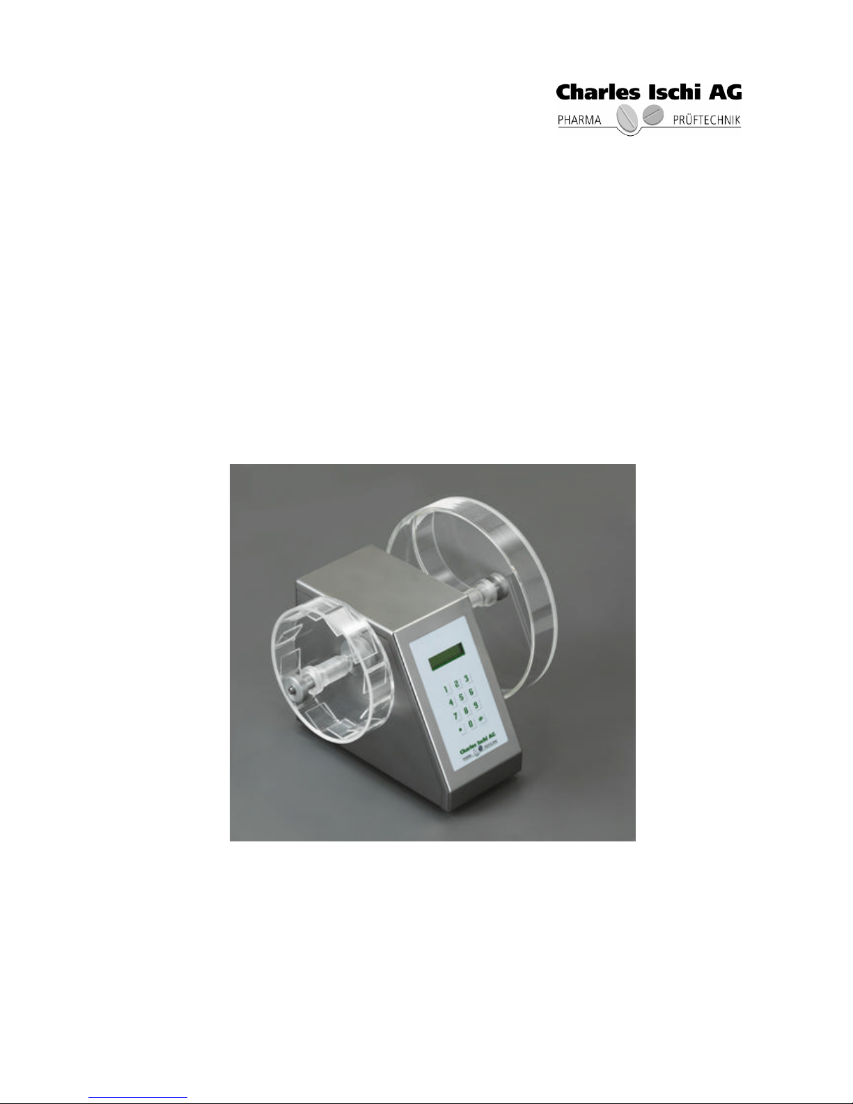
Charles Ischi AG AE-1 User manual
OME_306511 1
OPERATING INSTRUCTIONS
ABRASION AND
FRIABILITY TESTER
AE-1
Version 2.06
14.11.2006
Rights reserved for technical changes

OME_306511 2
TABLE OF CONTENTS
Page
1. START UP.................................................................................................................................3
2. USER GUIDANCE...................................................................................................................4
3. TECHNICAL DATA.................................................................................................................6
4. FINAL ASSEMBLY CONTROL TEST .................................................................................7
5. SERVICING...............................................................................................................................8
6. TROUBLESHOOTING............................................................................................................9
7. SPARE PART LIST...............................................................................................................10
8. CE –CONFORMITY DECLARATION................................................................................11
9. DECLARATION OF CONFORMITY WITH PH-EUR5.0/2005 AND USP29 NF2006.12
10. DRAWINGS.............................................................................................................................13
11. TECHNICAL INFORMATION –Install support 10° angle ............................................15

OME_306511 3
1. START UP
1. Operating voltage
Before plugging the machine in, check the voltage selector on the rear panel.
2. Mounting the test drums
The tester is delivered with power cable and operating manual. The test drums are
avaliable as an option in 2 versions: Friability test or abrasion test. The test drums are
prevented from rolling by tabs on the inside and a quick release nut on the outside of the
shaft.
3. Connectingpower
After the correct operating voltage ( point 1) has been selected the power cable can
be connected to the machine.

OME_306511 4
2. USER GUIDANCE
2.1.Switch machine on
After the machine is switched on the machine version is shown in the display first,
then the actual operating parameters:
Line 1: Preset rotation speed / PARAM *
Line 2: Time or total counts / START #
The machine can be operated using preset time or total counts, as desired.
2.2.Setting time or rotations:
Press * (PARAM) button
With the button # (R or TIME) you can chose the mode of operation
R = test with number of rotations
TIME = test with preset time
Press * (MODIFY) button
Chose the speed
Setting preset time or number of rotations
Press * (OK) button

OME_306511 5
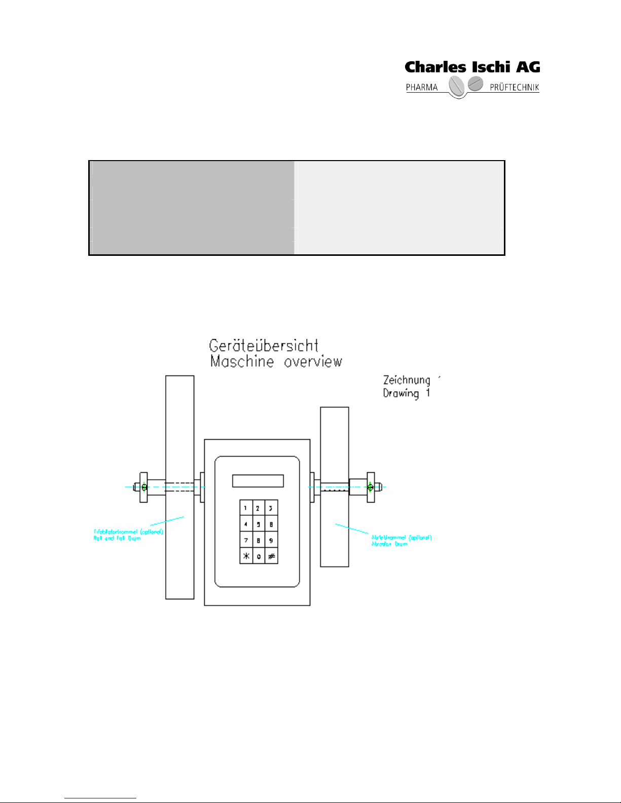
2.3. Load test drums
By removing the quick release nut either the drum lid or the complete drum can be
removed from the machine. The tablets are loaded into the test drum and the drum
is held in place on the shaft by means of the quick release nut. The test drum is correctly
mounted and closed when the quick release nut snaps into the groove on the shaft.
2.4. Starting the test
Press # (START) button
The machine begins to test
The tester shows the residual time or number of rotations
2.5. Ending the test
At the end of the test time or total counts the machine stops. The preset time or number
of rotations will be restored.
The test can be stopped by the button # STOP or interrupted and be continued later at
any time, before the end of the testing time or number of rorations.
The preset parameters are retained in the machine when it is turned off by means of
a battery.

OME_306511 6
3. TECHNICAL DATA
Power connection 200-240V / 50-60Hz
Fuses 2x M1A/250V
Speed 10 –99 rpm
Preset time 1min –23h 59min
Number of rotations 10 –999999 r
Drums Friability drum
Abrasiondrum

OME_306511 7
4. FINAL ASSEMBLY CONTROL TEST
Each machine undergoes, as a minimum, a 12-hour final assembly control test prior to
delivery. During this test all machine functions are checked.

OME_306511 8
5. SERVICING
The servicing contains a periodical cleaning of the tester. There are no wearing parts. The
spare part list you can find under point 7.

OME_306511 9
6. TROUBLESHOOTING
Machine malfunctions should only be repaired by an authorized school trained technician. In
the case it is not possible to correct the malfunction, Charles Ischi AG,
or theresponsible representative should be contacted for repairs.

OME_306511 10
7. SPARE PART LIST
Description Art. no.
Base plate 310901
Cover 310902
Display complete 310903
Main board 310904
Front foil 310905
Display board 310906
Sensor speed 310907
Sensor rotations 310908
Motor 310909
Axis left 310910
Axis right 310911
Fixing / drum left 310912
Fixing / drum right 310913
Mortor holder 310914
Control system unit 310915

OME_306511 11
8. CE–CONFORMITY DECLARATION
Wir / We Charles Ischi AG
Langfeldstrasse 26
4528 Zuchwil
Schweiz / Switzerland
Erklären hiermit, in alleiniger Verantwortung, dass dieses Produkt,
Declare sole responsibility for our product,
Abriebs-und Friabilitäts-Testgerät
Abrasion-and Friability Tester
Typ AE-1
Auf die sich diese Erklärung bezieht, die Normen und normativen Dokumente der
EG-Richtlinien für Maschinen 89/392/EWG berücksichtigt wurden.
To which this declaration document relates is in conformity with the standardsand
norms for machines of the EC.
Zuchwil, 28.04.2004 ......................................................
Ort, Datum rechtsverbindliche Unterschrift
Place, Date Signature

OME_306511 12
9. DECLARATION OF CONFORMITYWITH PH-EUR5.0/2005 AND USP29 NF2006
Wir / We Charles Ischi AG
Langfeldstrasse 26
CH-4528 Zuchwil
Switzerland
Erklären hiermit, in alleiniger Verantwortung, dass dieses Produkt,
Declare sole responsibility for our product,
Abriebs-und Friabilitäts-Testgerät
Abrasion-andFriabilityTester
Typ AE-1
mit den Anforderungen der European Pharmacopoeia 2005 und USP29 NF2006
übereinstimmt, soweit diese für Abriebs-und Friabilitäts-Testgeräte anwendbar sind.
is conform with the requirements of the European Pharmacopoeia 2005 and USP29
NF2006, concerning the regulations forAbrasion-and Friability Testing.
Zuchwil, 14.11.2006......................................................
Ort, Datum rechtsverbindliche Unterschrift
Place, Date Signature
OME_306511 13
10.DRAWINGS
Drawing no.
1Machine overview
2Rear panel

OME_306511 14

OME_306511 15
11. TECHNICAL INFORMATION –Install support 10° angle
Machine with angle 10° angle with screw
Take out one of thesetwo screws left or Use the screw which we deliver with this
right and put on this place the 10° angle.angle, see on the picture in which
position you have to fasten the angle.
Table of contents
Popular Test Equipment manuals by other brands

Global Specialties
Global Specialties 3600 user manual

Tektronix
Tektronix TDS3000C Series Declassification and security instructions

Bante Instruments
Bante Instruments PHscan20S/F instruction manual

JDS Uniphase
JDS Uniphase Validator quick start guide

Fluke
Fluke 718Ex 300G Specifications

Reely
Reely 206964 operating instructions

HeartSciences
HeartSciences MyoVista Quick reference user guide

Valen
Valen RE856 Operation manual

Polar Instruments
Polar Instruments T1500A Operator's manual

Sonotec
Sonotec SONAPHONE E operating instructions

pico Technology
pico Technology ADC-100 user guide

Keysight Technologies
Keysight Technologies U2941A operating guide


