Sonotec SONAPHONE E User manual

Ultrasonic Testing Device
SONAPHONE E
Operating Instructions

OM_SONAPHONE_E_en_Rev_2.3_2018-07-19 page 2
Manufacturer: SONOTEC Ultraschallsensorik Halle GmbH
Model: Ultrasonic Testing Device
Type: SONAPHONE E
SONOTEC Ultraschallsensorik Halle GmbH
Nauendorfer Str. 2
06112 Halle (Saale), Germany
Telephone: +49 (0) 345 13317-0
Fax: +49 (0) 345 13317-99
E-mail: sonotec@sonotec.de
Internet: www.sonotec.eu
© 2016
SONOTEC Ultraschallsensorik Halle GmbH
All rights reserved
The content of this operating manual is property of SONOTEC
Ultraschallsensorik Halle GmbH and protected by copyright. No part of
this manual may be translated, copied or reprinted without the explicit
written consent of SONOTEC Ultraschallsensorik Halle GmbH.
Revision: 2.3 Date: 2018-07-19

OM_SONAPHONE_E_en_Rev_2.3_2018-07-19 page 3
Table of Content
1Safety precautions..................................................5
1.1 Special safety precautions on the use of the
SONAPHONE E in hazardous areas...............................5
1.2 Safety precautions for the SONAPHONE E in
hazardous areas..............................................................6
1.3 General safety precautions for the SONAPHONE E........8
2Scope of delivery ....................................................9
2.1 Summary.........................................................................9
2.2 Arrangement of devices and accessories in the
transport case ...............................................................10
3Function description.............................................11
3.1 General information.......................................................11
3.2 SONAPHONE E connections, control- and display
elements........................................................................12
4Operation...............................................................13
4.1 Insert the batteries.........................................................13
4.2 Starting up the unit........................................................16
4.3 Battery status indicator..................................................16
4.4 Check mode..................................................................17
4.5 Main menu ....................................................................20
4.6 Data logger....................................................................21
4.7 Test parameters............................................................29
4.8 Settings.........................................................................31
5Using the probes...................................................33
5.1 Air-borne sound probe L60............................................33
5.2 Structure-borne sound probe L61 for valve inspection
(oil and water resistant).................................................34
5.3 Structure-borne sound probe L62 for long-time tests
and detection of bearing wear .......................................35
5.4 Flexible air-borne sound probe L63...............................36
6Using accessories.................................................37
6.1 Telescoping rod.............................................................37
6.2 Surface temperature sensor..........................................38
6.3 Using the grounding set.................................................39

OM_SONAPHONE_E_en_Rev_2.3_2018-07-19 page 4
7PC connection & data transfer.............................40
7.1 Directory structure of the installation CD .......................41
7.2 Installation for Windows XP / Windows Vista.................41
7.3 Installation for Windows 7..............................................43
7.4 Power supply via USB...................................................45
8Trouble shooting...................................................46
9Technical specifications.......................................47
10 Warranty ................................................................48

OM_SONAPHONE_E_en_Rev_2.3_2018-07-19 page 5
1 Safety precautions
1.1 Special safety precautions on the use of the
SONAPHONE E in hazardous areas
(1) Change batteries only outside hazardous areas.
(2) Exclusively the following alkaline primary cells are approved for the
use:
•Varta High Energy 4906 MN1500
•Duracell Plus MN1500
(3) The permissible range of operating temperatures for the
SONAPHONE E and the probes is 0 °C … +40 °C.
(4) Only the accessories included are allowed to be attached to the
SONAPHONE E: headphones, surface temperature sensor, ultrasonic
probes, probe accessories, telescoping rod and extra sensor.
(5) The ultrasonic transmitter SONAPHONE T (optional accessory) is
not an explosion-protected device, and must not be taken into or
operated in an hazardous area!
(6) Do not take the carrying case into the hazardous area!
(7) Only the ultrasonic probes L60 and L61 in connection with the probe
extension cable are intended for the use in Ex-zone 0. The
SONAPHONE E and the other accessories must not be taken into Ex-
zone 0.
(8) Only the equipment offered by SONOTEC as accessories may be
used as extra sensors. If the extra sensor is connected, the complete
set of equipment may only be operated in Zone 1 and 2. (protection
level drops to “ib”).
(9) Connect the SONAPHONE E exclusively to normal commercial
devices with a maximum voltage of 60 V using a USB cable. This is only
ensured for equipment labelled with the CE mark. Connect and operate
the USB interface only outside hazardous areas.
OM_SONAPHONE_E_en_Rev_2.3_2018-07-19 page 6
1.2 Safety precautions for the SONAPHONE E in hazardous
areas
The SONAPHONE E conforms to the best available technology and
safety rules. The manufacturer has made every effort to ensure safe
operation. The user must make sure that its safe use is not affected.
The device has been tested in the factory and was delivered in a safe
operating condition.
(1) The device may only be used by persons instructed with its use. All
users who work with this device must read these operating instructions
first.
(2) The SONAPHONE E is intended for the use in areas in which there
is a danger of explosion due to gases, vapours or mist accordance to
the device marking. Do not use the device where there is a danger of
dust explosions.
SONAPHONE E
II2G Ex ia IIC T4 Gb
The SONAPHONE E, the surface temperature sensor and the
headphones conform to EPL (Equipment protection level) b.
Ultrasonic probes L60, L61, L62 and L63
II2G Ex ia IIC T4 Gb
Ultrasonic probes L60 and L61
II1G Ex ia IIB T4 Ga and II2G Ex ia IIC T4 Gb
The ultrasonic probes L60, L61, L62 and L63 conform to EPL
(Equipment protection level) b for gas group IIC, IIB and IIA.
Furthermore, the ultrasonic probes L60 and L61 conform to EPL
(Equipment protection level) a for gas groups IIB and IIA. The ultrasonic
probes L60 and L61 may be taken into Ex-zone 0 (only for gas groups IIA
and IIB). However, the permanent installation of these probes in Ex-zone 0
is not permitted.
Code for marking explosion protected devices:
Equipment group
II (aboveground applications)
Category group
2 (high safety, suitable for Ex-Zones 1 and 2)
1 (very high security, suitable for Ex-Zones 0, 1 and 2)
Atmosphere
G (gas, dust, vapours)
Type of protection
ia (intrinsic safety)
Gas group
IIA (less ignitable) ··· IIB ··· IIC (easy to ignite)
Temperature class
T4 Minimum ignition temperature of the atmosphere 135°C
EPL (Equipment
protection level) Explosive gas atmosphere areas: Ga (Zone 0) / Gb (Zone 1)

OM_SONAPHONE_E_en_Rev_2.3_2018-07-19 page 7
Local equipotential equalisation may only be done with the earthing set
available from SONOTEC Ultraschallsensorik Halle GmbH. Please see the
chapter 0 for instructions of the use of the earthing set.
As the probes are made of a light metal alloy, avoid friction and impact
sparks which can result from dropping the probes.
(3) The device is suitable for measuring surface temperatures up to
800 °C. Such high temperatures are only encountered outside
hazardous areas.
(4) The SONAPHONE E is not authorized for the use in mines
susceptible to firedamp.
(5) The SONAPHONE E must be protected against moisture
penetration.
(6) Ensure that electrostatic charges do not build up on the plastic parts.
Carrying cases, grips, probe accessories, cables and objects coated in
plastic must not be rubbed against one another or against other objects.
Use a damp cloth to clean the unit and all accessories. Aggressive
cleansers may attack the SONAPHONE E’s plastic casing and affect its
mechanical stability.
(7) You are not allowed to open the SONAPHONE E or its accessories
or to perform any unauthorised repairs. This could affect the explosion
protection. Repairs may only be carried out by the manufacturer.

OM_SONAPHONE_E_en_Rev_2.3_2018-07-19 page 8
1.3 General safety precautions for the SONAPHONE E
(1) The SONAPHONE E and the probes are suitable for the use at
temperatures between 0 and 40 °C. Store the unit at temperatures
between -10 °C and +50 °C.
(2) Make sure that you have a clear view of the SONAPHONE E and the
probes at any time of operation. Never work with the probes or the
telescoping rod in areas with live parts or areas you do not know
exactly. When locating ultrasonic signals in electrical installations, keep
a sufficient safety distance to prevent electrical flashover.
(3) Always handle the probe for structure-borne ultrasound with care, so
that the probe tip does not cause any injuries. Use the probe carrier bag
on the shoulder strap when carrying it outside the carrying case or when
the probe is not in use.
(4) Use the shoulder strap on stairs, ladders, platforms etc. so that you
can have your hands free to brace yourself.
(5) Avoid using the SONAPHONE E in strong electromagnetic fields.
(6) The SONAPHONE E is a testing device.
(7) SONOTEC Ultraschallsensorik Halle GmbH offers no warranty for
damages, even for harm to third parties, caused by incorrect handling of
the device.
(8) The SONAPHONE E, the probes and all accessories have a robust
casing. However, they must be protected from mechanical damage and
sharp impacts. Do not use cleansers containing solvents.

OM_SONAPHONE_E_en_Rev_2.3_2018-07-19 page 9
2 Scope of delivery
2.1 Summary
SONAPHONE E testing device
Probes*
• Air-borne sound probe L60
• Structure-borne sound probe L61
• Structure-borne sound probe L62 with stainless steel tip
• Flexible air-borne sound probe L63
Accessories*
• Headphones (with high sound insulation)
• Surface temperature sensor (Tmax = 800 °C)
• Probe extension cable 30 cm
• Extension cable for the surface temperature sensor
• Directional tube with tip
• Acoustic horn (attachment for airborne sound probe L60)
• SONAPHONE T ultrasonic transmitter
• Spherical transmitter SONOSPHERE
• Aluminum telescope bar
• Transport case
• PC software SONAPHONE E Communicator
• USB cable
• Operating instructions
• Grounding set for probes L60 and L61
*) Please do notice, that the scope of delivery varies according to your
order.
OM_SONAPHONE_E_en_Rev_2.3_2018-07-19 page 10
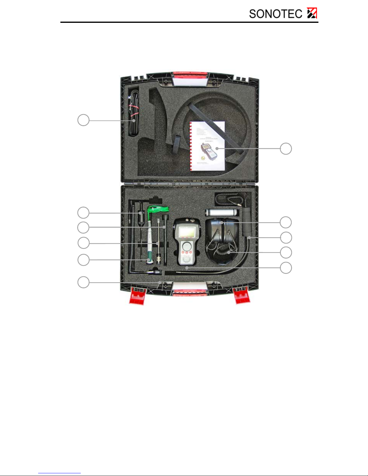
2.2 Arrangement of devices and accessories in the
transport case
1 Shoulder strap
2 Structure-borne sound probe
L62
3 Directional tube with tip
4 Surface temperature sensor
5 Extension cable for the
temperature sensor
6 Air-borne sound probe L60
with probe extension cable
7 Operating instructions
8 SONAPHONE T
9 Flexible air-borne sound probe
L63
10 Headphones
11 SONAPHONE E
1
2
3
4
5
6
7
8
9
10
11

OM_SONAPHONE_E_en_Rev_2.3_2018-07-19 page 11
3 Function description
3.1 General information
Ultrasound is generated due to friction caused by the flow of gases,
liquids and solids in pipes and leakages. These ultrasonic signals are
recorded by the SONAPHONE E, their intensity is shown on the display
screen and made audible through speaker or headphones. As an
option, surface temperatures can be measured with a temperature
sensor. The recorded data can be stored and transmitted to a personal
computer using the integrated USB interface. Ultrasound can be
generated in a wide variety of processes, for example:
• at leaks in compressed air-, steam- and vacuum systems
• at steam traps
• at leaky valves, gate valves, shut-offs and valves in pipings
• from roller bearing damages
• from cavitation at pumps and compressors
• from flash-overs and corona discharges on electrical installations
Using the SONAPHONE E, it is possible to locate precisely the defects
and estimate their magnitude. The ultrasonic transmitter
SONAPHONE T (optional accessory) can be used to detect leaks in
vehicles, freight containers, other types of containers and ventilation
technique systems where no ultrasound is generated. The
SONAPHONE T generates ultrasonic waves which emerge at the leaks.
Precise location is carried out from the outside with the
SONAPHONE E.
CAUTION!
The ultrasonic transmitter SONAPHONE T (optional accessory) must
not be taken into or operated in hazardous areas!
The SONAPHONE E tester is a mobile hand-held and battery-supplied
unit. Various probes, which are connected directly or via a cable to the
tester, serve to detect the ultrasound. The type of probe is automatically
recognised by the SONAPHONE E by means of a probe code. A
surface temperature sensor (type K thermocouple, NiCr-Ni) with a
circular plug-in connector is used for temperature values (optional). It
can be extended at any time using a corresponding extension cable.
OM_SONAPHONE_E_en_Rev_2.3_2018-07-19 page 12
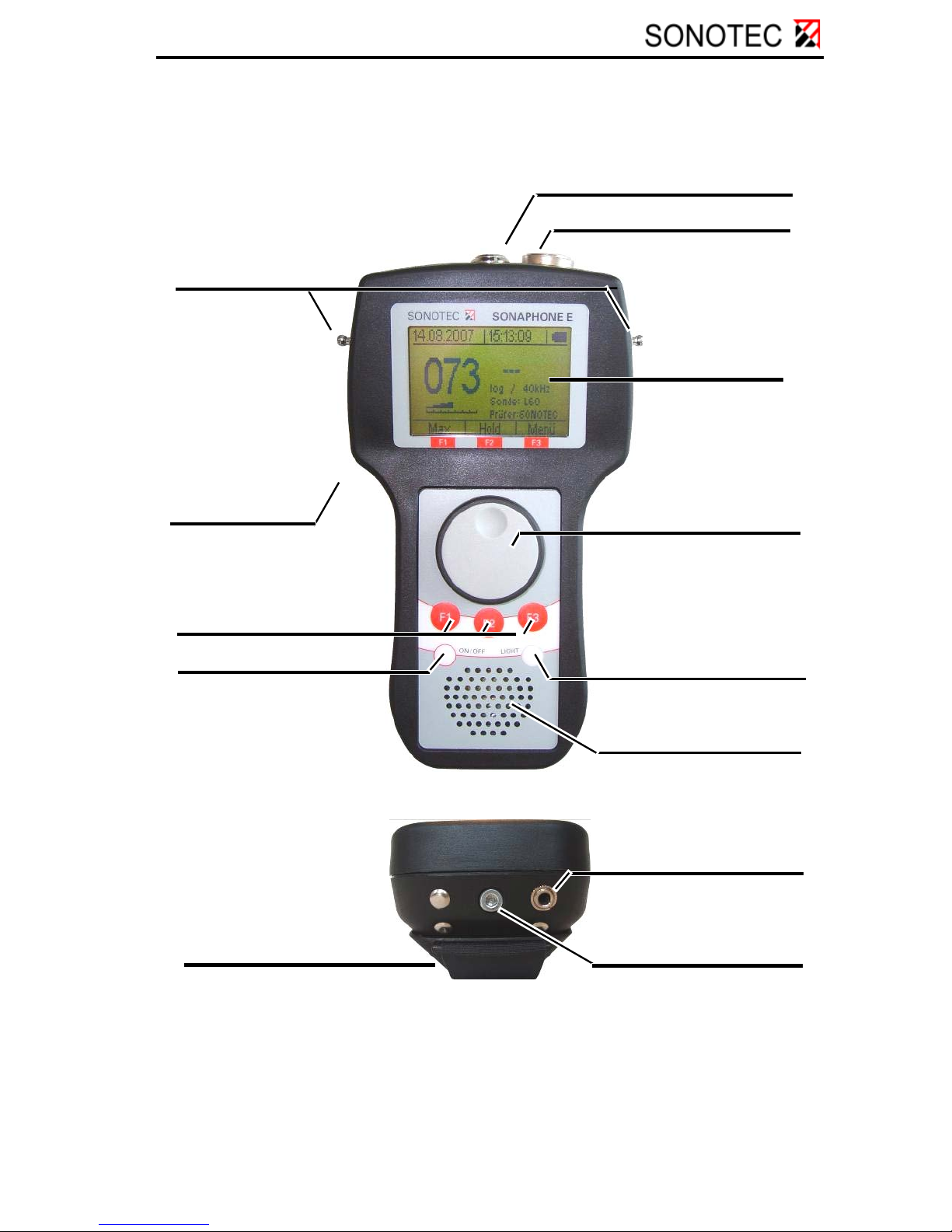
3.2 SONAPHONE E connections, control- and display
elements
Battery compartment lid
USB interface
ON/OFF button
Function buttons „F1-F3“
Ultrasonic-probe connector
Fastener for carrying
shoulder strap
Surface temperature sensor
connector
Graphical
display
Rotary knob with
integrated push button
LIGHT button
Integrated
speaker
Headphone connector
Screw for releasing the
battery compartment lid
OM_SONAPHONE_E_en_Rev_2.3_2018-07-19 page 13
4 Operation
4.1 Insert the batteries
Safety notes
•Only the batteries listed in Section 1.1 may be used for
operation in hazardous areas.
- Varta High Energy 4906 MN15001
- Duracell Plus MN15001
•The batteries should only be changed when the device is
switched off.
•When opening the battery compartment lid, do not have the
device connected to a PC through a USB cable.
•When inserting the batteries, make sure the polarity
corresponds to the engraved marking on the battery block.
•Follow the instructions below!
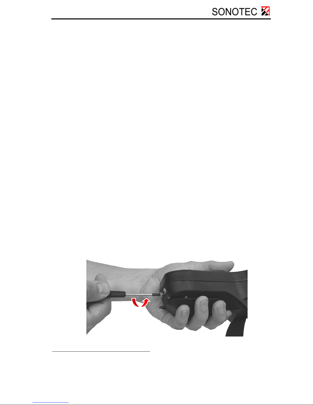
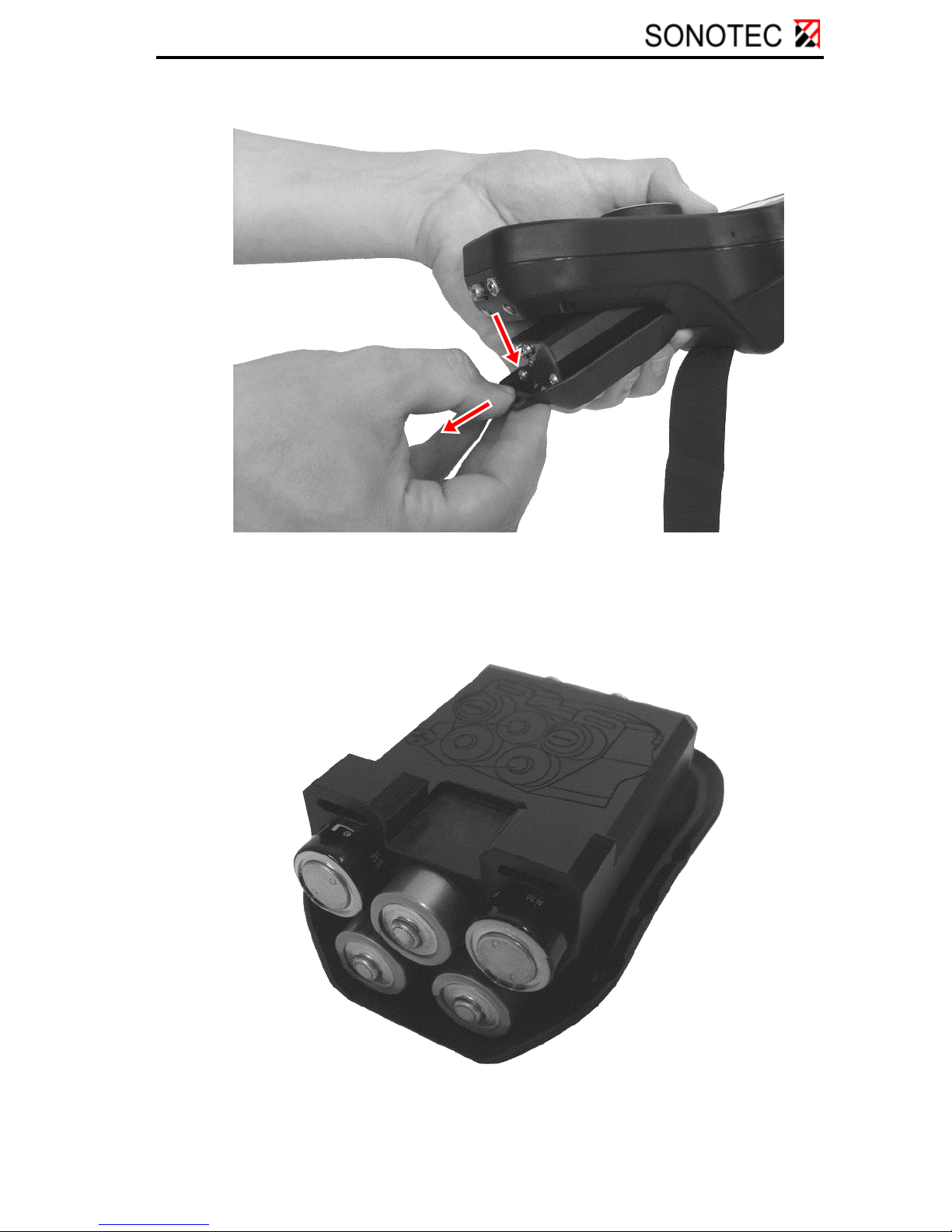
Description of the battery change
1. Disconnect the shoulder strap from the battery compartment lid.
2. Turn back the locking screw of the battery compartment all the
way until it stops. The battery block will move in the same
direction as the locking screw. It is important to hold the battery
block and the device firmly.
1Please contact SONOTEC in case the batteries are not available.
OM_SONAPHONE_E_en_Rev_2.3_2018-07-19 page 14
3. Press down the battery compartment and pull it out of the unit.
4. Take the batteries out of the battery block.
5. Insert new batteries into the block, checking that the polarity is
correct. An engraving on the top of the battery block illustrates
the correct arrangement of the batteries.

OM_SONAPHONE_E_en_Rev_2.3_2018-07-19 page 15
6. Re-insert the battery compartment into the casing.
7. Tighten the locking screw of the battery compartment again.
8. Fasten the shoulder strap to the battery compartment lid.

OM_SONAPHONE_E_en_Rev_2.3_2018-07-19 page 16
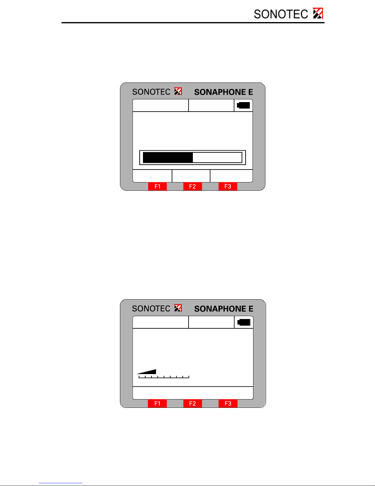
4.2 Starting up the unit
The device is switched on by pressing the ON/OFF button. After
displaying the splash screen, it switches automatically to the testing
mode. The following is shown on the display:
16.02.2007
Max Hold Menu
046
11:24:58
log / 40kHz
Sensor: L60
Tester: SONOTEC
20°C
1Battery or USB operation
battery status indicator
2Temperature
3Testing mode / mixer
frequency
4Type of probe
5Tester
6 Currently available functions
of keys “F1-F3”
7 Intensity bar for ultrasonic
test value
8 Ultrasonic test value
9 Date / time
4.3 Battery status indicator
The symbol (labelled ’1’ in the above illustration) at the top right edge of
the display provides information about the status of the batteries in the
unit and about the kind of power supply:
Battery operation (about 60%)
USB operation
2
1
3
4
5
9
8
7
6

OM_SONAPHONE_E_en_Rev_2.3_2018-07-19 page 17
4.4 Check mode
Control elements
Turning the rotary knob: Volume adjustment
Pressing the rotary knob: Storing the test values
(see Section: Single test)
F1 (Max): Turns on or off "Max“ function
F2 (Hold): Turns on or off "Hold“ function
F3 (Menu): Switch to menu in order to adjust the
settings of the unit
“LIGHT“: Controls the display lighting
(Off – Level I – Level II – Level I – Off)
To switch the unit on or off press the ON/OFF button. Depending on the
intended use, connect the appropriate probe or the temperature sensor
to the SONAPHONE E (see Section: Using the probes).
A probe for structure-borne ultrasound is used for locating leaks. The
level of ultrasound is besides the magnitude of the sound source also
dependent on the probe’s direction and distance from the sound source.
This effect can be used to locate and evaluate leaks. If no probe is
plugged into the unit, the message “No Probe” is displayed instead of
the ultrasound level.
OM_SONAPHONE_E_en_Rev_2.3_2018-07-19 page 18
Volume adjustment
When the rotary knob is turned, a volume bar and an intensity value are
displayed for about two seconds, as shown below:
046
16.02.2007 11:24:58
20°C
Volume -24dB
Turning the rotary knob clockwise increases the volume and turning it
anti-clockwise decreases the volume.
Storing the test values
When the rotary knob is pressed in the check mode (provided that at
least one Single test has been prepared), the ultrasonic test values and
the current temperature are stored in the individual test selected as
“Active”. During this process, “Save” and the name of the single test
appear briefly on the display:
16.02.2007
046
11:24:58
log / 40kHz
Sensor: L60
Tester: SONOTEC
20°C
Save: Pumpe1
OM_SONAPHONE_E_en_Rev_2.3_2018-07-19 page 19
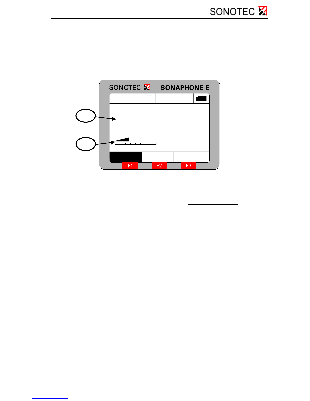
“Max“ function
The F1 key activates the “Max” function. In this state, the number
displayed corresponds to the maximum ultrasound level and the
intensity bar to the current ultrasound level. The activation of the “Max”
function is signalled by highlighting the function key description:
16.02.2007
Max Hold Menu
046
11:24:58
log / 40kHz
Sensor: L60
Tester: SONOTEC
20°C
1 Maximum ultrasound level
2 Current ultrasound level
Pressing the rotary knob, stores the currently displayed value, in other
words the maximum value, in the individual test that is active.
Press the „F1” function key again to deactivate the “Max” function.
"Hold“ function
Press the F2 function key to activate the “Hold” function. This serves to
register ultrasound levels, for example, if the display is not visible at the
moment of testing. Thereby, the ultrasound level, which was recorded at
the moment the F2 key was pressed, is stored in the display.
1
2

OM_SONAPHONE_E_en_Rev_2.3_2018-07-19 page 20
16.02.2007
Max Hold Menu
046
11:24:58
log / 40kHz
Sensor: L60
Tester: SONOTEC
20°C
Press the rotary knob to store the currently displayed value, in other
words the “Hold” value, in the individual test that is active.
Press the F2 key again to deactivate the “Hold” function.
4.5 Main menu
Menu structure
Data Logger (1)
Test Parameter (2)
Setup (3)
Single test (1) Averaging time (1) Date/Time (1)
Tester (2) Auto-Power-Off (2)
Long-time test (2) Mixer Frequency (3) Auto-Light-Off (3)
Mode (4) Contrast (4)
Temperature (5) Language (5)
Operation
There is a choice of three menu items in the main menu: the data logger
for storing the test values, the test parameters for changing all
parameters relevant to the test and the setup for changing the device’s
parameters. The selection is carried out by turning the rotary knob.
Press it to open the respective menu. Press the F3 function key to
return the unit to the check mode.
Other manuals for SONAPHONE E
1
Table of contents
Other Sonotec Test Equipment manuals

Sonotec
Sonotec Airborne Sound Sensor BS10 Operator's manual

Sonotec
Sonotec SONO-PR 200 User manual

Sonotec
Sonotec SONAPHONE E User manual

Sonotec
Sonotec Sonaphone Pocket User manual

Sonotec
Sonotec SONASCREEN User manual

Sonotec
Sonotec Sonaphone Operator's manual

Sonotec
Sonotec Sonaphone User manual

Sonotec
Sonotec Sonaphone Manual

Sonotec
Sonotec Sonaphone Manual


