Charles FSDC-H Series Operating and installation instructions
LT-FSDC-H
1st Printing, November 26, 2019
©Copyright 2019 Charles Industries LLC. All Rights reserved. Printed in the United States of America.
Availability of features and technical specifications herein are subject to change without notice.
Charles is a registered trademark of Charles Industries.
Page 1 of 11
Charles Fiber Sealed Drop Closure
FSDC-H Series
General Description and Installation
1. GENERALINTRODUCTION.............................................................................................1
1.1 Document Purpose..............................................................................1
1.2 Product Purpose .................................................................................1
1.3 Product Mounting and Location........................................................1
2. PRODUCTDESCRIPTION...................................................................................................1
3. SAFETYPRECAUTIONS......................................................................................................2
4. INSTALLATION.........................................................................................................................3
4.1 Route Express Cable Loop into Closure ...........................................3
4.2 Route and Splice Fiber Inside Closure..............................................5
4.3 Closing the FSDC ...............................................................................7
4.4 Connecting Hardened Drops.............................................................8
4.5 Mounting the Closure.........................................................................9
5. TECHNICALASSISTANCEANDREPAIRSERVICE......................................11
6. MODELNUMBERINFORMATION...........................................................................11
1. GENERAL INTRODUCTION
1.1 Document Purpose
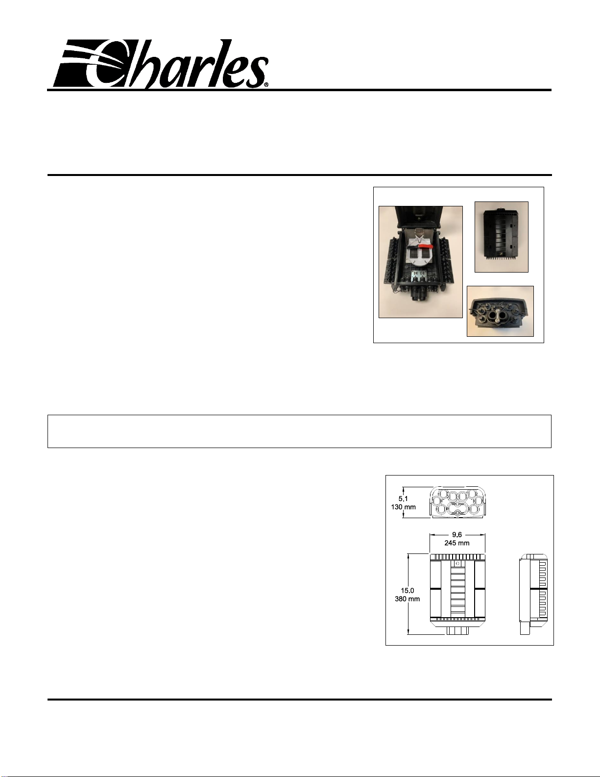
This document provides installation instructions for the Charles Fiber Sealed Drop Closure for hardened connectorized assemblies (FSDC-
H). A typical FSDC-H is shown in Figure 1.
-NOTE-
Hereafter the Charles Fiber Sealed Drop Closure Series will be referred to as the “FSDC-H” or “closure.”
1.2 Product Purpose
The FSDC-H a sealed splice closure (IP68 rated) used in fiber splicing applications where a
single feed fiber must be split into multiple drop connections.
1.3 Product Mounting and Location
The FSDC-H can be aerial strand mounted, pole mounted, or wall mounted. Mounting
brackets are sold separately. The FSDC-H is a sealed unit that can also be used in a hand-
hole or in a pedestal.
2. PRODUCT DESCRIPTION
The FSDC-H is a closure that allows splicing operations between feed and drop fibers.
Some models include splicing trays, and with others the trays are purchased separately
(Table 1). The tray can be equipped with an optical tap or a fiber splitter, which allows a
single feed signal to be split into multiple drop signals.
The FSDC-H is designed for quick plug-and-play subscriber additions. The units have eight
hardened Amphenol-H connectors to SC/APC adapters on the front face. These connectors
accept OptiTap ® and OptiTap compatible hardened connector assemblies.
The FSDC-H dimensions are shown in Figure 2. The FSDC-H ships with a number of tools
and accessories, shown in Figure 3.
Figure 2 FSDC-H Dimensions
Figure 1 FSDC-H

LT-FSDC-H
Page 2 of 11
1st Printing
3. SAFETY PRECAUTIONS
—WARNING—
Risk of serious eye damage! Never look into the end of a fiber optic line or use a magnifier in the presence of laser light or radiation.
Exercise caution when installing, testing or maintaining live circuits. If eyes are exposed to laser light or radiation occurs,
immediately seek treatment by a medical professional.
—WARNING —
Cable and fiber cleaning solvents may contain hazardous or harmful materials. Maintain good housekeeping practices and refer to
the MSDS when working with cleaning solvents or similar products.
Shards and cleaved glass fibers are very sharp and can easily pierce the skin. Use tweezers to pick up cut glass fibers and place
them in a specifically designated container. Do not consume any food products near the cable installation site.
Corrugated metal or armor in feed cables is very sharp when cut or exposed. Exercise extreme caution to prevent personal injury.
Use protective work gloves when handling armored cable.
—CAUTION —
Perform all bonding and grounding prior to making any electrical and communications connections.
Be careful not to damage any buried cables or service wires while digging either to expose cables or to prepare a hole or trench, or
while driving stakes. Buffer tubes and fibers are sensitive to excessive bending, pulling, and crushing forces. To avoid kinking of
buffer tubes and fiber damage or breakage, exercise great care when working with fiber, and do not exceed or violate minimum
bend radius requirements for fibers, buffer tubes, and cables.
Figure 3 Tools and Accessories

LT-FSDC-H
1st Printing
Page 3 of 11
4. INSTALLATION
Gather the following equipment to perform the FSDC-H installation.
Philips and flathead screwdrivers
5 mm (or 3/16”) Allen wrench
Measuring tape
Cable marking tool
Assorted cable ties
Accessories kit (provided with the FSDC-H)
Knife or snips (to cut grommets)
Buffer tube stripper tool (score/cut buffer tubes)
Fiber optic stripper tool
Fiber splicing tools and equipment
Safety glasses and work gloves
4.1 Route Express Cable Loop into Closure
Step
Number
Instruction
1
Use theincluded Allen wrench or any 5mm or 3/16 Allen wrench to
loosen the two security screws near the bottom corners of the FSDC-H.
Use a flathead screwdriver to pry open the four hinged latches that
hold the FSDC-H closed.
Note: The accessory bag includes a closure cover stop, which can be
placed in the door hinge to hold the door securely open.
2
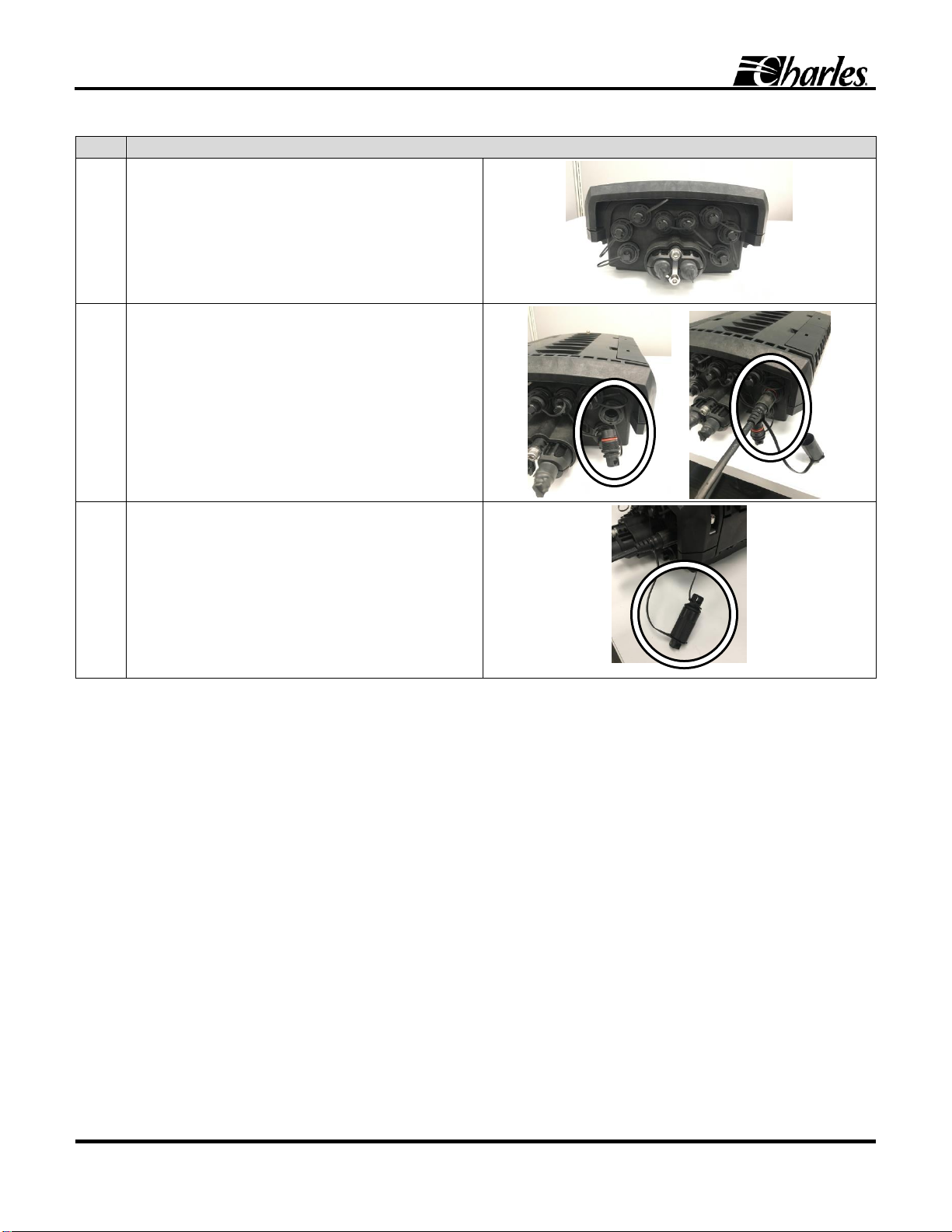
Locate the express port (oval port) on the
bottom of the FSDC. Use a 5 mm (or 3/16”)
Allen wrench to remove the sealing
components.
Note: The express port can accommodate
cable with OD from 10 to 17.5 mm (0.394 to
0.689 inches).
Select the proper size rubber gasket from the
accessory kit based on the fiber cable
diameter. Use the smaller rubber gasket for
cables 10 to 12mm outer diameter and the
larger rubber gasket for cables 12.5 to
17.5mm.
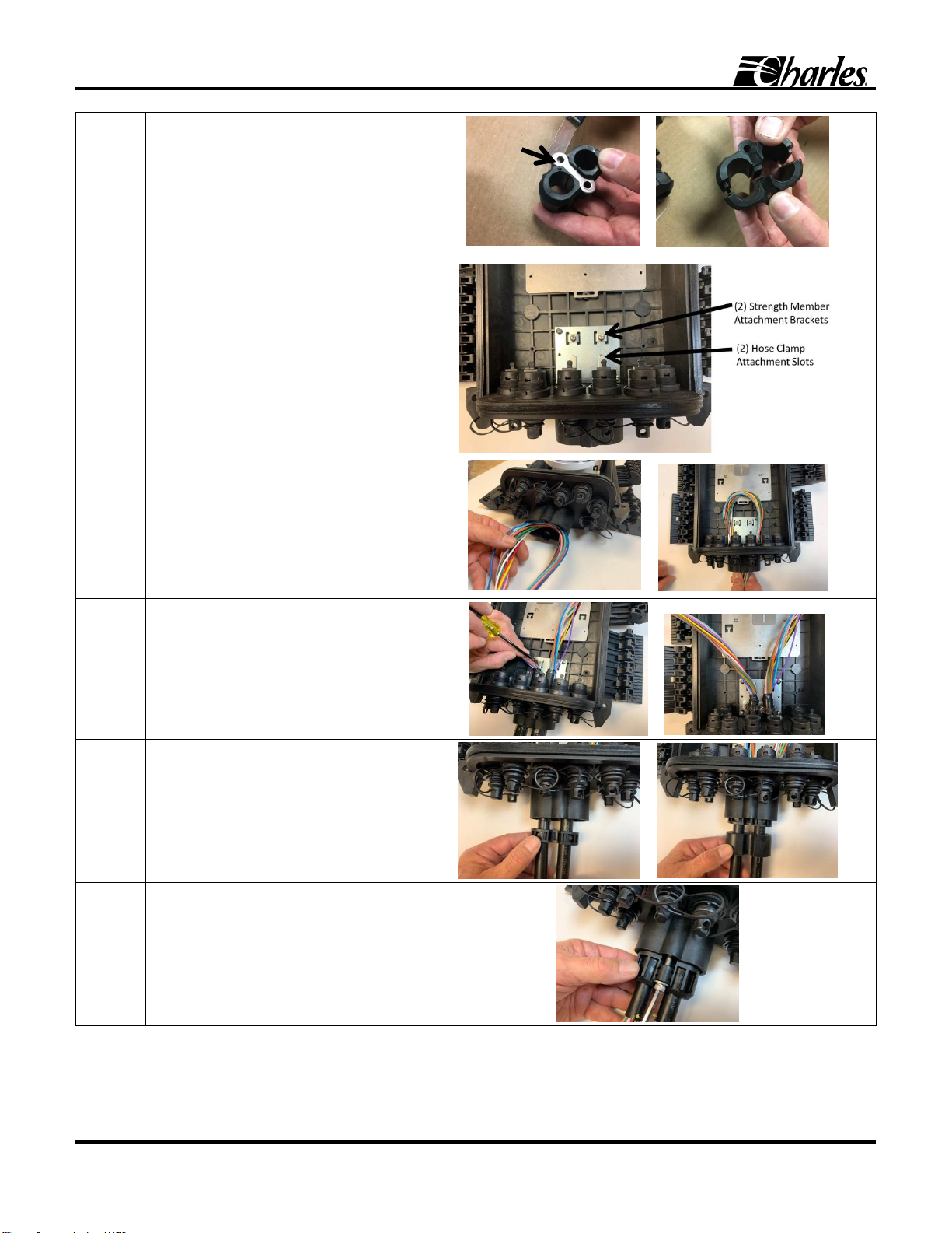
3
Slit the rubber middle gasket apart on the
outsides.
Separate the pieces of the plastic inner
gasket.
Set these gaskets aside for later use.
LT-FSDC-H
Page 4 of 11
1st Printing
4
Remove and set aside the screws from the
plastic outer gasket.
Remove and set aside the metal compression
plate that seals the express loop plug in the
port.
Disassemble and set aside the plastic outer
gasket and set the components aside.
5
Locate the attachment plate in the FSDC-H
closure.
There are two brackets for securing a strength
member and two slots for attaching a hose
clamp.
6
Obtain a cable and remove the sheath from a
6.5 to 7.0 foot (max. 7.0 ft.) section. Cut the
strength member to a 2.5 to 3.0”length on
both sides of the unsheathed section.
Discard sheathing and scrap strength member
according to local practice.
Push and feed a 6.5 to 7.0 foot (max. 7.0 ft.)
length of unsheathed cable into the express
loop-through hole.
7
Guide the strength members on each side of
the cable loop under the clamps, using a
Philips screwdriver to tighten the clamps in
place.
Use a 6 mm hose clamp on each cable to
secure in place (clamps included in the
accessory bag).
8
Take the previously removed plastic inner
gasket and connect the pieces around the
sheathed cables. Push this grommet inward
into the express loop port.
Fit the rubber middle gasket around the
cables. Push this gasket inward into the
express loop port.
9
Reassemble the previously removed plastic
outer gasket around the cables.
Put the previously removed metal
compression plate back in place and retrieve
the express port screws. Use the 5 mm (or
3/16”) Allen wrench to secure the express port
sealing components together in the express
loop port.
Compression
Plate
LT-FSDC-H
1st Printing
Page 5 of 11
4.2 Route and Splice Fiber Inside Closure
The FSDC-H can accommodate a number of fiber architectures including splitters, optical taps, or fanout/pigtails.
Charles offers splitter trays and optical tap trays. Splitters are available in 1x2, 1x4, or 1x8 configurations and come in 4” x 6” Charles
splice trays. Alternatively, if preferred, the user may install a loose PLC splitter into a Charles splice tray. Select splitters with SC/APC
connector output. Charles optical tap trays are only available in the longer 4” x9” splice tray. If using the 4” x 9” splice tray, it must be
installed in the top position on the hinged bracket.
When a splitter is installed in the FSDC, route a single buffer tube into the tray. Select a single fiber from this buffer tube to splice to the
splitter or tap input (white) fiber. Generally, this input fiber enters the tray on the left side. Use a connectorized splitter to connect the
output legs of the splitter or the drop legs of the tap by plugging the connector into the SC adapter side of the hardened adapters inside the
closure.
These closures can also be used with direct connection fanout or pigtails kits. The fanout or pigtail kits are not included and must be
ordered separately.
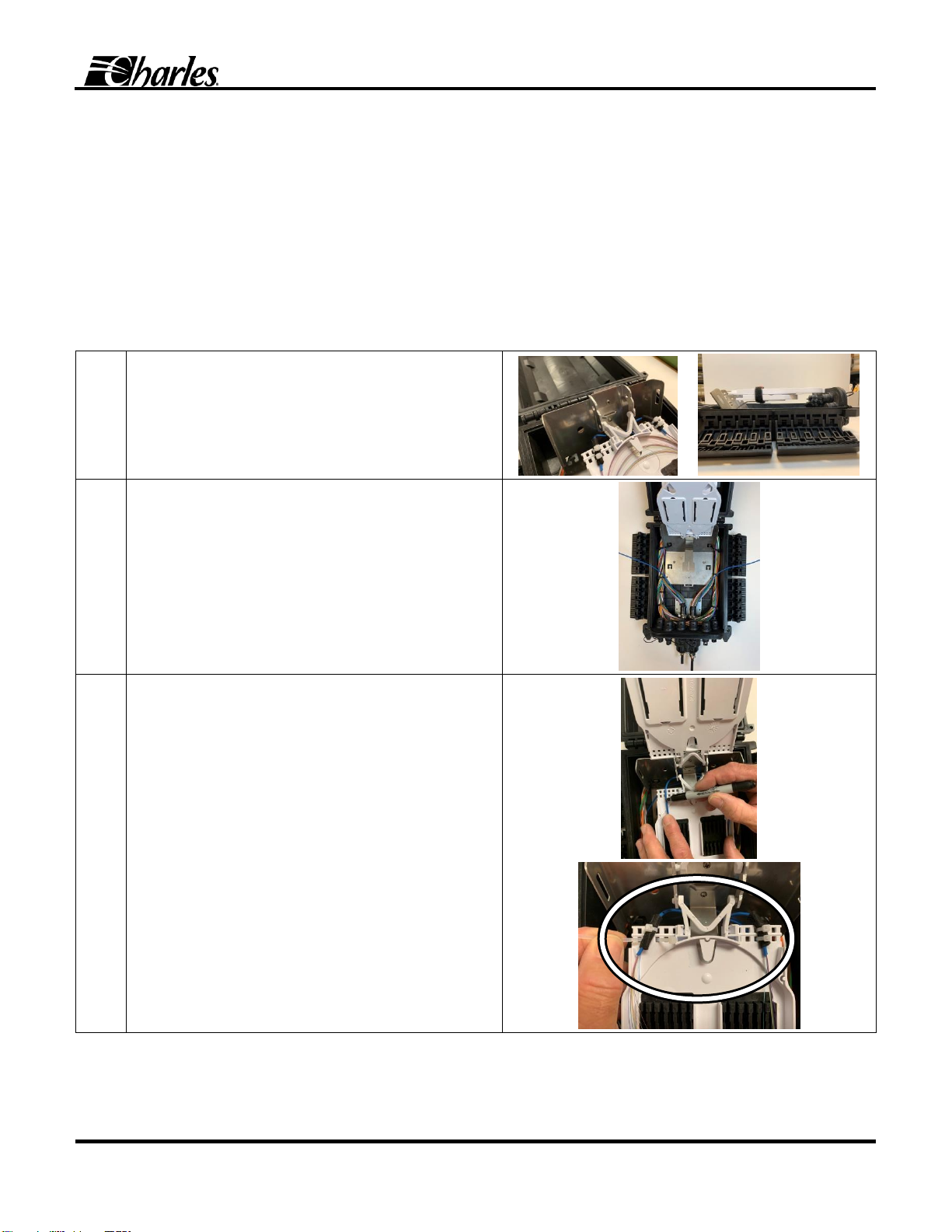
1
The FSDC-H can accept either:
One long (4”x9”) splice tray in the top position and one
short (4”x6”) splice tray in the bottom position OR
Two short (4”x6”) splice trays.
Attach trays to the hinge bracket.
If using a long tray (second image), then it must be attached at
the top position on the hinge.
2
Route buffer tube in the basket underneath the trays. Buffer
tubes must pass under the hinge bracket to avoid kinking.
Tie down as needed using cable ties to ensure that no buffer
tubes will get pinched in the door hinge when the FSDC-H is
closed.
3
Mark the point where the buffer tube will enter and exit the tray
using a permanent marker.
Strip the buffer tube sheathing between these two points to
expose the fibers.
Secure the buffer tube at its entry and exit points using customer
supplied felt and cable ties.
Ensure that the cable ties are positioned over the ends of the
buffer tube sheathing, not over bare fibers.
LT-FSDC-H
Page 6 of 11
1st Printing
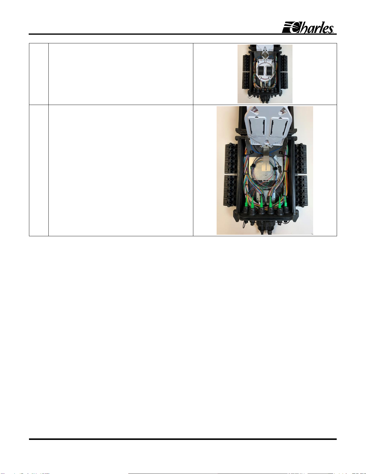
4
Coil and route fibers inside the tray.
5
Locate the connectorized fanouts that come with the FSDC.
Plug the connectors into the ports on the inside of the FSDC-H
and coil the fanout fibers in the basket beneath the trays.
Use cable ties and Velcro strips to groom, contain, and secure
the fibers as needed.
Route fanout fibers into the tray.
Perform splicing operations between the feed fiber and the
fanout in the tray.

LT-FSDC-H
1st Printing
Page 7 of 11
4.3 Closing the FSDC
When securing the four hinged latches on the cover, it is important to use care to avoid pinching the installer’s fingers or skin.
USE CAUTION WHEN CLOSING THE HINGED LATCHES.
1. To close the latch, place the palm of one hand on the outside of the latch, ensuring that the palm is entirely clear of the inside of
the latch. Place the other hand on the opposite side of the unit to stabilize the unit. Ensure that the hand is entirely clear of the
interior side (Figure 4).
2. Push the latch toward the center of the FSDC-H until the latch snaps into place (Figure 5).
3. When all latches are closed, use an Allen wrench to tighten the security screws in the lower right and left corners of the FSDC.
This tightens the latches to ensure a proper seal (Figure 6).
Figure 4 Closing the Hinged Latch
Figure 5 Latch After Closing
Figure 6 Tighten Screws
Tighten both
security screws
after closing all
latches.
LT-FSDC-H
Page 8 of 11
1st Printing
4.4 Connecting Hardened Drops
Step
Instruction
1
The FSDC-H can accommodate up to eight hardened
OptiTap® , Amphenol H-connector, or other OptiTap
compatible connector assemblies.
Locate these eight connectors on the cable entry side of the
unit.
2
Unscrew the adapter cover, insert the hardened connector,
and screw it on finger tight.
3
After connecting, screw together the adapter cover to the
connector cover to keep the covers clean.

LT-FSDC-H
1st Printing
Page 9 of 11
4.5 Mounting the Closure
The FSDC-H has four threaded inserts on the back for attaching mounting hardware for either aerial strand,
wall, or pole mounting (Figure 7). Hardware for attaching mounting brackets is included in the Accessory kit.
See Table 1 for a listing of all mounting kits.
4.5.1 Aerial Mounting
The FSDC-H can be mounted on an aerial strand using the mounting kit 97-FSDCAMKT, which includes two
mounting brackets.
1. Attach the mounting brackets using the included mounting bolts on the back of the FSDC-H
(Figure 8).
2. Loosen the screws on the brackets so that the clamps can be opened and hung over the strand.
3. Tighten the clamps around the strand to suspend the FSDC-H (Figure 9). The clamps can
accommodate strands of 1/4” to 3/8” diameter.
4.5.2 Pole Mounting with Straps
To mount the FSDC-H on a pole with straps, order the pole mounting kit 97-FSDCPLKTA, which includes two mounting brackets and two
mounting straps.
1. Attach the pole mounting brackets using the included mounting bolts on the back of the FSDC-H (Figure 10).
2. Open and route the two mounting bands through the brackets and around the pole.
3. Close and tighten the straps (Figure 11).
Figure 8 FSDC-H with Strand Mounting Brackets
Figure 9
FSDC-H Aerial Strand Mounting
Figure 11 Pole Mounted FSDC
Figure 7
Mounting Inserts for
Bracket Hardware
Figure 10 Pole Mounting Brackets

LT-FSDC-H
Page 10 of 11
1st Printing
4.5.3 Pole Mounting with Lag Bolts
To mount the FSDC-H on a pole with lag bolts, order the pole mounting kit 97-FSDCPLKTB,
which includes two mounting brackets.
1. Attach the pole mounting brackets using the included mounting bolts on the back of
the FSDC (Figure 12).
2. Position the FSDC-H where it will be mounted and mark the lag bolt positions on the
pole for drilling.
3. Drill holes for lag bolts.
4. Use customer supplied hardware to secure the FSDC-H to the pole.
4.5.4 Wall Mounting
The FSDC-H can be wall mounted using the pole mounting bracket kits. To mount horizontally,
use kit 97-FSDCPLKTA (Figure 13). To mount vertically, use kit 97-FSDCPLKTB (Figure 14).
The installer must supply corrosion resistant expansion screws or anchors appropriate for the
wall type (e.g., concrete, brick, wood).
Figure 13
Brackets for Horizontal Mounting
Figure 14
Brackets for Vertical Mounting
Figure 12
Brackets for Pole Mounting

LT-FSDC-H
1st Printing
Page 11 of 11
5. TECHNICAL ASSISTANCE AND REPAIR SERVICE
For questions on product repair or if technical assistance is required, contact Charles Technical Support.
847-806-8500
techserv@charlesindustries.com (email)
http://www.charlesindustries.com/techserv.htm
6. MODEL NUMBER INFORMATION
Model
Description
FSDCBT08HSCV
Fiber Sealed Drop Closure, 8 hardened H-connector (OptiTap compatible) to SC/APC adapters, air
pressure valve (no trays included)
FSDCBS08HSCV
Fiber Sealed Drop Closure, 8 hardened H-connector (OptiTap compatible) to SC/APC adapters, one 4"x
6" 24 splice tray, air pressure valve
FSDC2S08HSCV
Fiber Sealed Drop Closure, 8 hardened OptiTap compatible to SC/APC adapters, two 4"x 6" 24 splice
trays, air pressure valve
Optional Equipment
97-FSDCAMKT
Aerial strand mount brackets
97-FSDCPLKTA
Pole mount kit with pole bands
97-FSDCPLKTB
Pole mount kit for lag bolts
97-FSDCLTRAY
FSDC-H L 12-fiber splice tray and cover kit
97-FIBR24HTRAY
4”x 9”inch Charles 12/24 fiber splice tray kit
97-SMHTRAY
4”x 6”inch Charles 12/24 fiber splice tray kit
97-SCA08LF3M
8 fiber fanout kit: SC APC loose tube 22” breakout, single-mode bend insensitive fiber, 900µm color-
coded buffer, 3 m
PS-SABFM03-9A8
8 fiber pigtail kit, SM bend-insensitive fiber, simplex, 900 µm color-coded buffer, 3 m
CFST-S11020A
1 x 2 PLC splitter tray with 900 µm input fiber and SC/APC 900 µm 22” output pigtails in 4”x6” hinged tray
CFST-S11040A
1 x 4 PLC splitter tray with 900 µm input fiber and SC/APC 900 µm 22” output pigtails in 4”x6” hinged tray
CFST-S11080A
1 x 8 PLC splitter tray with 900 µm input fiber and SC/APC 900 µm 22” output pigtails in 4”x6” hinged tray
Table 1 Model Numbers
This manual suits for next models
3
Table of contents
Other Charles Industrial Equipment manuals

Popular Industrial Equipment manuals by other brands


Parker
Parker SciLog FilterTec Plus Installation, operation & maintenance instructions

FlexLink
FlexLink X70X Series Assembly instruction

Epiroc
Epiroc COP RR14 maintenance

Siemens
Siemens 8MF1 0-2UT34-0BA2 Series operating instructions

TREND
TREND CRT/MK3 Original instructions

Siemens
Siemens 8UC9400 operating instructions