FMS BKS601C User manual

BKS601C/ BKS601C.P
Digital, Microprocessor Controlled Web Guide
Version 1.1 06/2009 ff
Firmware Version: from 3.0 onwards
Hardware Rev. D
This operation manual is also available in German.
Please contact your local representative.
Diese Bedienungsanleitung ist auch in Deutsch erhältlich.
Bitte kontaktieren Sie die Vertretung im zuständigen Land.
© by FMS Force Measuring Systems AG, CH-8154 Oberglatt – All rights reserved.

Operating Manual BKS601C
2
Table of Contents
1Safety Instructions ....................................................................................4
1.1 Description Conditions 4
1.2 List of Safety Instructions 4
2Definitions..................................................................................................5
3System Components..................................................................................6
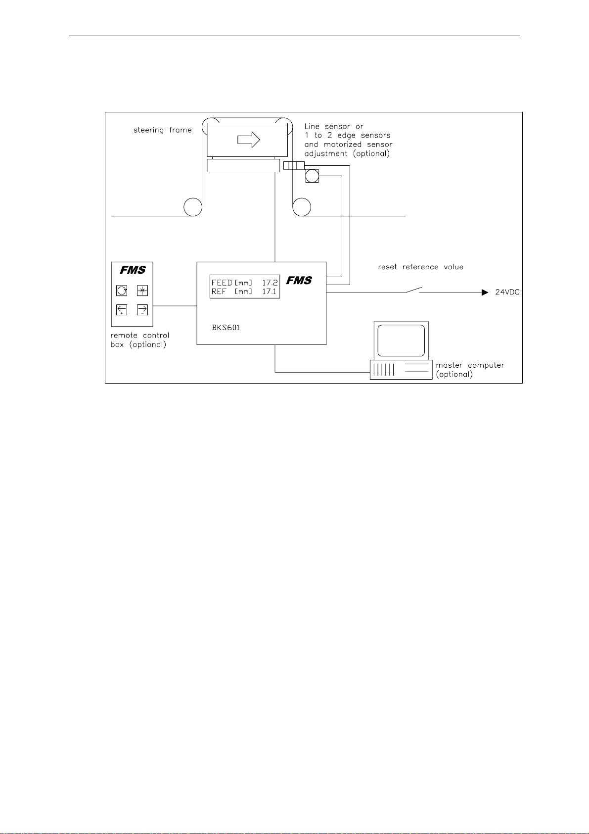
4System Description....................................................................................7
4.1 Functional Description 7
4.2 Steering Device 8
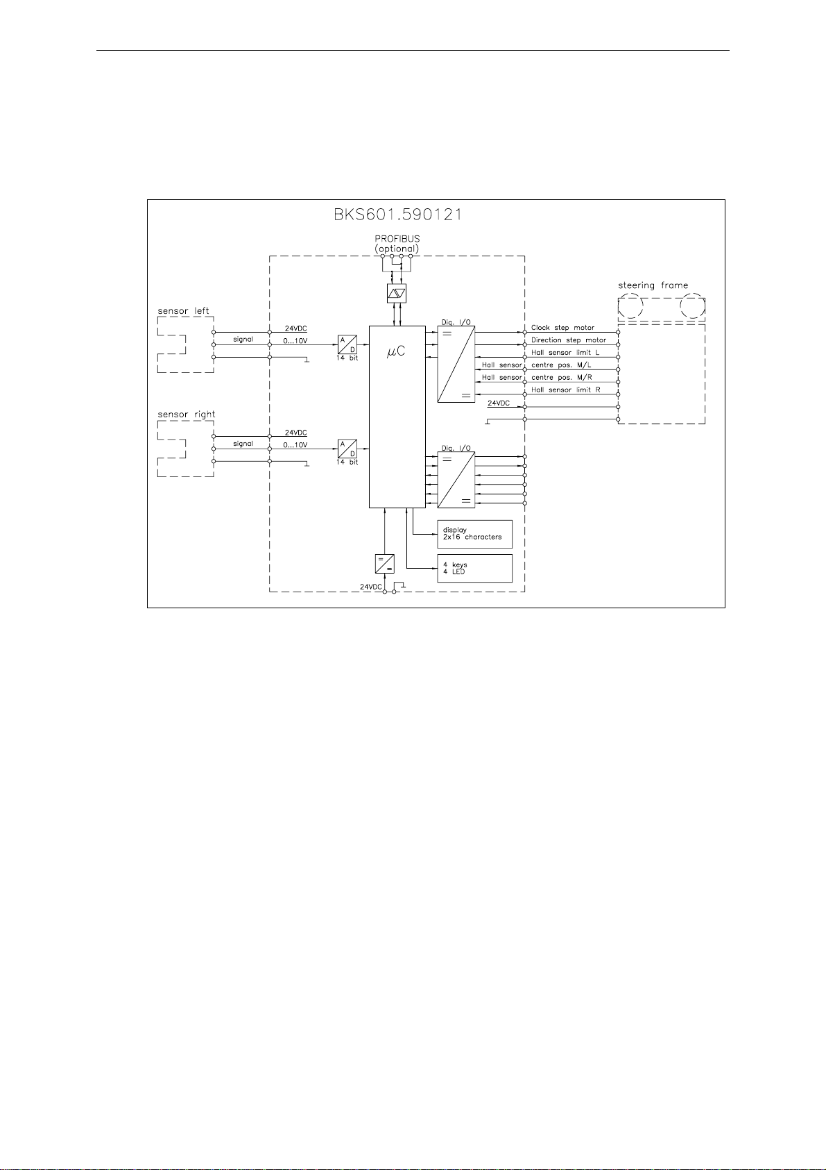
4.3 Electronic Control Unit 8
4.4 Sensors 9
4.5 Manual Sensor Adjustment 9
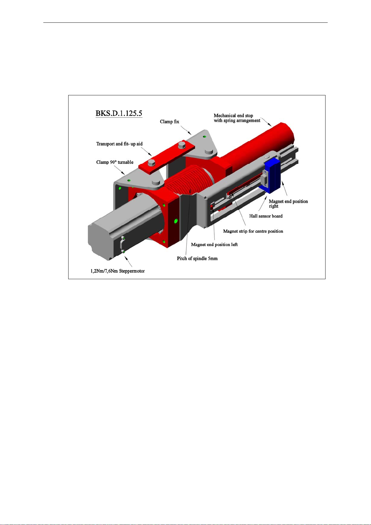
4.6 Linear Units 9
4.7 Remote Control Box 10
5Quick Installation Guide........................................................................10
6Dimensions...............................................................................................11
7Installation and Wiring ..........................................................................13
7.1 Mounting the Electronic Unit 13
7.2 Mounting BKS601C Wall Mounting Configuration 15
7.3 Wiring Diagrams 16
7.4 Mounting the Steering Device 19
7.5 Mounting of Manual Sensor Adjustment 19
7.6 Mounting of the Linear Units 20
7.7 Mounting of the Sensors 21
8Operation .................................................................................................22
8.1 View of the Operating Panel 22
8.2 Configuring the Electronic Unit 23
8.3 Main Operating Menu and Special Functions 24
8.4 Manual Operation 25
8.5 Operation without Linear Units 26
8.6 Operation with Linear Units 27
8.7 Measuring from a Reference Point on the Machine Frame 29
9ParametriSation ......................................................................................30
9.1 Flow Chart ParametriSation 30
9.2 List of the System Parameters 31
9.3 List of the Parameters BKS601C 31
9.4 Description of the System Parameters 32
9.5 Description of the Parameters BKS601C 33
9.6 Flow Chart Service Mode 37
9.7 List of the system service parameters BKS601C 38
9.8 List of the service parameters BKS601C 38
9.9 Description of System Service Parameters BKS601C 39
9.10 Description of the Service Parameters BKS601C 39
10 PROFIBUS Interface Description.........................................................43
10.1 Wiring the PROFIBUS Data Cable 43
10.2 Setting the PROFIBUS Address 44
10.3 GSD File 44
10.4 BKS601C.P DP Slave Functional Description 44

Operating Manual BKS601C
3
10.5 Initial Parameters 44
10.6 Configuration 45
10.7 Function Code 45
11 Serial Interface (RS232) .........................................................................46
12 Interface CAN-Bus..................................................................................46
13 Interface DeviceNet.................................................................................46
14 Technical Reference................................................................................47
14.1 Additional Setting Elements 47
14.2 Setting Elements on the Extension Board 48
14.3 Technical Data 49
15 Trouble Shooting.....................................................................................50

Operating Manual BKS601C
4
1Safety Instructions
1.1 Description Conditions
High danger of health
injury or loss of life Risk of damage
to machines Note for
proper function
Danger
This symbol refers to high
risk for persons to get health
injury or loss life. It has to be
followed strictly.
Caution
This symbol refers to risk
of heavy mechanical
damage. This warning has
to be followed absolutely.
Note
This symbol refers to an
important information
about proper use. If not
followed, malfunction can
be the result.
1.2 List of Safety Instructions
Proper function of the electronic unit is only guaranteed with the recommended
application of the components. In case of an other arrangement, heavy malfunction
can be the result. Therefore, the installation instructions on the following pages
must be followed strictly.
Local installation regulations are to preserve safety of electrical equipment. They are
not taken into consideration in this operation manual. However, they have to be
followed strictly.
Bad earth ground connection may cause electric shock to persons, malfunction of
the total system or damage of the electronic unit! It is vital to ensure that proper
ground connection is done.
The processor board is mounted to the housing cover. Improper handling may
damage the fragile electronic equipment! Don’t use rough tools such as
screwdrivers or pliers! Operators handling the processor board must wear a well
earthed bracelet in order to discharge static electricity.
If external parts are within the travel range of the linear units, the sensors can be
damaged while moving. Make sure that there is enough space between the linear
units and the external objects.
Wrong setting of the DIP-switches may cause malfunction of the electronic unit or
the total system. The DIP-switches are factory set and need no adjustment by the
customer.

Operating Manual BKS601C
5
2Definitions
Left and Right: Left and right are always seen in direction of the running web.
Linear unit: Motorized Sensor adjustment (optional variant). The sensor is
automatically adjusted by a linear guide to the edge or line that has to be detected.
Steering device: Steering frame, hydraulic cylinder with analog output or similar
actuator.
Dead band: Programmable tolerance band in which the web is allowed to move freely
without the control unit intervening. The web position is adjusted only when the
difference between reference and feedback position is greater than the dead band value
Sub-Board: Electronic module usually plugged to the main board of the electronic
unit. This modular approach allows to extended or change easily the features of the
electronic.

Operating Manual BKS601C
6
3System Components
The BKS601C web guiding system consists of the following components (see also Fig.
1):
Steering device
•Steering frame electrically driven with Plug & Drive stepper motor
Electronic unit BKS601C
•For all control functions
•With operation panel for menu controlled parametrisation
•Power amplifiers for the stepper motor drive and linear units
•RS232, PROFIBUS-interface, CAN-bus or DeviceNet
•Digital inputs and outputs
•Remote control box
•Robust aluminum housing
Sensors
•For detection of web edge or line
•1 or 2 analog sensors (also line sensor)
Linear units
•Linear units with Plug & Drive stepper motor and limit switch for reference
(Variants or options are indicated in italic text)

Operating Manual BKS601C
7
4System Description
Fig. 1: Basic structure of the BKS601C web guide K610034e
4.1 Functional Description
The sensors measure the position of the web and send this feedback signal as an
analog value to the electronic control unit. The control unit compares the position
feedback signal with the reference. If the difference is higher than a parametrized
value (dead band), the steering device is adjusted to bring the web into the right
position.
If the sensors are equipped with linear units, the controller automatically let them
follow the feedback position. The actual position of the sensors is taken into account
for the calculation of the web position.

Operating Manual BKS601C
8
4.2 Steering Device
The steering device adjusts the web position laterally. The correction is depending
from the web width.
Fig. 1a: FMS winderGLIDE BKS.D.1.125.5 K0411041e
As controlling and steering unit both FMS products webMASTER and winderGLIDE
can be used. The winderGLIDE BKS.D.1 is a dedicated devic for unwind- or rewind
stands.
4.3 Electronic Control Unit
General Remarks
The electronic unit is delivered in a robust aluminum housing. It contains the power
amplifiers for the actuator and the linear unit(s). The electronic unit goes with a
minimum of control elements. No trimming is necessary to guarantee its exceptional
long-time temperature stability and accuracy.
Operation
The large LCD display with 2x16 characters as well as the 4 LED’s and large keys
make its operation simple and efficient. All information is in plain text. Several
languages e.g. English, German, French and Italian are selectable. The most important
functions are programmable. Their parametrisation is done at the push of a few buttons
. All inputs are stored in none-volatile EEPROM memory. Additional settings can be
made with jumpers or solder bridges.

Operating Manual BKS601C
9
Interface
The user can optionally choose among several available interfaces (RS232, PROFIBUS, CAN-
Bus or DeviceNet). With the PROFIBUS interface, operation parameters and status values
can be read.
Fig. 2: Block diagram BKS601C K610035e
4.4 Sensors
Optical sensors (AZS01, AZS04A), ultrasonic sensors (US01B, US04B) and a digital
line sensor (DLS) are offered by FMS to work in conjunction with the BKS601C. No
special measures are required to operate these sensors with the electronic unit. The
alignment is done automatically.
4.5 Manual Sensor Adjustment
Manual sensor adjustment allows an easy positioning of the sensor across the whole
material width. Correct and stable focusing of the sensor is guarantied across operation
life.
4.6 Linear Units
Linear units (also called motorized traverses) allow a comfortable and precise
positioning of sensors. Control unit and sensors automatically scan the web for a
material edge or guiding line.
The kit can accept 1 or 2 linear units. The number of liner units, their travel range and
the assembly condition are specified by the customer. If required a fixed reference
point (e.g. edge of machine frame) can be defined where all position values will be
referred to.

Operating Manual BKS601C
10
4.7 Remote Control Box
The remote control box simplifies re-configuration the machine for a new job.
Specially in cases where the machine is difficult to access. Explanation of the keys:
Key
Use: Automatic On / Off. The automatic operation can be switched on or
off. The LED shines during automatic operation.
Key
Use: Center drive. The frame drives to the center position. (Not possible
during automatic operation).
Key
Use: During automatic operation, the reference value will be incremented
by steps of 0.1mm, if the key is pushed. If the key is kept pressed for
longer then 1 sec., the reference value will be increased
continuously.
Key
Use: During automatic operation, the reference value will be reduced by
steps of 0.1mm, if the key is pushed. If the key is kept pressed for
longer then 1 sec., the reference value will be decreased
continuously.
5Quick Installation Guide
•Check all your requirements such as:
– Control mode (edge left, edge right, center guiding, line).
– Number and position of the sensors?
– Steering device type (FMS steering frame or external actuator)?
– Configuration of digital inputs and outputs?
•Install and wire all your components (refer to „7. Installation and Wiring“)
•Turn power on and run the setup procedure according to „8. Operation“
•Proceed with a test run with low speed

Operating Manual BKS601C
11
6Dimensions
Fig. 3a: Dimensions of Electronic Unit for wall mounting BKS601C K600019e

Operating Manual BKS601C
12
Fig. 3b: Housing for panel mounting BKS601B.S.590121 K601021e
Housing variant Description
BKS601C standard housing for wall mounting (fig. 3a)
BKS601B.S.590121 housing for panel mounting (fig. 3b)

Operating Manual BKS601C
13
7Installation and Wiring
Caution
Proper function of the electronic unit is only guaranteed with the recommended
application of the components. In case of an other arrangement, heavy malfunction can
be the result. Therefore, the installation instructions on the following pages must be
followed strictly.
Caution
Local installation regulations are to preserve safety of electrical equipment. They are not
taken into consideration in this operation manual. However, they have to be followed
strictly.
Caution
Bad earth ground connection may cause electric shock to persons, malfunction of the total
system or damage of the electronic unit! It is vital to ensure that proper ground connection is
done.
7.1 Mounting the Electronic Unit
The housing can be mounted in a control cabinet or directly beside the machine. All
connections are led into the housing through glands and are connected to the plug-in
screw terminals according to the wiring diagrams (Fig. 7...12).
Fig. 4: Wiring inside the housing E600011e

Operating Manual BKS601C
14
Caution
The processor board is mounted to the housing cover. Improper handling may damage
the fragile electronic equipment! Don’t use rough tools such as screwdrivers or pliers!
Operators handling the processor board must wear a well earthed bracelet in order to
discharge static electricity.
Fig. 5: Screw terminal arrangement on the processor board E600003e
Fig. 6: Screw terminal arrangement on the extension board K610026e

Operating Manual BKS601C
15
7.2 Mounting BKS601C Wall Mounting Configuration
Fig. 6b: mounting BKS601C B600029d
Step by step assembly of the panel mounts housing:
1. Unscrew all 4 side screws (“Eckschrauben” see Fig. 6b)
2. Remove all cables connections of the electronic board on the front panel.
3. Detach the earth ground cable of the electronic board.
4. Remove the front panel from the box.
5. Now, the front panel can be mounted in the opening of the cabinet from the front
side.
6. In the back side of the cabinet bring together the front and back side of the box.
7. Put in place and screw the 4 fixation screws.
8. Re-establish the original cable connections. Don’t forget to connect the earth
ground cable.

Operating Manual BKS601C
16
7.3 Wiring Diagrams
Fig. 7: Wiring of the power supply and electronic unit K601012e
Fig. 8: Wiring of steering frame or other steering device K610029e

Operating Manual BKS601C
17
Fig. 9: Wiring of the edge sensors K610017e
Fig. 10: Wiring of the linear units K610018e

Operating Manual BKS601C
18
Fig. 11: Wiring of the digital inputs and outputs K610030e
Fig. 12: Wiring of the Profibus interface K610020e

Operating Manual BKS601C
19
7.4 Mounting the Steering Device
Assembly and wiring of the steering device is performed according to the
manufacturer’s specification. Bear in mind that the steering device is mounted such
that it takes into account the running direction of the web. If a steering frame is used,
the pivot point must be located at the edge of the inbound roller. Sensors must be
located at the exit side after the outbound rollers (Fig. 13).
Wiring is described in the wiring diagram (Fig. 8). The configuration of the screw
terminals in the electronic unit are seen in (Fig. 5)
Fig. 13: Definition of running direction in the steering device K600005e
7.5 Mounting of Manual Sensor Adjustment
With regard to the running direction of the web, the manual sensor adjustment is
installed after the steering device (Fig. 13). It has to be mounted on the static part of
the machine frame. The sensors are movable on the square bar and can be locked with
the retaining screw.
Note
In order to achieve an optimal controlling performance, the sensors must be placed
near to the outbound roller of the steering frame. If the sensors are placed far from the
steering frame, control dynamics will deteriorate drastically.

Operating Manual BKS601C
20
7.6 Mounting of the Linear Units
The linear units (Fig.1) must be installed after the steering frame referring to the
running direction (Fig. 13). They have to be mounted on the static part of the machine
frame using the provided brackets.
For the wiring of the linear units please consult the wiring diagram (Fig. 10). The
electronic control unit detects automatically if 1 or 2 linear units are connected.
Note
In order to achieve an optimal controlling performance, the linear units must be placed
near to the outbound roller of the steering frame. If the sensors are placed far from the
steering frame, control dynamics will deteriorate drastically.
Caution
If external parts are within the travel range of the linear units, the sensors can be
damaged while moving. Make sure that there is enough space between the linear units
and the external objects.
This manual suits for next models
1
Table of contents
Other FMS Industrial Equipment manuals
Popular Industrial Equipment manuals by other brands

Accelleron
Accelleron A100-H Series Assembly instructions

Shini
Shini SHD Product and maintenance manual

Metallkraft
Metallkraft KRBS 101 instruction manual

SCHUNK
SCHUNK PSH Assembly and operating manual

Kval
Kval 990FX Operation manual

Siemens
Siemens SIRIUS 3RA241-8X 3-1 Series Original operating instructions