Charles CP212-EP User manual
LT-CP212EP
1st Printing, March 30, 2017
©Copyright 2017 Charles Industries, Ltd. All Rights reserved. Printed in the United States of America.
Availability of features and technical specifications herein are subject to change without notice.
Charles is a registered trademark of Charles Industries.
Page 1 of 4
Expanded Base Installation Guide for Charles CP212-EP Pedlock®
Secondary Distribution Pedestal
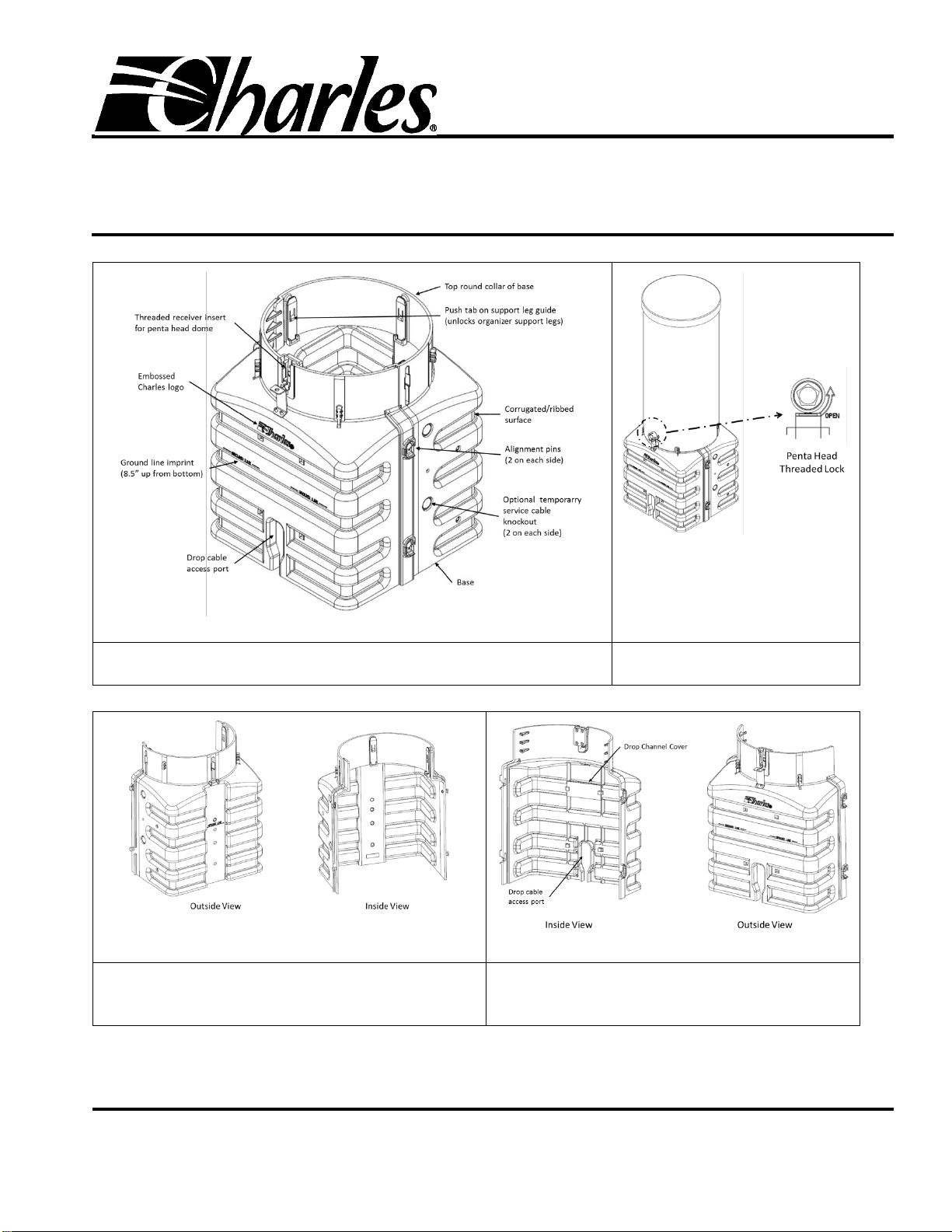
Figure 1 Expanded Split Base
Secondary Distribution Pedestal
Figure 2 Penta Head Lock
Secondary Distribution Pedestal
Figure 3 Rear Half
Expanded Split Square Base
Secondary Distribution Pedestal
Figure 4 Front Half
Expanded Split Square Base
Secondary Distribution Pedestal
LT-CP212EP
Page 2 of 4
1GENERAL INTRODUCTION
1.1 Document Purpose
This document provides general installation instructions for the CP212-EP series pedestals (and variants) designed for above-grade secondary
power distribution networks. Please follow company-specific installation practices.
1.2 Document Status
Whenever this document is updated, the reason will be stated in this paragraph.
Print 1 –First release of document.
1.3 Product Purpose
The Charles Pedlock® pedestal is an above-grade device that provides environmental protection for buried cables. Charles’ free-breathing
pedestal offers superior OSP protection against flood, fire, dirt, weather, salt-fog, insects, and impact. The pedestal’s expanded capacity, split
base can be opened to install around less flexible cables, inner-duct, or conduit-fed cable bundles in new construction, around existing cable or
conduit in pedestal replacement or rehabilitation applications. The square design and ribbed walls provide extra stability.
1.4 Product Mounting and Location
The pedestal base is installed (per local practice) in a trench or hole in the ground, up to the Ground Line (GL) indicator (see Figure 1). When
the base is installed, the pedestal is easily secured with the overlapping outer dome. The outer dome is secured to the base with an interlocking
dome tab and threaded penta-head lock, which can be secured to the pedestal base using the integrated hasp bracket along with a user-supplied
locking device.
-GROUNDING WARNINGS
Always follow local codes and company practices for performing proper cable and site bonding and grounding. Perform all bonding
and grounding prior to fiber, electrical, and communications connections.
-CABLE WARNINGS-
Be careful not to damage any buried cables or service wires while digging either to expose cables or to prepare a hole or trench, or
while driving stakes.
-BODILY HARM WARNINGS-
Cable components may be very sharp. Extreme caution should be taken to prevent personal injury. Protective work gloves are
recommended when handling electrical cable.
2INSTALLING THE PEDESTAL BASE
Follow the steps in Table 1 to install a Charles expanded pedestal base in a trench. Follow company practice regarding bonding/grounding
procedures.
Table 1 Installing an Expanded Pedestal Base
Step
Instruction
1
Prepare trench. Be careful not to damage any buried cables or wires while digging. Dig and prepare the cable trench, per local
company practices.
2
Establish an earth ground. Verify an earth ground is accessible and available at or near the pedestal base installation site.
3
Place cables, conduit, or inner-duct into trench. Place or lay cable/conduit in the trench per local practice. In the final position,
conduit height should be 1.5 inches below the bottom of the base collar, but no higher than the bottom of the collar.
Note: The most accurate cut can be made after the base has been set to its proper depth.
4
Unpack and inspect equipment. Unpack and inspect the pedestal. Remove the pedestal from the shrink wrap/skid and inspect for
damage. If the equipment has been damaged in transit, immediately report the extent of the damage to the distributor or carrier.
5
Obtain tools, materials and equipment. Assemble the following tools and equipment to perform the pedestal base installation.
Penta-head wrench
Level
Clean, dry, pea gravel (approved 3/8”-5/8” diameter only)
Tape measure
Hammer/mallet
Safety glasses
Work gloves
Cable grounding materials and equipment
Soil tamping tool(s)
LT-CP212EP
Page 3 of 4
Step
Instruction
6
Remove dome from base. Using a penta-head wrench, turn counter-clockwise until the spring-loaded penta bolt floats freely.
Grasp the dome and slightly twist the entire dome counter-clockwise to unlatch the dome's rear lock feature. Then lift the dome off
the pedestal.
7
Open the base (optional). With the dome removed, the two halves of the base can be separated by lifting up the front half of the
base (Charles Logo) out of its alignment pins and away from the rear half.
8
Remove knockouts (if required). Generally, the stake, if used, is attached at the rear of the base, which has the knockouts already
removed for use with the Charles Universal Mounting Stakes (UMSxx-STD). For different mounting positions, the knockouts may
need to be removed.
To remove any knockout, pierce the material around the recessed portion with a utility knife, working the blade into several locations
around the knockout. After the blade has been pushed through the material at these locations, remove the knockout. CAUTION: Do
not use a hammer or punch to remove.
9
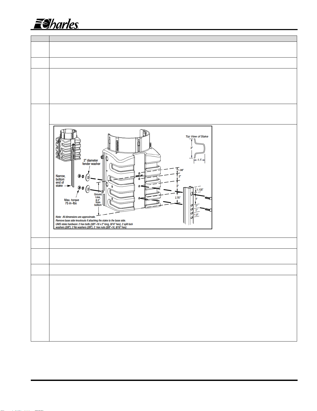
Install mounting stake. Install the mounting stake as shown in Figure 5. Attach the stake to the base by aligning the mounting bolts
to the desired knockouts. Next, press the stake to the outside of the base and insert the bolts into the base holes from the outside.
Place a 2” diameter washer and lock washer onto each bolt. Tighten bolt to a maximum of 75 in- lbs. Use only the supplied
galvanized hardware.
Figure 5 Mounting the UMS Stake on the Base
10
Assemble the base. If the cable tails can fit through the base collar, the two halves can be assembled prior to positioning the base.
Lift the front half over and onto the four alignment pins.
11
Determine base installation location. Position the base in the approximate desired position in the trench. The front or drop side of
the base (Charles logo) generally faces the street. Using either the back half of the base or the entire assembly, position the feed
cables/conduit toward the rear of the base.
12
Place/prepare earth ground. Always follow local codes and company practice when preparing earth ground and when grounding
cables/equipment. Per local company practice, prepare an earth ground for the pedestal at or near the base.
13
Position and level base in trench and begin backfill. Position the base and level per company practice.
Note: Maintain a level base as backfill is being added and tamped. Once the cables/conduit has been positioned, the base can be
placed in the trench with the optional attached stake (see Figure 5 and Step 9).
As the trench is backfilled, periodically tamp the soil, always pushing the soil toward the base. This practice will help remove air from
the backfill soil, making settling less likely to occur (see Figure 6). The base is designed to maintain its orientation after installation;
therefore, it is important to verify that the base is level during the entire installation procedure.
Note: Should it be necessary to straighten a pedestal at any future time (such as in the event of uneven ground settling),
never attempt to straighten an installed pedestal by manipulating, pushing, or pulling on the attached dome, as pedestal
damage may result. To re-plumb and straighten a pedestal after initial installation, first remove the soil from around the
base, then re-adjust the base until a proper level is achieved.
LT-CP212EP
Page 4 of 4
Step
Instruction
14
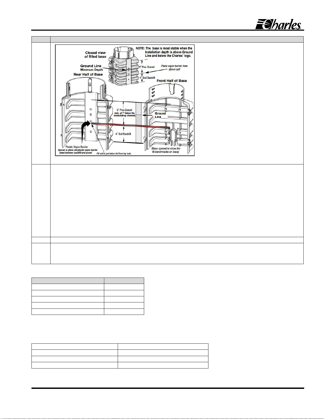
Figure 6 Backfill Levels Inside the Base
15
Install backfill soil, moisture barrier and pea gravel. Referring to Figure 6, alternately backfill the base, inside and outside,
tamping the soil as it is added. The soil on the inside of the base should cover the second rib from the bottom. On the outside, the
backfill should be even with or above the ’Ground Line’ but below the dome. Installing the base one rib higher than the ground line
makes the base more stable.
Caution: Never mound backfill soil on the outside of the base to make it appear that the base has been installed to the
recommended depth.
When the backfill on the inside of the base has been added to the proper height, the red moisture barrier is installed. The moisture
barrier sheet should be fitted around cables/conduits, slitting the sheet when necessary. Plug all open conduits prior to pouring in
any pea gravel (clean, dry, pea gravel, 3/8”-5/8” diameter only). Referring to Figure 6, pour 5 to 6 inches of pea gravel into the base.
The gravel should be no higher than the uppermost rib.
Note: If the conduit has been trimmed to the height described in Step 3, the gravel will be 1-1.5 inches below the top of the duct.
16
End of base installation - determine next procedure. Perform required wiring connections as required.
17
Install dome. Note: The dome can only be fully installed when there is no cable in the way. Lift the dome over any cables, aligning
the dome lock with the base receiver. Twist the dome clockwise to engage the dome to the base’s rear inter-locking tab. Using the
penta-head tool, push and turn the spring loaded lock bolt until tight (do not over-tighten). Attach secondary hasp lock between
dome locking cup and base hasp.
Table 2 Pedestal Base Physical Specifications
Feature
12” pedestal
Height, base only, incl. collar
18.5 in.
Height, base bottom to ground line
8.5 in.
Height, dome top to ground line
35 in.
Depth, base (front to back)
15.1 in.
Width, base (side to side)
16.1 in.
NOTE: All dimensions are approximate.
3CUSTOMER TECHNICAL SERVICE
If technical assistance or customer service is required, contact Charles Industries by calling or using one of the following options:
847-806-8500 (Tech. Service local)
847-806-6300 (Customer Service)
800-607-8500 (Tech. Service toll-free)
847-806-6653 (Customer Service FAX)
847-806-8556 (Tech. Service FAX)
mktserv@charlesindustries.com (email)
techserv@charlesindustries.com (email)
www.charlesindustries.com (website)
Table of contents
Other Charles Industrial Equipment manuals


