TLV UFO Series User manual
Copyright (C) 2007by TLV Co., Ltd. All rights reserved.
INSTRUCTION MANUAL
FREE BALL-BUCKET STEAM TRAP
UFO SERIES
UFO3-BN・UFO3F-BN
UFO3-CN

Introduction
Before beginning installation or maintenance, please read this manual to ensure correct use of the
product. Keep the manual in a safe place for future reference.
The UFO Series steam traps with thermostatic air vent strip are suitable for
applications up to 1.57 MpaG (230 psig) where there is a possibility of steam-locking,
or for batch operation process equipment, such as heat exchangers, heaters,
cylinder dryers and pressing machines. The traps discharge condensate
continuously and automatically, at a temperature slightly lower than saturation
temperature.
For products with special specifications or with options not included in this manual, contact TLV
for instructions.
The contents of this manual are subject to change without notice.
1 MPa = 10.197 kg/cm2, 1 bar = 0.1 MPa
―1―
DANGER WARNING CAUTION
CAUTION
1. Safety Considerations
• Read this section carefully before use and be sure to follow the instructions.
• Installation, inspection, maintenance, repairs, disassembly, adjustment and valve
opening/closing should be carried out only by trained maintenance personnel.
• The precautions listed in this manual are designed to ensure safety and prevent equipment
damage and personal injury. For situations that may occur as a result of erroneous handling,
three different types of cautionary items are used to indicate the degree of urgency and the
scale of potential damage and danger: DANGER, WARNING and CAUTION.
• The three types of cautionary items above are very important for safety; be sure to observe
all of them, as theyr elate to installation, use, maintenance, and repair. Furthermore, TLV
accepts no responsibility for any accidents or damage occurring as a result of failure to
observe these precautions.
Indicates an urgent situation
which poses a threat of
death or serious injury.
DO NOT use this product outside the recommended operating
pressure, temperature and other specification ranges. Improper use
may result in such hazards as damage to the product or malfunctions,
which may lead to serious accidents. Local regulations may restrict the
use of this product to below the conditions quoted.
DO NOT use this product in excess of the maximum pperating
pressure differential. Such use could make discharge impossible.
Take measures to prevent people from coming into direct contact
with product outlets. Failure to do so may result in burns or other injury
from the discharge of fluids.
Do not use excessive force when connecting threaded pipes to the
product. Overtightening may cause breakage leading to fluid discharge,
which may cause burns or other injury.
Use only under conditions in which no freeze-up will occur. Freezing
may damage the product, leading to fluid discharge, which may cause
burns or other injury.
Use under conditions in which no water hammer will occur. The
impact of water hammer may damage the product, leading to fluid
discharge, which may cause burns or other injury.
When disassembling or removing the product, wait until the internal
pressure equals atmospheric pressure and the surface of the
product has cooled to room temperature. Disassembling or removing
the product when it is hot or under pressure may lead to discharge of
fluids, causing burns, other injuries or damage.
DO NOT subject this product to condensate loads that exceed its
discharge capacity. Failure to observe this precaution may lead to
condensate accumulation upstream of the trap, resulting in reduced
equipment performance or damage to the equipment.
Be sure to use only the recommended components when repairing
the product, and NEVER attempt to modify the product in any way.
Failure to observe these precautions may result in damage to the product
or burns or other injury due to malfunction or the discharge of fluids.
Indicates that there is a
potential threat of death
or serious injury.
Indicates that there is a
possibility of injury or equip-
ment/product damage.
―2―
―3―
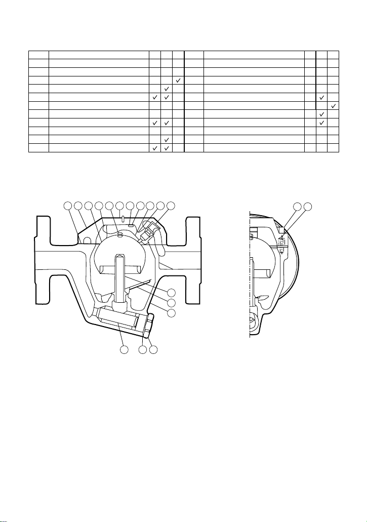
2. Configuration
No.
1
2
3
4
5
6
7
8
9
10
11
No.
12
13
14
15
16
17
18
19
20
21
Description Description
M* R* U* M* R* U*
Body
Cover
UFO Ball Bucket
Drain-jet
Drain-jet Gasket
Drain-jet Bushing
Blast-off Nozzle
Cover Gasket
Launching Pad
Screen
Screen Holder Gasket
Screen Holder
Cover Bolt
Nameplate
Guide Pin
Bimetal Strip
Pin
Spring Washer
Screw
Insulation Cover (Option)**
Binding Strip (Option)**
* M = Maintenance Kit, R = Repair Kit, U = UFO Kit ** See page 10 for details
Maintenance parts and repair parts are available only in kits, as shown above.
23456
7
9
1
18 1914 13 15
1716
10 11 12
8
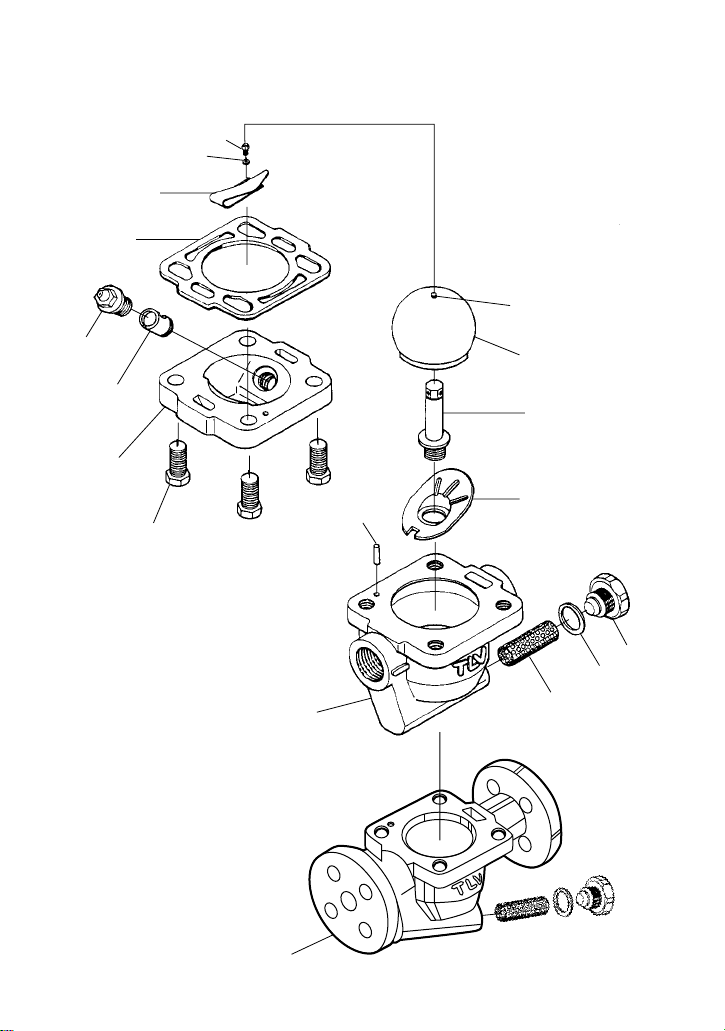
3. Exploded View
Screw
Spring Washer
Bimetal Strip
Cover Gasket
Drain-jet
& Gasket
Bushing
Cover
Cover Bolt
Body
(Flanged
Connection)
Body
(Screwed
Connection)
Screen
Screen
Holder
Gasket
Screen
Holder
Guide Pin
Launching Pad
Blast-off Nozzle
UFO Ball-bucket
Pin
―4―
Continued page 6
―5―
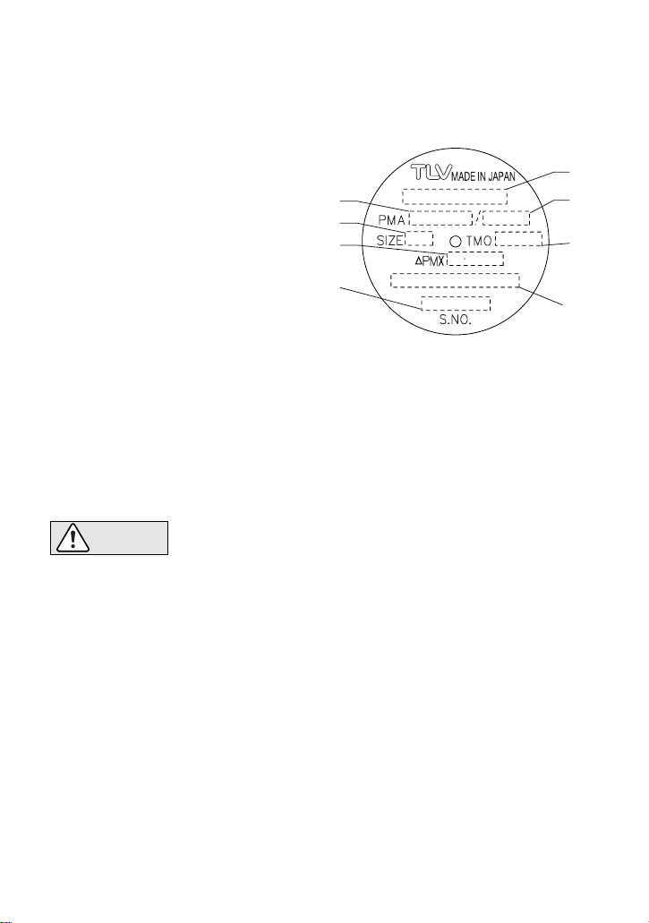
4 Specifications
5. Proper Installation
Refer to the product nameplate for detailed specifications.
A
Model
B
Nominal Diameter
C
Maximum Allowable Pressure*
D
Maximum Allowable Temperature*
E
Maximum Differential Pressure
F
Maximum Operating Temperature
G
Serial Number
H
Valve No.**
C
B
E
G
A
D
F
H
*
Maximum allowable pressure (PMA) and maximum allowable temperature (TMA) are
PRESSURE SHELL DESIGN CONDITIONS, NOT OPERATING CONDITIONS.
** "Valve No." is displayed for products with options. This item is omitted from the
nameplate when there are no options.
• Installation, inspection, maintenance, repairs, disassembly, adjustment
and valve opening/closing should be carried out only by trained
maintenance personnel.
• Take measures to prevent people from coming into direct contact with
product outlets.
• Install for use under conditions in which no freeze-up will occur.
• Install for use under conditions in which no water hammer will occur.
1. Before installation, be sure to remove all protective seals.
2. Install the steam trap within the allowable inclination, as shown overleaf. Also make sure that
the arrow mark on the body corresponds with the direction of flow.
3. Before installing the trap, blow out the inlet piping to remove all dirt and oil.
4. Install the trap in the lowest part of the pipeline or equipment so the condensate flows naturally
into the trap by gravity. The inlet pipe should be as short and have as few bends as possible.
5. Support the pipes properly within 800 mm (2.5 ft) on either side of the trap.
6. Install a bypass valve to discharge condensate, and inlet and outlet valves to isolate the trap in
the event of trap failure or when performing maintenance.
7. Install a check valve at the trap outlet whenever more than one trap is connected to the
condensate collection pipeline.
8. The use of unions is recommended to facilitate connection and disconnection of screwed
models.
CAUTION
―6―
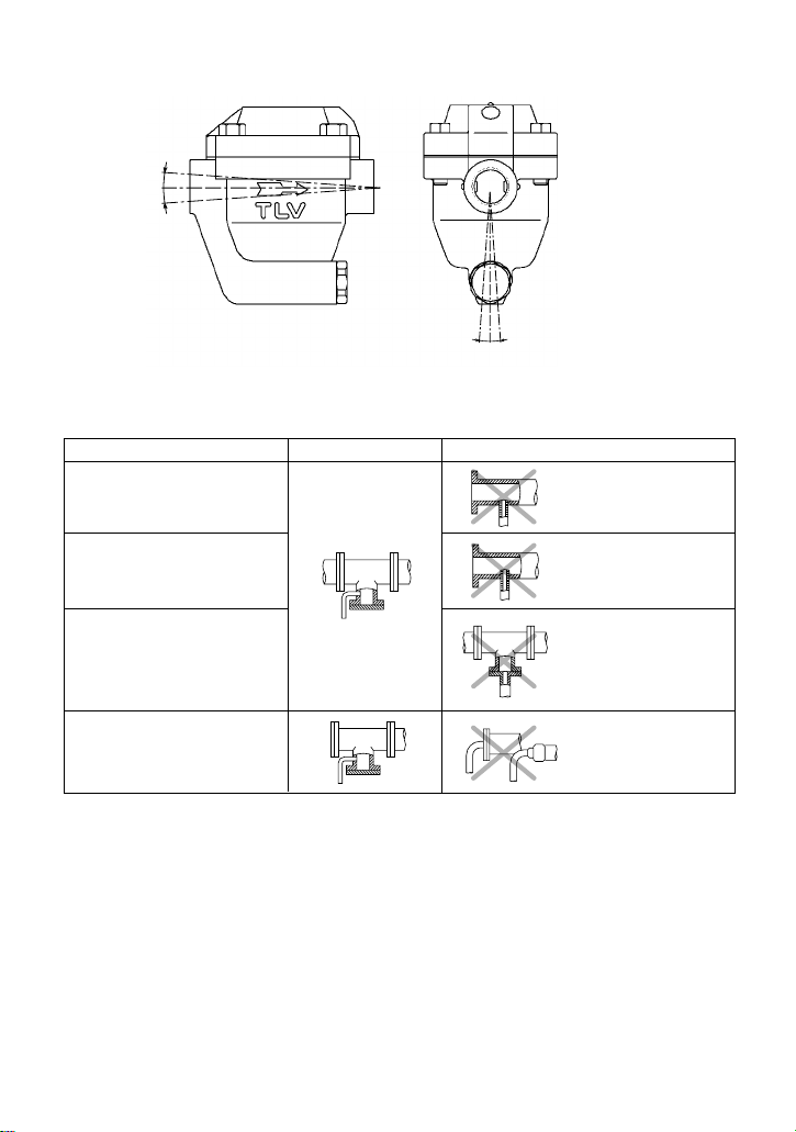
6. Piping Arrangement
Allowable Inclination
Requirement Correct Incorrect
Install a catchpot with the
proper diameter.
Diameter is too
small.
Diameter is too
small and inlet
protrudes into pipe.
Condensate
collects in the
pipe.
Make sure the flow of
condensate is not obstructed.
When installing on the
blind end, make sure
nothing obstructs the flow
of condensate.
To prevent rust and scale
from flowing into the trap,
connect the inlet pipe
25 - 50 mm (1 - 2 in) above
the base of the T - pipe.
Rust and scale
flow into the trap
with the
condensate.
Check to make sure that the pipes connected to the trap have been installed properly.
1. Is the pipe diameter suitable?
2. Has the trap been installed within the allowable inclination and with the arrow on the body
pointing in the direction of flow?
3. Has sufficient space been secured for maintenance?
4. Have maintenance valves been installed at inlet and outlet? If the outlet is subject to
back pressure, has a check valve been installed?
5. Is the inlet pipe as short as possible, with as few bends as possible, and installed so that the
condensate will flow naturally down into the trap?
6. Has the piping work been done with the proper methods as shown in the table above?
5°
5°
5°5°
7. Inspection and Maintenance
Operationalinspectionsshouldbeperformedatleasttwiceperyear,orascalledforbytrap
operatingconditions.Steamtrapfailuremayresultintemperaturedropintheequipment,poor
productqualityorlossesduetosteamleakage.
CAUTION • Inspection, disassembly, maintenance and repairs should be done only
by trained maintenance personnel.
• Before attempting to open the trap, close the inlet and outlet isolation
valves and wait until the trap has cooled completely. Failure to do so
may result in burns.
• Be sure to use the proper components and NEVER attempt to modify
the product.
Parts Inspection Procedure
Disassembly / Reassembly
Tightening Torque and Distance Across Flats
Body, Cover
Gaskets
Screen
Ball Bucket
Drain-jet, Blast-off Nozzle
Bimetal Strip
Check inside for dirt, grease, oil film, rust or scale
Check for warping or damage
Check for clogging, corrosion or damage
Check for deformation scratches and blockage of the vent hole
Check for clogging, corrosion or damage
Avoid touching or distorting the bimetal strip. Unscew it only if found
damaged
Part & No.
Part & No. UFO3-BN・UFO3F-BN
N・m (lbf・ft)
30
(22)
15
(11)
60
(43)
0.3
(0.2)
60 (44)
40 (29)
100 (73)
0.3 (0.2)
13 ( )
13 ( )
22 ( )
+
19 ( )
17 ( )
30 ( )
+
UFO3-CN
Cover Bolt 13
Cover 2
Cover Gasket 8
Bimetal Strip 16
Drain-jet 4
Drain-jet
Gasket 5
Screen
Holder 12
Screen Holder
Gasket 11
Screen 10
UFO Ball
Bucket 3
During Disassembly
Use a wrench to remove
Lift up the cover and clean the
sealing surface being careful not
to scratch its surface
Remove the gasket and clean the
sealing surface
Remove with a screw driver, being
careful not to bend the bimetal strip
Use a wrench to remove
Remove the gasket and clean the
sealing surface
Use a wrench to remove
Remove the gasket and clean the
sealing surface
Remove without bending
Use needle-nose pliers to grasp the
UFO by the pin on the top and lift
up to remove
During Reassembly
Coat threads with anti-seize, tighten to the
proper torque
Make sure there are no pieces of old
gasket left on the sealing surface and
reinstall the cover
Replace with a new gasket, do not
apply anti-seize
Consult the table of tightening torques
and tighten to the proper torque
Coat threads with anti-seize, tighten to
the proper torque
Replace with a new gasket if warped
or damaged
Coat threads with anti-seize and
tighten to the proper torque
Replace with a new gasket, coat
surfaces with anti-seize
Reinsert without bending
Insert being careful not to misshape
the UFO ball bucket
Cover Bolt 13
Drain-jet 4
Screen Holder 12
Screw for Bimetal Strip 19
N
・
m (lbf・ft)
mm (in) mm (in)
1 N
・
m 10 kg・cm
〜
〜
―7―
78
/
12
/
12
/
13 16
/
21 32
/
34
/
―8―
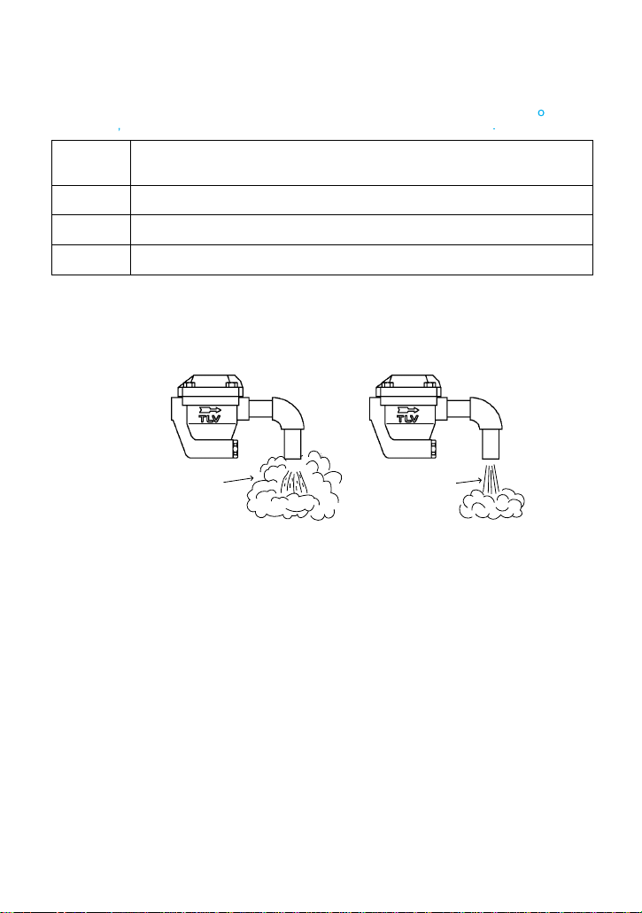
8. Operational Check
A visual inspection can be carried out to aid in determining the necessity for immediate
maintenance or repair, if the trap is open to atmosphere. If the trap does not discharge to
atmosphere, use diagnostic equipment such as TLV TrapMan or TLV PocketTrapman.
Normal:
Blocked:
Blowing:
Steam
Leakage:
Flash Steam Live Steam Leakage
Clear, slightly
bluish jet
White jet
containing
water droplets
Condensate is discharged intermittently with flash steam and the sound
of flow can be heard. If there is very little condensate, there is almost no
sound of flow.
No condensate is discharged. The trap is quiet and makes no noise,
and the surface temperature of the trap is low.
Live steam continually flows form the outlet and there is a continuous
metallic sound.
Live steam is discharged through the trap outlet together with the
condensate and there is a high-pitched sound.
(When conducting a visual inspection, flash steam is sometimes mistaken for steam leakage. For
this reason, the use of a steam trap diagnostic instrument such as TLV TrapMan is highly
recommended.)
―9―
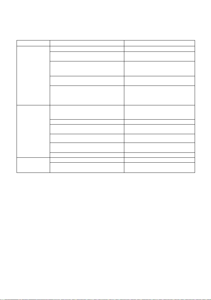
9. Troubleshooting
10. Product Warranty
If the expected performance is unachievable after installation of the steam trap, read chapters 5
and 6 again, and check the following points for the appropriate corrective measures.
Problem Cause Remedy
No condensate
is discharged
(blocked) or
discharge is
poor
Steam is
discharged or
leaks from the
trap outlet
(blowing)
(steam leakage)
Steam leaks from
a place other than
the trap outlet
The ball-bucket is stuck to the drain-jet
Drain-jet valve port, screen or piping
are clogged with rust or scale
Steam-locking has occurred
Flow exceeds trap's rated capacity
The trap operating pressure exceeds
the maximum specified pressure, or
there is insufficient pressure differential
between the trap inlet and outlet
Rust and scale has accumulated on
the drain-jet port or on the ball-bucket
surface
The drain-jacket is damaged
The ball-bucket is misshapen or
damaged
Trap is installed above the maximum
allowable inclination angle
Vibration of trap occurs
The bimetal strip is damaged
Deterioration of or damage to gaskets
Improper tightening torques were used
Clean
Clean
Blowdown through the bypass or
close the trap inlet valve and allow
the trap to cool
Check specifications and reselect
trap suitable for actual flow
Compare specifications and actual
operating conditions
Clean
Replace with new drain-jacket
Replace with a new ball-bucket
Correct the installation
Lengthen inlet piping, then fasten it
securely
Replace with a new bimetal strip
Replace with new gaskets
Tighten to the proper torque
NOTE: 1. Blowing may occur on bucket-type steam traps used at less than 10% of their maximum
discharge capacity. Therefore, do not use this trap for applications in which only small
quantities of condensate are produced.
2. When replacing parts with new, use the parts list for reference, and replace with parts
from the Maintenance Kit, Repair Kit or UFO Kit. Please note that replacement parts are
only available as part of a replacement parts kit.
1) Warranty Period: one year after product delivery.
2) TLV CO., LTD. warrants this product to the original purchaser to be free from defective
materials and workmanship. Under this warranty, the product will be repaired or replaced at
our option, without charge for parts or labor.
3) This product warranty will not apply to cosmetic defects, nor to any product whose exterior
has been damaged or defaced; nor does it apply in the following cases:
1. Malfunction due to improper installation, use, handling, etc., by other than TLV CO., LTD.
authorized service representatives.
2. Malfunctions due to dirt, scale, rust, etc.
3. Malfunctions due to improper disassembly and reassembly, or inadequate inspection and
maintenance by other than TLV CO., LTD. authorized service representatives.
4. Malfunction due to disasters or forces of nature.
5. Accidents or malfunctions due to any other cause beyond the control of TLV CO., LTD.
4) Under no circumstances will TLV CO., LTD. be liable for connsequential economic loss or
damage or consequential damage to property.
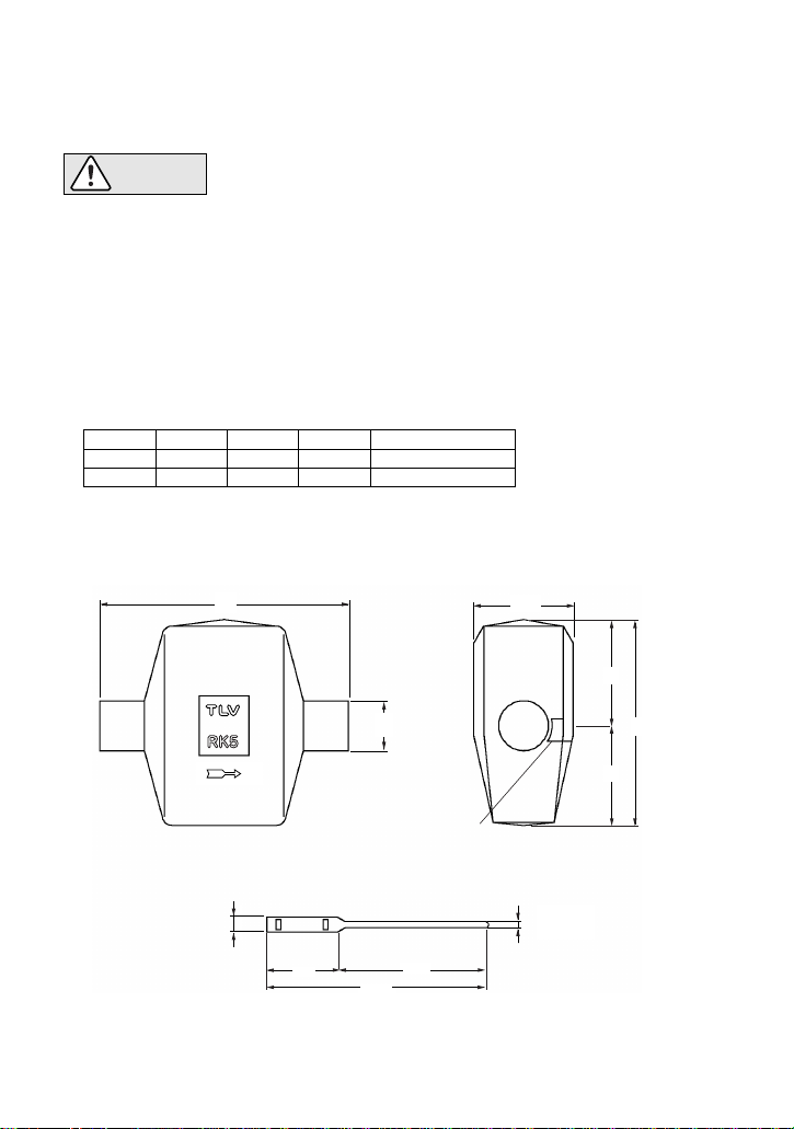
11. Optional insulation Cover RK3・RK5
One insulation cover set consists of a soft ceramic fiber case and two binding straps.
RK3 is for models UFO3-BN & UFO3F-BN, RK5 is for model UFO3-CN.
• Inspection, disassembly, maintenance and repairs should be done only
by trained maintenance personnel.
• Before installing the insulation cover, close the inlet and outlet isolation
valves and wait until the trap has cooled completely. Failure to do so
may result in burns.
CAUTION
Installation
1. Allow the trap to cool to ambient temperature.
2. Open the cover along the Velcro strip.
3. Place cover evenly around the body with the arrow on the cover
facing the same direction as the arrow on the trap body.
4. Reattach the Velcro strip.
5. Secure the ends of the cover around the trap inlet and outlet
with the binding straps.
Dimensions
RK3
RK5
A
205
250
B
40
50
C
80
100
D
70
100
E
150
200
Insulation Cover
Velcro Strip
Binding Strap
A100
220
70 150
D
φB
6
15
E
C
(mm)
―10―
881 Nagasuna, Noguchi, Kakogawa, Hyogo 675-8511, Japan
Tel: [81]-(0)79-422-1122 Fax: [81]-(0)79-422-0112
Manufacturer: Hersteller: Fabricant:
Rev. 7/2007 (M)
Printed on recycled paper.
For Service or Technical Assistance:
Contact your representative or your regional office.
66 Tannery Lane, #03-10B Sindo Building, Singapore 347805
Tel: [65]-6747 4600 Fax: [65]-6742 0345
ln East Asia:
881 Nagasuna, Noguchi, Kakogawa, Hyogo 675-8511, Japan
Tel: [81]-(0)79-427-1818 Fax: [81]-(0)79-425-1167
Or:
In Europe:
Daimler-Benz-Straße 16-18, 74915 Waibstadt, Germany
Tel: [49]-(0)7263-9150-0 Fax: [49]-(0)7263-9150-50
Parc d’activité Le Regain, bâtiment I, 69780 Toussieu (LYON), France
Tel: [33]-(0)4-72482222 Fax: [33]-(0)4-72482220
Star Lodge, Montpellier Drive, Cheltenham, Gloucestershire, GL50 1TY, U.K.
Tel: [44]-(0)1242-227223 Fax: [44]-(0)1242-223077
13901 South Lakes Drive, Charlotte, NC 28273-6790, U.S.A.
Tel: [1]-704-597-9070 Fax: [1]-704-583-1610
In North America:
Unit 22, 137-145 Rooks Road, Nunawading, Victoria 3131, Australia
Tel: [
61
]-(
0)3-9873 5610
Fax: [
61
]-(
0)3-9873 5010
ln Oceania:
Unit CT-8-12, Subang Square, Corporate Tower, Jalan SS15/4G,
47500 Subang Jaya, Selangor, Malaysia
Tel: [60]-3-5635-1988 Fax: [60]-3-5632-7988
Room 1201, No. 103 Cao Bao Road, Shanghai, China 200233
Tel: [86]-21-6482-8622 Fax: [86]-21-6482-8623
#1121 Trapalace, 10-1 Sunae-Dong, Bundang-Gu, Seongnam-Shi, Gyeonggi-Do, Korea
Tel: [82]-(0)31-726-2105 Fax: [82]-(0)31-726-2195
This manual suits for next models
3
Table of contents
Other TLV Industrial Equipment manuals


