Unit 17. Millbrook Business Park, Sybron Way • Crowborough, East Sussex TN6 3JZ United Kingdom
Phone: 00
44 (0)
1892-665313, Fax:
00 44
(0) 1892-668838
• E-mail:
[email protected], Internet:
Charleswater.co.ukPPE-5034.E November 2009 Page 1 of 2
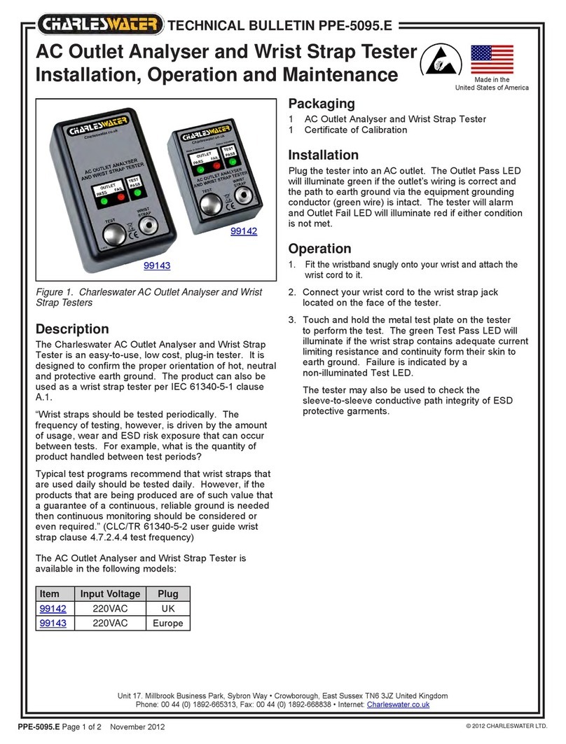
Figure 1. Charleswater 99090 Tester
Calibration Unit
Description
The Charleswater 99090 Tester
Calibration Unit is designed to
simplify the process of calibrating
the Charleswater 99000 and 99004
Combo Wrist Strap / Footwear
Tester. The calibration unit allows
the user to quickly and easily verify
whether the tester is operating within
specifications. The Calibration Unit
is a passive device, and requires no
power source. It is manufactured
with industry accepted test ranges
for both wrist straps and foot
grounders. The wrist strap pass
range is set at 825k- 35M, and the
foot ground test range is set at
825k - 35M. The Calibration Unit is
supplied calibrated to NIST traceable
standards.
Packaging
1 Tester Calibration Unit
2 Test Leads
1 Certificate of Calibration
Operation
WRIST STRAP TEST CIRCUIT
Step 1: Connect one of the test
leads to common point banana jack
“E” on the Calibration Unit. Connect
the opposite end of test lead to the
banana jack labeled “WRIST CORD”
located on the face of the Combo
Wrist Strap / Footwear Tester.
Ensure that the rocker switch on the
tester is set to WRIST CORD.
Step 2: Connect the second test
lead to the 675k jack labeled “A” on
Calibration Unit. Touch the opposite
end of test lead to tester’s test
plate and press down with enough
pressure to activate the test circuit.
Observe the LED’s for the proper
response as indicated below. Be
sure to hold the cord at an insulated
point, so that the resistance value is
not affected by the body.
Resistance Value Test Output - LED
Red jack “A” - 675k: Red (FAIL LO)
Green jack “B” - 825k: Green (PASS)
Green jack “C” - 35M: Green (PASS)
Yellow jack “D” - 40M: Red (FAIL HI)
Step 3: Repeat the procedure
testing across jacks B, C, and D on
the Calibration Unit. The different
resistance ranges should give
the display shown above. If the
tester does not meet calibration
specifications, contact Charleswater
for calibration.
Tester Calibration Unit
Operation and Maintenance
TECHNICAL BULLETIN
© 2009 CHARLESWATER LTD.
Ensure that the rocker switch on the
tester is set to FOOTPLATE.
Step 2: Connect the second test
lead to the 675k jack labeled “A” on
Calibration Unit. Touch the opposite
end of test lead to tester’s test
plate and press down with enough
pressure to activate the test circuit.
Observe the LED’s for the proper
response as indicated below. Be
sure to hold the cord at an insulated
point, so that the resistance value is
not affected by the body.
Resistance Value Test Output - LED
Red jack “A” - 675k: Red (FAIL LO)
Green jack “B” - 825k: Green (PASS)
Green jack “C” - 35M: Green (PASS)
Yellow jack “D” - 40M: Red (FAIL HI)
Step 3: Repeat the procedure
testing across jacks B, C, and D on
the Calibration Unit. The different
resistance ranges should give
the display shown above. If the
tester does not meet calibration
specifications, contact Charleswater
for calibration.
Made in America
Figure 2. Testing the Combo Tester’s
Wrist Strap Circuit
FOOTWEAR TEST CIRCUIT
Step 1: Connect one of the test
leads to common point banana jack
“E” on the Calibration Unit. Connect
the opposite end of test lead to the
banana jack labeled “FOOTPLATE”
located on the side of the Combo
Wrist Strap / Footwear Tester.
Figure 3. Testing the Combo Tester’s
Footwear Circuit


