CharlesWater 99000 Service manual
PPE-5011.E September 2013 Page 1 of 5
Tester, Combination, 3-State
Operation, Installation and Maintenance
Pass Range 750K - 35M
Figure 1. Charleswater 99000 Combo Tester
Description
The Charleswater Combo Tester is a 3-state touch tester
designed for fast, frequent testing of ESD personnel
grounding devices. The Combo Tester incorporates a
unique dual test circuit design which improves accuracy of
testing and eliminates the need for separate wrist strap and
foot grounder test units. The
99000
is equipped with a 750
Kilohm - 35 Megohm circuit, ideal for testing of wrist straps
and footwear.
Test parameters are factory set but can be adjusted to
match your own specifications. The Combo Tester is
very simple to operate. A green light signals the user that
everything is OK. A red light and an audible indicator means
that the circuit resistance is either too low or too high.
The testers each include a 80020, which
converts the banana plug on the face of the
unit into a 10mm snap. NOTE: Once the
80020 has been put into the plug socket, it
cannot be removed.
The tester operates on either a 9 volt battery or a special
AC adapter. The combo tester is available in two models:
the tester alone, or the tester with a stand. A footplate is
also available for use with the
99000
.
TECHNICAL BULLETIN PPE-5011.E
© 2013 Charleswater
Unit 17. Millbrook Business Park, Sybron Way • Crowborough, East Sussex TN6 3JZ United Kingdom
Phone: 00 44 (0) 1892-665313 • Internet: Charleswater.co.uk
Model Description
99000
Tester, Banana Jack
99004
Tester with stand
99013
Footplate, stainless steel
99065
AC Adapter, 220V
CAUTION: Use only the AC adapter designed for this
unit. Using any other adapters may damage the unit
and void the warranty.
Inspection
Remove the tester from the carton and inspect for damage.
Items included with model
99000
:
1 Combo Tester
1 9 volt battery
1 80020 converter
Items included only with model 99004:
1 Combo Tester
1 Base Plate
1 Pedestal tube with bracket and boot installed
1 10cm banan plug connector
1 Vinyl insulator cap
1 Wall poster
1 5/32" hex wrench
1 9 volt battery
1 80020 converter
Model number 99004 is ideally suited for testing foot
grounding devices. Item number 99013 can also be used in
conjunction with the combo tester for testing of footwear.
Installation of Model
99000
The Combo Tester may be used as a portable unit, or may
be permanently mounted on either a table or a wall. Please
refer to the following instructions when installing your tester.
Stationary Installation
If you will be using the tester as a portable unit, you may
prefer to mount the unit to a table or wall. Three keyhole
slots on the back of the unit are included to allow you to
attach the tester to a stationary surface.
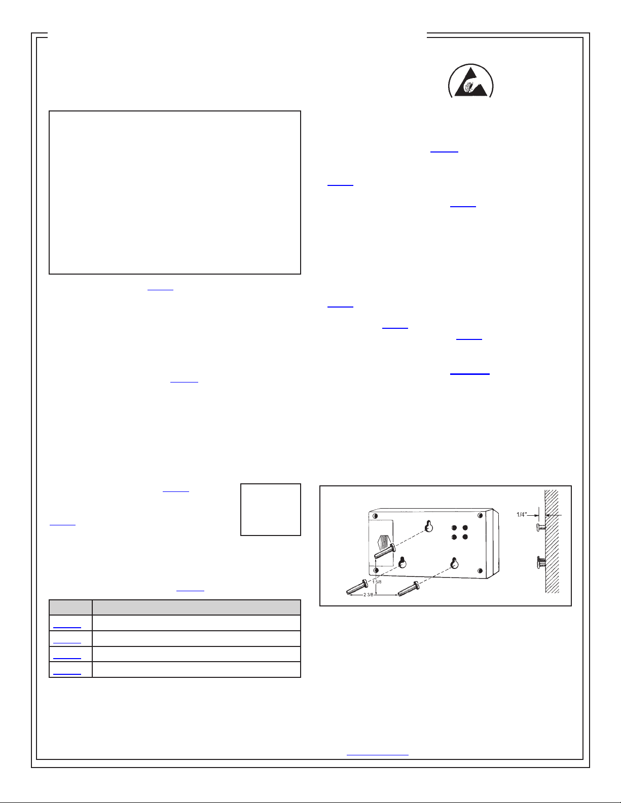
Figure 2. Mounting hole locations
1. Select location for mounting tester. Install three #6 or #8
screws spaced as illustrated in figure 3, into a wall or other
vertical surface. Make sure that the screw heads do not
project out more than 6.35 mm from mounting surface. The
template on page four is actual size.
2. Mount the tester on the screws, pulling down to lock it in
place.
Made in the
United States of America
PPE-5011.E Page 2 of 5 © 2013 Charleswater
Unit 17. Millbrook Business Park, Sybron Way • Crowborough, East Sussex TN6 3JZ United Kingdom
Phone: 00 44 (0) 1892-665313 • Internet: Charleswater.co.uk
Operation
The Combo Tester can be operated either on battery or
AC power. The unit comes equipped with a 9 volt alkaline
battery. For AC operation, plug the optional AC adapter into
the mini phone jack located on the upper left hand corner of
the tester. An AC adapter is sold separately as item number
99065 (220 volt).
LOW BATTERY INDICATOR
The Combo Tester includes a low battery indicator alarm
circuit. If both the audible alarm and indicator LED turn on
during use, discontinue testing and replace the battery.
The tester will continue to operate with a weak battery, but
results should not be considered accurate.
The battery can be easily replaced by removing the battery
compartment cover on the back of the unit and installing a
new 9 volt battery.
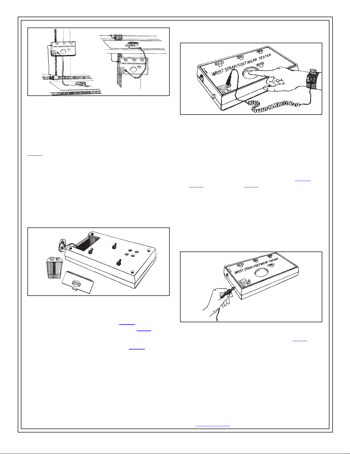
Figure 3. Stationary installation of the Combo Tester
Figure 4. Replacing the battery
General Instructions
In the following test configurations, the
99000
can be used
to test wrist straps while they are worn. Model 99004 will
also allow the user to test footwear.
WRIST STRAP TESTING WITH MODELS
99000
This test safely checks that a continuous path between the
operator, wrist strap and ground cord exists.
1. While wearing the wrist strap, plug the banana plug end
of the cord into the jack on the face of the unit.
2. Press rocker switch toward “WRIST CORD”.
3. Press the test button so that the unit activates. Hold
down for 2-3 seconds.
Note: DO NOT TOUCH ANY OTHER METAL WHILE
PERFORMING TEST.
Figure 5. Testing of wrist strap grounding assemblies
4. Lighting of the green “PASS” LED indicates that the wrist
strap and ground cord assemblies are functioning properly.
5. If either red “FAIL LO” or “FAIL HI” LEDs light and the
audible indicator sounds, the wrist strap wearer should
check the wrist strap assembly immediately.
TESTING FOOT GROUNDING DEVICES
In order to test footwear you will need the model
99000
with
the 99013 footplate, or the 99004. The following instructions
are intended for use while wearing foot grounding devices.
When testing conductive shoes, or foot grounders worn
on both feet, test each foot separately to ensure proper
operation and complete protection.
1. Place the Foot Plate on the floor in front of the Combo
Tester.
2. Plug the plate’s ground cord into the jack on the left hand
side of the unit.
Figure 6. Installing ground cord to “footplate” jack
NOTE: Steps A and B are not required with the 99004.
3. Place the rocker switch toward “FOOTPLATE”.
4. Place one foot on the plate. If the floor is conductive, lift
the foot you are not testing off of the floor during this test.
Make sure there is no cord plugged into the “WRISTCORD”
jack.
5. Press the test button so that the unit activates. Hold for
2-3 seconds.
PPE-5011.E Page 3 of 5 © 2013 Charleswater
Unit 17. Millbrook Business Park, Sybron Way • Crowborough, East Sussex TN6 3JZ United Kingdom
Phone: 00 44 (0) 1892-665313 • Internet: Charleswater.co.uk
6. Lighting of the green “PASS” LED indicates that the foot
ground assemblies are functioning properly.
7. If either red “Fail LO” or red “Fail HI” LEDs light and the
audible indicator sounds, the wearer should check the foot
grounding device immediately.
8. Repeat steps C through F with other foot.
Figure 7. Testing foot grounding devices with 99013
Free Standing Test Fixture Assembly
and Operation (Model 99004)
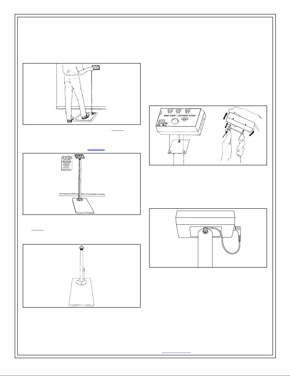
Figure 8. The Free Standing Test Fixture
The 99004’s rugged steel pedestal tube is powder coated
in a non-conductive white finish that helps to prevent false
readings if contacted by skin or loose smocks.
Figure 9. Attaching pedestal to baseplate
Assembly
1. Remove 3 screws from baseplate.
2. Position pedestal on the baseplate with the tester
mounting bracket pointing away from the operator. Attach
pedestal to baseplate using the three screws provided.
Tighten with hex wrench provided.
3. Open the battery compartment and attach the snap
connector to the included 9 volt battery. Attach poster to the
wall at eye level in front of the tester location.
4. Install the tester on the bracket by aligning keyholes on
the back of tester with mounting studs on bracket. While
pushing up on thumb screw, insert the mounting studs into
the keyholes and slide the tester down. See figure 10.
THUMB
SCREW
Figure 10. Installing tester on bracket
5. Install the 10cm banana plug connector to “FOOTPLATE”
jack on the side of the unit. Insert ring terminal behind
thumb screw.
6. Twist the thumb screw clockwise to secure the tester to
the bracket.
Figure 11. Secure tester to bracket
WRIST STRAP TESTING
This test verifies that a continuous path between the
operator, wrist strap, and ground cord exists.
1. While wearing the wrist strap, plug the banana plug end
of the cord into the jack on the face of the unit marked
“WRIST CORD”.
2. Press rocker switch toward “WRIST CORD”.
3. Press the test button so that the unit activates. Hold down
for 2-3 seconds.

PPE-5011.E Page 4 of 5 © 2013 Charleswater
Unit 17. Millbrook Business Park, Sybron Way • Crowborough, East Sussex TN6 3JZ United Kingdom
Phone: 00 44 (0) 1892-665313 • Internet: Charleswater.co.uk
NOTE: DO NOT TOUCH ANY OTHER METAL WHILE
PERFORMING TEST.
Figure 12. Testing of wrist strap grounding assemblies
4. Lighting of the green “PASS” LED indicates that the wrist
strap and ground cord assemblies are functioning properly.
5. If either red “FAIL LO” or “FAIL HI” LEDs light and the
audible indicator sounds, the wrist strap wearer should
check the wrist strap assembly immediately.
TESTING FOOT GROUNDING DEVICES
When testing conductive shoes or heel straps, test each
foot separately to ensure proper operation and complete
protection.
1. Press rocker switch toward “FOOTPLATE”.
2. Place one foot on the baseplate. If the floor is conductive,
lift the foot you are not testing off of the floor during this test.
Make sure there is no ground cord plugged into the “WRIST
CORD” jack.
3. Press the test button so that the unit activates. Hold down
for 2-3 seconds.
NOTE: DO NOT TOUCH ANY OTHER METAL WHILE
PERFORMING TEST.
Figure 13. Testing foot grounding devices
4. Lighting of the green “PASS” LED indicates that the foot
ground assemblies are functioning properly.
5. If either red “FAIL LO” or “FAIL HI” LEDs light and the
audible indicator sounds, the wearer should check the foot
grounding device immediately.
6. Repeat steps A through C with other foot.
Calibration
The models
99000
and 99004 are calibrated to factory
standards. We recommend that calibration is performed
annually to ensure that the Tester is operating within limits.
Due to its dual circuit design both test circuits of the Combo
Tester must be calibrated individually.
Charleswater offers a calibration unit that is specifically
designed to simplify the calibration procedure. This unit
comes calibrated to factory standards. For additional
information on the 99090, ask for Technical Bulletin
PPE-5034.E.
750 Kilohm - 35 Megohm TEST RANGE - WRIST
STRAPS
The following resistance should give the display shown:
Resistance Value Test Output
(±5% or better)
675 Kilohm Red (Fail Lo)
825 Kilohm Green (Pass)
35 Megohm Green (Pass)
40 Megohm Red (Fail Hi)
Figure 14. Calibration of the Combo Tester 750K to 35 M
range with the model 99090
750 Kilohm - 35 Megohm TEST RANGE - FOOTWEAR
The following resistance should give the display shown:
Resistance Value Test Output
(±5% or better)
675 Kilohm Red (Fail Lo)
825 Kilohm Green (Pass)
35 Megohm Green (Pass)
40 Megohm Red (Fail Hi)

PPE-5011.E Page 5 of 5 © 2013 Charleswater
Unit 17. Millbrook Business Park, Sybron Way • Crowborough, East Sussex TN6 3JZ United Kingdom
Phone: 00 44 (0) 1892-665313 • Internet: Charleswater.co.uk
Figure 15. Calibration of the Combo Tester 750K to 35M
range with the model 99090
To calibrate, simply test each resistance value shown
above which are included in the 99090 Calibration Unit.
Test across the test button and “WRIST CORD” jack for
calibration of the 750 Kilohm - 35 Megohm range. Test
across the test button and “FOOTPLATE” jack for calibration
of the 750K - 35M range. Be sure rocker switch is set
correctly.
Observe the LED’s for the proper response as indicated. Be
sure to hold the cord at an insulated point, so that resistance
value is not affected by the body. Should testing reveal that
the Tester is not functioning properly, verify that the battery
or power supply is operating correctly.
Tester calibration can also be verified with the use of
discrete resistors and two banana-to-alligator cords.
Adjustment
Detailed adjustment instructions are available from the
factory. Unauthorized modifications will void the product
warranty. Servicing should be performed only at the factory.
See warranty section for repair information.
Specifications
99000
and 99004 Wrist strap circuit
“Hi” Fail Factory set at 40M ohms
“Lo” Fail Factory set at 675K ohms
Footground circuit
“Hi” Fail Factory set at 40Mohms
“Lo” Fail Factory set at 675K ohms
General Characteristics
Power 9 volt battery or optional AC power supply
Operation Resistance bridge
Readout Three LED’s & audible alarm
Accuracy ±20%
Weight 227 grams
Height 14cm L x 4cm H x 8cm W
DRILL PATTERN
FOR
COMBO TESTER
ACTUAL SIZE
Limited Warranty
Charleswater expressly warrants that for a period of one (1)
year from the date of purchase, Charleswater Combination
Testers will be free of defects in material (parts) and
workmanship (labour). Within the warranty period, a unit will
be tested, repaired or replaced at Charleswater’s option, free
of charge. Call Customer Service at 00 44 (0) 1892-665313
for a Return Material Authorisation (RMA) and for proper
shipping instructions and address. Any unit under warranty
should be shipped prepaid to the Charleswater factory. You
should include a copy of your original packing slip, invoice,
or other proof of purchase date. Warranty repairs will take
approximately two weeks.
If your unit is out of warranty, Charleswater will quote repair
charges necessary to bring your unit to factory standards.
Call Customer Service at 00 44 (0) 1892-665313 for a Return
Material Authorisation (RMA) and proper shipping instructions
and address.
Warranty Exclusions
THE FOREGOING EXPRESS WARRANTY IS MADE IN LIEU
OF ALL OTHER PRODUCT WARRANTIES, EXPRESSED
AND IMPLIED, INCLUDING MERCHANTABILITY AND
FITNESS FOR A PARTICULAR PURPOSE WHICH ARE
SPECIFICALLY DISCLAIMED. The express warranty will not
apply to defects or damage due to accidents, neglect, misuse,
alterations, operator error, or failure to properly maintain, clean
or repair products.
Limit of Liability
In no event will Charleswater or any seller be responsible or
liable for any injury, loss or damage, direct or consequential,
arising out of the use of or the inability to use the product.
Before using, users shall determine the suitability of the product
for their intended use, and users assume all risk and liability
whatsoever in connection therewith.
Table of contents
Other CharlesWater Test Equipment manuals

CharlesWater
CharlesWater 99105 Installation guide

CharlesWater
CharlesWater 99090 Technical Document

CharlesWater
CharlesWater 99142 Installation and operating instructions

CharlesWater
CharlesWater Micro Meg Installation guide

CharlesWater
CharlesWater 99090 Installation guide

CharlesWater
CharlesWater 19770 Installation guide

CharlesWater
CharlesWater 99152 Installation guide

CharlesWater
CharlesWater 99036 Installation guide


