012-05293E Complete Rotational System
5
010 123456789
20 111213141516171819212224 10
987654321 20
191817161514131211 24232221
010
123456789
20
111213141516171819212224
10
987654321
20
191817161514131211 24232221
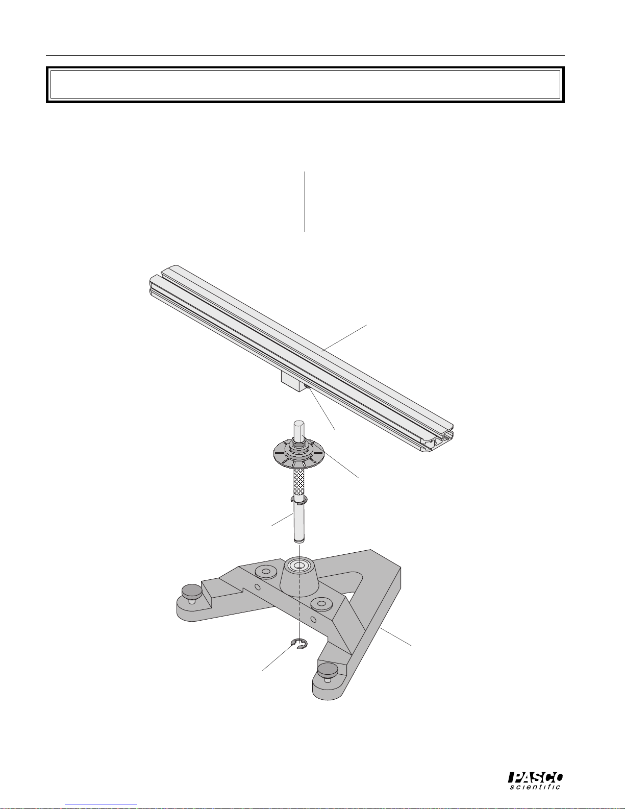
Figure 2: Leveling the Base
rotating platform
(rotated 90˚ as shown)
rotating
platform
in the pulley. If the photogate head is powered by a
computer, you can tell when the photogate is
blocked by watching the LED indicator on the end
of the photogate. The photogate head should not be
rubbing against the pulley. When the head is in the
correct position, tighten the bottom screw to fix the
rod in place.
"A" base
adjust this foot
first
leveling
feet
300g square
mass
300g square
mass
then adjust this
foot
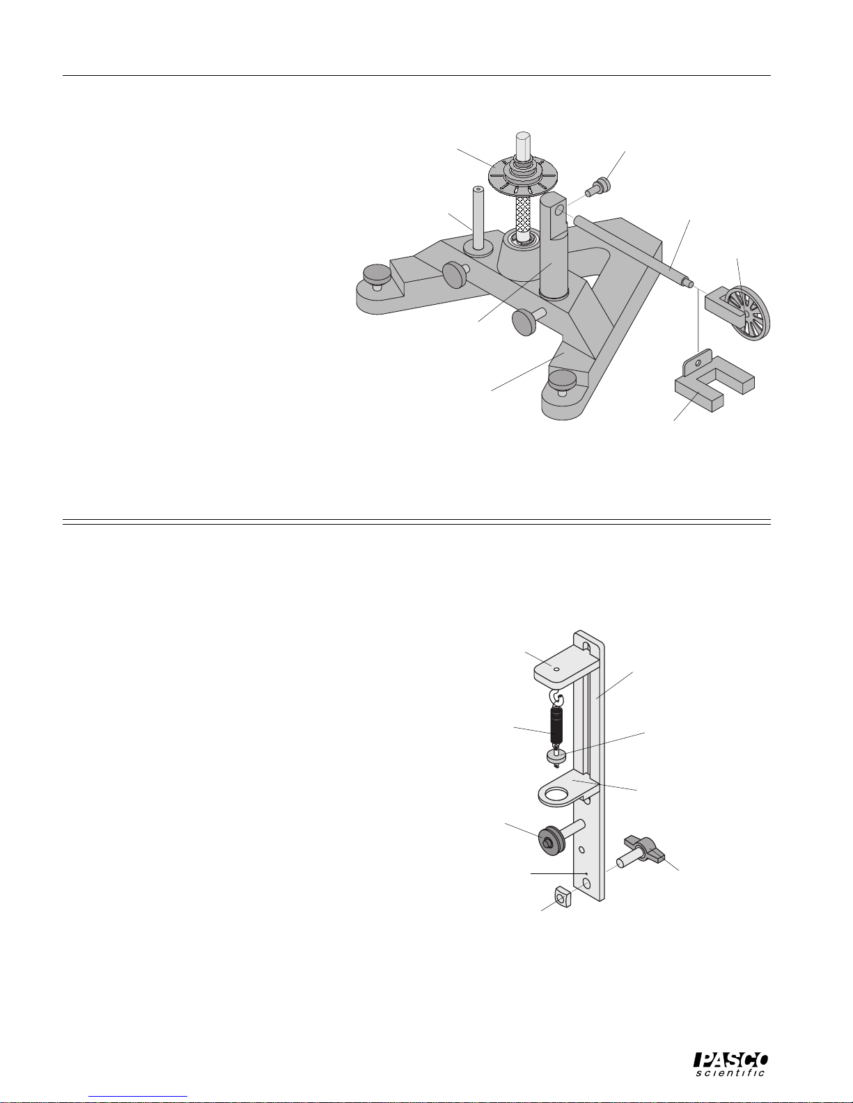
Installing the Optional Smart Pulley Photogate Head
The black plastic rod stand is designed to be used in
two ways:
• It can be used to mount a Smart Pulley photogate
head to the base in the correct position to use the
10 holes in the pulley on the rotating shaft to mea-
sure angular speed.
• It can be used to mount a Smart Pulley (with the pul-
ley and rod) to the base to run a string over the pulley.
To Use the Photogate Head Only:
➀To install, first mount the black rod to the base by
inserting the rod into either hole adjacent to the
center shaft on the base.
➁Mount the Smart Pulley photogate head horizon-
tally with the cord side down. Align the screw hole
in the photogate head with the screw hole in the flat
side of the black rod. Secure the photogate head
with the thumb screw. See Figure 3.
➂Loosen the thumb screw on the base to allow the
black rod to rotate. Orient the rod and photogate
head so the infrared beam passes through the holes
thumbscrew
"A" base
Smart Pulley
photogate head
(optional) nylon
thumbscrew
10-spoke
pulley on
vertical shaft accessory
mounting rod
Figure 3: Using the Accessory Mounting Rod With
the Smart Pulley
Leveling the Base
Some experiments (such as the Centripetal Force
experiments) require the apparatus to be extremely
level. If the track is not level, the uneven performance
will affect the results. To level the base, perform the
following steps:
➀Purposely make the apparatus unbalanced by at-
taching the 300 g square mass onto either end of the
aluminum track. Tighten the screw so the mass will
not slide. If the hooked mass is hanging from the
side post in the centripetal force accessory, place
the square mass on the same side.
➁Adjust the leveling screw on one of the legs of the
base until the end of the track with the square mass
is aligned over the leveling screw on the other leg
of the base. See Figure 2.
➂Rotate the track 90 degrees so it is parallel to one
side of the “A” and adjust the other leveling screw
until the track will stay in this position.
➃The track is now level and it should remain at rest
regardless of its orientation.
photogate
mount rod