Transmille 9000 Series User manual


Version 4.10 : May 2010
All product names are trademarks of their respective companies
9000 Series
Transportable Multi Product Calibrator
Operation Manual

9000 SERIES OPERATION MANUAL
TRANSMILLE LTD. Page 2
IMPORTANT NOTICE
THIS CALIBRATOR
WILL
REQUIRE AN
UNLOCK CODE
AFTER THE EVALUATION
PERIOD HAS EXPIRED.
(60 Days after invoice date)
AFTER THE EVALUATION PERIOD HAS EXPIRED THE OPERATION
OF THE CALIBRATOR IS LOCKED AND THE DISPLAY SHOWS A
NUMBER WHICH MUST BE QUOTED TO TRANSMILLE TO RECEIVE
THE UNLOCK CODE
THE UNLOCK CODE IS AVAILALBLE
FROM TRANSMILLE
ONLYAFTER PAYMENT
HAS BEEN RECEIVED.
This code is only needs to be entered once
in the life of the instrument.
Please contact Transmille or use the form in the
back of the manual to obtain the code.
Transmille Ltd.
Staplehurst , Kent.
Tel: 44 (0)1580 890700 : Fax 44(0)1580 890711

9000 SERIES OPERATION MANUAL
TRANSMILLE LTD. Page 3
DECLARATION OF CONFORMITY
Manufacturer’s Name: Transmille Ltd.
Manufacturer’s Address: Unit 4, Select Business Centre
Lodge Road
Staplehurst
TN12 0QW
Declares, that the product
Product Name: Multi-product Calibrator
Model Number: 9050 / 9041
Product Options: This declaration covers all options of the above product(s)
Conforms with the following European Directives:
The product herewith complies with the requirements of the Low Voltage
Directive 73/73EEC and the EMC Directive 89/336/EEC (including 93/68/EEC)
and carries the CE Marking accordingly
Conforms with the following product standards:
EMC
EN 61326-1:1997+A1:1998 • EN55011:1991 (Group 1 : Class A)
Standard Limit
IEC 61000-4-2:1995+A1:1998 / EN 61000-4-2:1995 4kV CD, 8kV AD
IEC 61000-4-3:1995 / EN 61000-4-3:1995 3 V/m, 80-1000 MHz
IEC 61000-4-4:1995 / EN 61000-4-4:1995 0.5kV signal lines, 1kV power lines
IEC 61000-4-5:1995 / EN 61000-4-5:1995 0.5kV line-line, 1kV line-ground
IEC 61000-4-6:1996 / EN 61000-4-6:1996 3V, 0.15-80 MHz / cycle, 100%
IEC 61000-4-11:1994 / EN 61000-4-11:1994 Dips: 30% 10ms; 60% 100ms
Interrupt > 95%@5000ms
SAFETY
IEC 61010-1:1990+A1:1992+A2:1995 / EN 61010-1:1993+A2:1995
18/07/2008
Revision No: 1.0 Managing Director
Date : 18/07/2008

9000 SERIES OPERATION MANUAL
TRANSMILLE LTD. Page 4
TABLE OF CONTENTS
9000 SERIES CALIBRATOR INTRODUCTION....................................................................................6
MAIN FEATURES..................................................................................................................................6
ACCURACY AND FUNCTIONALITY....................................................................................................7
TRUE MULTIPRODUCT CALIBRATION FROM ONE INSTRUMENT................................................7
PREPARING THE CALIBRATOR FOR USE........................................................................................9
INITIAL INSPECTION...............................................................................................................................9
TRANSPORTING THE CALIBRATOR .........................................................................................................9
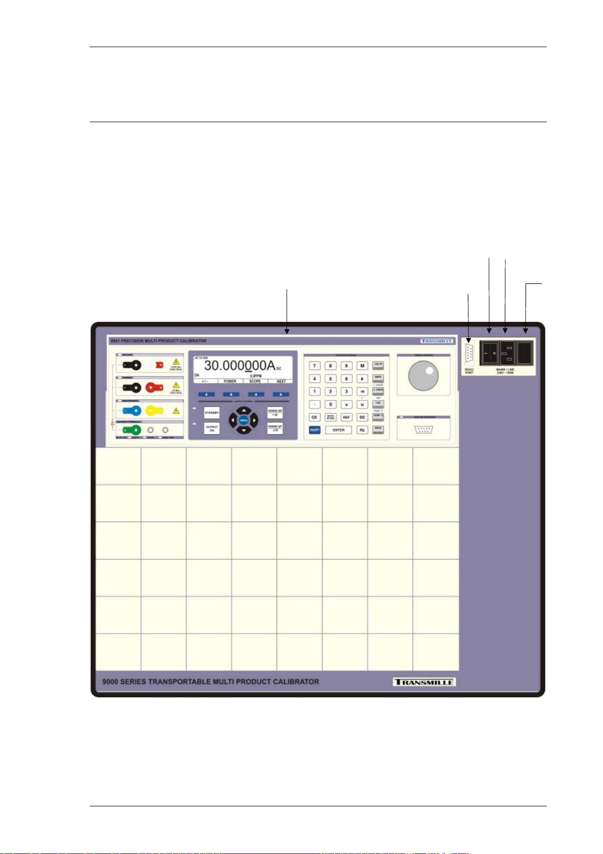
POWER / INTERFACE CONNECTIONS AND CONTROLS............................................................................10
SETTING AND CHECKING THE LINE VOLTAGE........................................................................................11
POWER LINE INLET FUSE AND RATING .................................................................................................11
CONNECTING TO A COMPUTER.............................................................................................................12
POWERING UP THE CALIBRATOR..........................................................................................................12
OUTPUT CONNECTIONS ......................................................................................................................13
OUTPUT OVERLOADS..........................................................................................................................14
OPERATION ........................................................................................................................................15
SAFETY WARNINGS ............................................................................................................................15
INTRODUCTION TO OPERATION............................................................................................................15
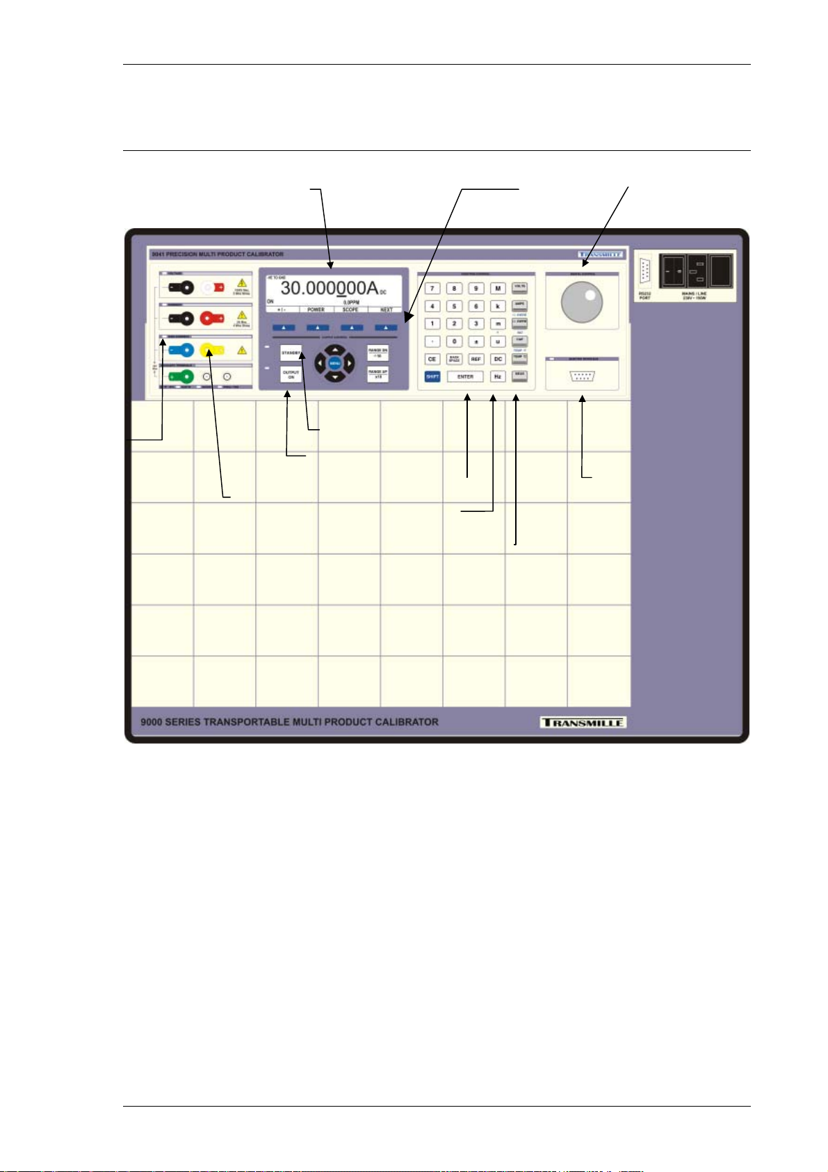
FRONT PANEL CONTROLS AND INDICATORS.........................................................................................16
FRONT PANEL KEYBOARD ..................................................................................................................17
FRONT PANEL KEYBOARD – CONTROL SECTIONS................................................................................18
GRAPHIC LCD DISPLAY .....................................................................................................................19
DIGITAL CONTROL..............................................................................................................................20
TERMINAL STATUS LED’S...................................................................................................................21
9 PIN ADAPTER INTERFACE CONNECTOR.............................................................................................23
SETTING A VOLTAGE OR CURRENT OUTPUT.........................................................................................24
ADJUSTING THE SET OUTPUT USING THE DIGITAL CONTROL...................................................................24
AUTOMATIC DISPLAY OF % OR PPM ERROR AND REF. KEY...................................................................25
SELECTING AC AND SETTING A FREQUENCY. ......................................................................................26
RETURNING THE CALIBRATOR TO DC...................................................................................................27
SETTING 2 WIRE RESISTANCE OUTPUT. ..............................................................................................28
SETTING 4 WIRE RESISTANCE OUTPUT. ..............................................................................................30
SETTING CAPACITANCE OUTPUT.........................................................................................................32
SETTING INDUCTANCE OUTPUT (OPTION) ............................................................................................33
THERMOCOUPLE SIMULATION (OPTION)...............................................................................................34
SPECIAL FUNCTIONS AVAILABLE USING THE ‘SOFT’ KEYS.....................................................................38
CONNECTING OUTPUT NEGATIVE TO LINE EARTH OR FLOATING.............................................................38
SELECTING FRONT PANEL CONTROL ....................................................................................................39
SETTING TTL LOGIC FREQUENCY OUTPUT..........................................................................................39
SETTING PWM (MARK SPACE RATIO).................................................................................................40
SELECTING PRT (PT100) RESISTANCE OUTPUT (OPTION)..................................................................41
SELECTING AC POWER CALIBRATION OUTPUT (OPTION).....................................................................42
SELECTING DC POWER CALIBRATION OUTPUT (OPTION).....................................................................44
SELECTING OSCILLOSCOPE CALIBRATION OUTPUT (OPTION)...............................................................45
WARNING AND OUTPUT OVERLOAD INDICATIONS...................................................................................47
HIGH VOLTAGE TIMEOUT. ...................................................................................................................47
30 AMP TEMPERATURE CUT-OUT........................................................................................................47
DRY BLOCK TEMPERATURE CALIBRATION MODULE .............................................................................48

9000 SERIES OPERATION MANUAL
TRANSMILLE LTD. Page 5
INTERFACE TYPES ............................................................................................................................49
RS232 INTERFACE.............................................................................................................................50
USB INTERFACE ................................................................................................................................52
REMOTE PROGRAMMING.................................................................................................................53
PROGRAMMING COMMANDS OVERVIEW...............................................................................................54
DC VOLTAGE COMMANDS ..................................................................................................................56
AC VOLTAGE COMMANDS ..................................................................................................................58
DC CURRENT COMMANDS..................................................................................................................60
AC CURRENT COMMANDS..................................................................................................................62
RESISTANCE COMMANDS....................................................................................................................64
CAPACITANCE COMMANDS..................................................................................................................66
SIMULATED RESISTANCE COMMANDS (OPTION)...................................................................................67
SIMULATED CAPACITANCE COMMANDS (OPTION).................................................................................68
TTL FREQUENCY COMMANDS (OPTION)..............................................................................................70
PULSE WIDTH MODULATION COMMANDS (OPTION)..............................................................................72
INDUCTANCE COMMANDS (OPTION).....................................................................................................74
PRT COMMANDS (OPTION).................................................................................................................76
THERMOCOUPLE SIMULATION COMMANDS (OPTION)............................................................................78
MISCELLANEOUS COMMANDS .............................................................................................................81
OSCILLOSCOPE CALIBRATION COMMANDS (OPTION) ...........................................................................82
POWER CALIBRATION COMMANDS (OPTION)........................................................................................91
TECHNICAL DESCRIPTION...............................................................................................................94
GENERAL...........................................................................................................................................94
CONSTRUCTION..................................................................................................................................95
INTERNAL FUSES................................................................................................................................96
OPENING THE ENCLOSURE .................................................................................................................97
ACCESS TO INTERNAL FUSES – FRONT PANEL PCB............................................................................97
POWER SUPPLY AND OUTPUT SWITCHING BOARD .................................................................................98
PROCESSOR BOARD...........................................................................................................................98
MAIN ANALOGUE AMPLIFIER AND FEEDBACK BOARD ............................................................................99
HIGH VOLTAGE AMPLIFIER AND OUTPUT............................................................................................100
CURRENT TRANSCONDUCTANCE AMPLIFIER ......................................................................................100
OUTPUT CURRENTS SENSING & SHUNTS...........................................................................................101
CALIBRATION TUTORIAL................................................................................................................102
GETTING THE BEST OUT OF THE CALIBRATOR.....................................................................................102
CALIBRATION AND MAINTENANCE..............................................................................................104
GENERAL.........................................................................................................................................104
ELECTRICAL SAFETY TESTS..............................................................................................................104
CLEANING OF THE FAN DUCT ............................................................................................................105
CLEANING THE EXTERNAL CASE ........................................................................................................105
CALIBRATION ...................................................................................................................................106
ADJUSTMENT OVERVIEW USING PC VIRTUAL FRONT PANEL SOFTWARE ...........................................107
ADJUSTMENT OVERVIEW USING CALIBRATOR FRONT PANEL CONTROLS...........................................109
GUARANTEE AND SERVICE ................................................................................................................110

9000 SERIES OPERATION MANUAL
TRANSMILLE LTD. Page 6
9000 Series Calibrator Introduction
The 9000 series of calibrators offer a
complete transportable multi product
calibration system in a rugged enclosure
providing AC/DC voltage & current,
resistance & capacitance as well as being
expandable with add on options.
The rugged enclosure incorporates built-in
castors and an integrated retractable
handle for easy transportation to
and from site.
Main Features
AC/DC Volts to 1025V
AC/DC Current to 30 Amps (20Amps for 9050)
AC/DC Current to 1000 Amps with 50 Turn Clamp coil Adapter
2 and 4 Wire Resistance to 1 GOhm (10 MOhm for 9050)
Capacitance • Inductance (Option)
PT100 resistance Simulation (Option)
Thermocouple Simulation (Option)
DDS Power / Harmonics (Internal Option)
250/350/600MHz Oscilloscope Calibration (Internal Option)
RS232 Serial Interface
Extendable Range Of Adaptors via the Adapter Interface

9000 SERIES OPERATION MANUAL
TRANSMILLE LTD. Page 7
Accuracy and Functionality
The 9000 Series calibrators are available in 2 accuracy grades including the
9041 (25ppm) and the 9050 (50ppm). The appearance of these units is the same
however the model is indicated on the model number label and shown on the display
at switch on.
True Multiproduct Calibration
From One Instrument
Designed to provide an accurate cost effective portable instrument for the calibration
of multimeters, clamp meters, frequency meters, temperature meters, capacitance
meters. Internal retro fit options allow the calibration of power meters, oscilloscopes
to 600MHz, inductance and LCR meters.
Designed for on use in the laboratory or portable on site calibration the 9000 series
calibrator is equally suitable for use in the standards laboratory or for on site
calibration work. The fast warm up time combined with the transportable, rugged
case with built-in castors makes the 9000 series calibrator the ideal on site solution.
The RS232 or USB interface allows direct connection to a portable PC.
Retro Fittable Options
Allows Extra Functions To Be Added As Required.
Several internal retro fit options including oscilloscope, power , inductance and PRT
allow the user to select the most cost effective solution for the calibration work
required at the time with the ability to add extra functions as required. External
options for the calibration of clamp meters, high accuracy thermocouple simulation
with auto CJC built into the TC connector, optical tachometers etc are also available
controlled via the front panel adapter interface

9000 SERIES OPERATION MANUAL
TRANSMILLE LTD. Page 8
Serial Line RS232 Interface
Available As Standard.
All functions and outputs of the series 9000 calibrator are fully programmable over
the RS232 interface fitted as standard. The use of the RS232 interface saves the
cost of fitting GPIB cards to the PC, and also allows easy connection to portable
PC’s, reducing the set up time for on site calibration.
Output Connection
The output terminal configuration is designed to match most DMM’s input
connection, e.g. volts/ohms, low current and high current eliminating the need for
lead changing during calibration. All outputs are isolated when not in use, an LED
indicator showing the active output pair.

9000 SERIES OPERATION MANUAL
TRANSMILLE LTD. Page 9
Preparing The Calibrator For Use.
Initial Inspection.
After shipment the calibrator should be inspected for any signs of external damage.
Should external damage be found contact the carrier immediately. Do not connect a
damaged instrument to the line power as this may result in internal damage. Please
keep the original box which can be used when returning the calibrator for service
and recalibration.
Transporting the Calibrator
The calibrator can be easily transported from one location to another by one person
using the built-in castors and retractable handle (ensure enclosure lid is closed and
securely fastened using the integral clips before moving). The calibrator should
always be placed down on a firm flat surface on its base feet - avoid excessive
shocks to the calibrator and always place down smoothly.
Warning : AVOID EXCESSIVE DROPS
May cause internal damage.

9000 SERIES OPERATION MANUAL
TRANSMILLE LTD. Page 10
Power / Interface Connections and Controls
Connections at the top right of the calibrator control panel are for line power via a 3
pin IEC connector incorporating the line fuse and on-off switch - Note the mains inlet
is filtered. A 9 pin Serial interface connector for the computer interface, this is
optically isolated from the calibrator output.
Mains / Line Inlet
(IEC) Connector
Fuse
Holder
Cooling Vents
(Keep Clear) RS232 Connector
(COM Port)
Power
Switch

9000 SERIES OPERATION MANUAL
TRANSMILLE LTD. Page 11
Setting and checking the Line Voltage.
Warning : The line power cord must have an earth
conductor to avoid risk of shock.
This instrument must be correctly earthed.
The calibrator has been designed to work from either 100-120 Volt line supply or
200 - 240 Volt line supply. Check supply voltage as marked on the panel before
connecting to line power. Connecting the calibrator to the wrong supply will cause
internal damage to the instrument. To change the line voltage it is necessary to
rotate the mains selection block next to the IEC line inlet for 110V or 230V
operation. The calibrator will have been shipped wired for 110V operation for USA or
230V for Europe.
Power Line Inlet Fuse and rating
The Power line inlet fuse is located directly above the power inlet. The correct fuse
rating is 3.15A Anti-surge for 230V operation and 5Amps Anti surge for 110V
operation
FUSE

9000 SERIES OPERATION MANUAL
TRANSMILLE LTD. Page 12
Connecting to a computer
If required, a standard serial 9 pin cable may be used to connect the calibrator to a
COM port on a PC. A Null modem cable is not needed.
RS232 Interface
Connection
Configuration BAUD RATE : 9600
PARITY : NONE
DATA BITS : 8
STOP BITS : 1
Cable Type Male to Female Serial Cable
Straight Though Pin Connection (Not Null MODEM)
Driver N/A
Powering up the calibrator
After connecting line power, the calibrator can be switched on with the line power
switch above the mains inlet socket on the rear panel.
The fan will start and the front panel display will illuminate indicating power. The
display will show a firmware version number and after a short delay, during which
time the processor performs a self test of the instrument, the display will show an
output of 0.0000mV DC.Allow the calibrator to warm up for 30 minutes to obtain
full accuracy, the fast start feature of the calibrator will give approx. 90% of full
specifications within 10 minutes. The calibrator has been designed to be powered up
continuously, automatically switching to a standby mode after a pre-set period of
time from the last command. In standby mode the display back light will turn off.
The control program can now be started on the computer, the program will establish
communication with the calibrator at which time the calibrator will download the
values of the internal standards.

9000 SERIES OPERATION MANUAL
TRANSMILLE LTD. Page 13
Output Connections
Warning : Risk of shock.
High voltages may be present on the output sockets.
Output sockets are all 4mm safety type, the voltage pairs contacts are low thermal
gold plated for minimum thermal EMF.
The 9000 series calibrators outputs have been designed to allow most multimeters
to be calibrated with minimal lead changing. There are 3 separate pairs of outputs :
1) Voltage, Resistance, Capacitance, frequency & Inductance
2) Current and 4 Wire Resistance
3) High 30A Current.
When an output terminal pair is not active they are completely open circuit and
isolated from the other outputs. As only one pair is active at a time on (except on 4
wire ohms) they may be combined together if required to match the meters input
arrangement.
One example configuration of a multimeter’s inputs is a single common low input
with voltage, current and high current input. To match this to the calibrator, simply
connect the 3 low outputs of the calibrator together and connect the voltage, current
& high current outputs to the appropriate meters input . Note that when outputting
ohms, the calibrator will use the voltage output terminals.

9000 SERIES OPERATION MANUAL
TRANSMILLE LTD. Page 14
A second example is where the meter has separate voltage and current inputs, often
using four wire ohms on both pairs. In this case simply connect the voltage and
current outputs to the meter’s inputs, the calibrator will use both the voltage and
current pair on four wire ohms.
It is recommended that the voltage and low current leads be high quality screened
cable with gold plated 4mm plugs fitted. The cable must be able to withstand 1025
volts AC and have an insulation resistance greater than 1Teraohm to avoid
introducing any shunting effect on the high resistance ranges.
Poor quality test leads will introduce noise, thermal emf and leakage errors on low
voltage & current ranges and also unstable readings on resistance and capacitance
outputs (see measurement techniques ). Special test leads are available from
Transmille, see accessories.
Warning : Under no circumstances should any voltage
be connected to the calibrator outputs
The low output can be connected to line earth or allowed to float as selected - see
operation section of this manual.. It is recommended that the low is earthed which
will help to reduce noise on high ohms and low current. If allowed to float with
respect to line earth the low must remain within 50 volts of line earth. Outputs are
optically isolated from the RS232 interface
Output Overloads
If the calibrator is unable to drive the load then the output will be turned off and the
calibrator returned to standby mode. The message STBY ! will be displayed on the
front panel. The output will be automatically reset on setting the output again.

9000 SERIES OPERATION MANUAL
TRANSMILLE LTD. Page 15
Operation
Safety Warnings
WARNING : The information in this section is intended only
for qualified personnel. The user must at all times be
adequately protected from electric shock. Qualified
personnel must ensure that operators of the equipment are
adequately insulated from connection points.
WARNING : This instrument is capable of generating both
DC and AC high voltages.
A soft carry-case and a hard transit case are available for
regular transportation of the calibrator.
Introduction to Operation
All functions of the 9000 Series Calibrator can be controlled from the front panel. or
controlled remotely by a computer over the interface. The front panel controls are
‘locked out’, but local control may be resumed by selecting a soft key - it must be
remembered that this action may disrupt the computer program.

9000 SERIES OPERATION MANUAL
TRANSMILLE LTD. Page 16
Front Panel Controls and Indicators
Active
Terminal
LEDs StandBy Button
LCD Display with
integral backlight
Safety Output
Terminals
Menu buttons
(Soft Keys)
Numeric Keypad
Multiplier Keys
Function Keys
Digital Control
Output On Button
Adapter
Interface

9000 SERIES OPERATION MANUAL
TRANSMILLE LTD. Page 17
Front Panel Keyboard
The front panel of the 9000 Series Calibrator utilises a high quality custom rubber
keyboard with tactile feel buttons and integral display window. The front panel can
easily be wiped clean with a soft cloth. Care should be taken not scratch the display
window.
IMPORTANT NOTE
The front panel key buttons are for use with fingers only - do not press
the key with hard or sharp objects e.g. Ball-point pens, pencils,
screwdrivers etc. Repeated actions like this will almost certainly cause
the keyboard to fail. (This will not be covered under warranty). Care
should also be taken when transporting the instrument, do not place
test leads on top of the panel which may get squashed into the display
area or keys which can also cause damage.

9000 SERIES OPERATION MANUAL
TRANSMILLE LTD. Page 18
Front Panel Keyboard – Control Sections
The Keyboard is divided into sections to allow easy operation.
Numeric section
Allows numeric values to be entered
Multiplier section
Mega (M), Kilo (K), milli (m), micro(u) or nano (n)
Function section
Volts (V), Amps(A), Ohms (2 & 4 Wire),
Farads(F), Celsius(C), & Frequency(Hz)
Range Up / Range Down
Allow the output to be multiplied / divided by 10.
Left / Right / Up / Down Arrow Keys
To select the digit to be controlled by the rotary control.
Output On / Standby keys
Allow the calibrators output to be disconnected from the
terminals. Led indicators are incorporated in these switches to
clearly show the output status.

9000 SERIES OPERATION MANUAL
TRANSMILLE LTD. Page 19
Graphic LCD Display
A back lit graphic LCD display shows the present output, instrument status, % or
ppm change from the entered value, and also the new value being entered. The
bottom line of the display is used to assign the function of the four ‘soft (menu)
keys’ immediately under the display. The display utilises a back light which
automatically turns off if no activity takes place. The back light turns on as soon as a
key is pressed or a command is received.
Output Value
Dynamic
Softkey Menu
Output ON / Standby
& -VE TO GND
Indicators
Deviation (PPM)
Function Specific
Configuration
Display
This manual suits for next models
2
Table of contents
Other Transmille Test Equipment manuals

Transmille
Transmille 1000 Series User manual

Transmille
Transmille 2100 Use and care manual

Transmille
Transmille 4610M User manual

Transmille
Transmille 3000A Series Use and care manual

Transmille
Transmille 4610M Owner's manual

Transmille
Transmille 3000 Series User manual

Transmille
Transmille 5080 User manual

Transmille
Transmille 3000 Series Use and care manual

Transmille
Transmille 2100 User manual

Transmille
Transmille 4610M Use and care manual