Charlie Lab Black Lite System MIXLITE User manual
8 In x 4 Out. Full Effects Digital Mixer
User Manual

Index
Introduction .............................................................3
Connections and controls ........................................4
Front Panel ..............................................................4
Channel Functions Mic1 / 2/3/4 ..............................5
Stereo Channel Functions 5/6 .................................6
Master Channel Functions ......................................7
Back anel ...............................................................8
Functions and Use ...................................................9
Advanced Functions ................................................9
Gra hic equalizer 28 bands .....................................10
Download (u grade) firmware Mixer and Ds .......12
A endix .................................................................13
Technical s ecifications ...........................................13

INTRODUCTION
First of all, CHARLIE LAB thanks you for urchasing the MixLite. Mixlite is a new digital converter
and mixer sized so small that it almost ocketable. Such miniaturization does not, however,
com romise quality and / or the available functions.
MixLite has:
• 4 mono XLR / Neutrik™ Jack balanced in uts
• 2 * ¼ "Stereo” in Jacks convertible to 4 mono Jacks
• 1 auxiliary stereo in ut, to connect, for exam le, another MixLite or another sound source, such
as the return of an external effect. Note that this assive auxiliary entrance, will be subject only
to adjustment of the Master volume for a total of 8 in uts, lus 1 assive stereo.
* Converting stereo channels to mono, tone controls, sent AUX-REV and SFX, will be
common.
Along with the above inputs on the rear panel are also present:
• 1, ¼ "mono unbalanced Monitor Out ut Jack (to connect, for exam le, a floor monitor)
• EXT. EFF., 1 mono ¼ "unbalanced Jack, out ut for an external effect, to be linked to a
ossible external effect (Send or Out of the external effect)
• the main out ut, Master Out ut 2 Jack ¼ " unbalanced, to connect to the audio system (final
ower, am lified monitors or other). The in ut / out ut sections are com letely
analog signals while signal rocessing is totally digital.
The advantages of such a configuration are:
• Elimination of the classic "GAIN" in ut, which in the most cases creates confusion for less
ex ert users. In fact, incorrect use of such controls can create distortions or strong background
noise.
• Certainty that the signals indicated by the VU Meters are valid throughout the ath of audio
signals. The Usage of the various settings is very intuitive, though allowing more
ex erienced users to "navigate" towards more so histicated functions.
Connections and commands:
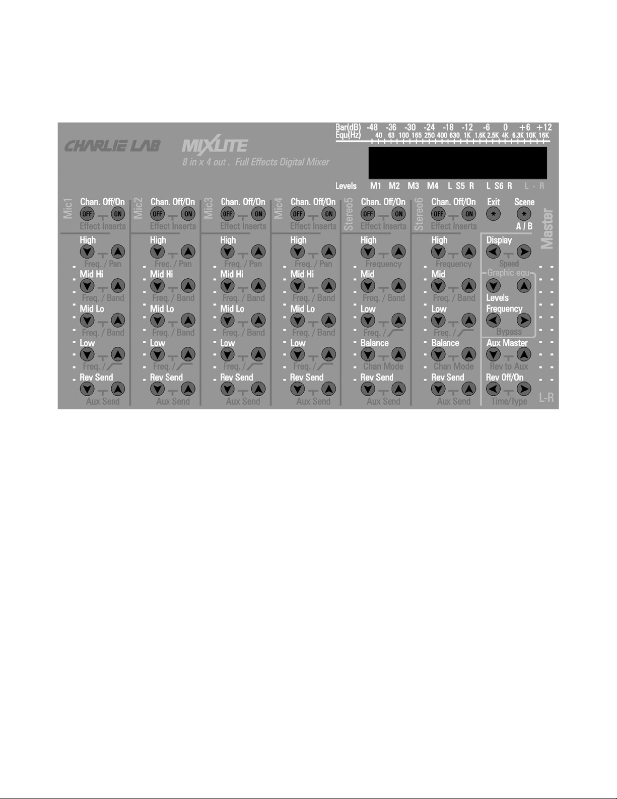
Front panel
The front anel has, from left to right, the adjustments of the first 4 mono channels (Mic 1/2/3/4),
followed by 2 Stereo Channels (Stereo 5/6).
Last to the right, the so-called "Master" section, which controls the final out ut.
At the bottom of the front anel are found head hone out ut, and a selector that lets you select
if the head hone out ut is L + R Stereo (such as general audio out uts), or as the auxiliary out ut
(monitor)

Functions available for Mono Mic / Line1-2-3-4 channels:
On / Off Channel-Com ressor-Noise
Gate-Pitch Detune
Decrease / Increase high frequencies,
relative frequency selection
intervention and Pan ot Adjustment
Decrease / Increase frequencies
medium high, relative selection
frequency of intervention and adjustment
bandwidth
Decrease / Increase frequencies
medium low, relative selection
frequency of intervention and adjustment
bandwidth
Channel volume slider adjustment
Decrease / Increase low frequencies,
Relative frequency selection
and On / Off Low Filter (100Hz)
Decrease / increase the amount of reverb
and auxiliary out ut level adjustment
(Aux)

Functions Available for Stereo Channels 5/6:
The functions of the 2 Stereo 5/6 channels differ from those of Mic 1/2/3/4
described above, regarding the 3-band equalizer, and the resence of the
controls related to balance.
On / Off Channel-Com ressor-Noise Gate
Decrease / Increase high frequencies and
Relative frequency selection
Decrease / Increase midrange frequencies,
Relative frequency selection
and bandwidth adjustment
Channel volume slider adjustment
Decrease / Increase low frequencies,
Relative frequency selection
and On / Off Low Filter (100Hz)
Pan ot Adjustment and Stereo / Mono
Selection
Decrease / increase the amount of reverb
and auxiliary out ut level adjustment
(Aux)

Functions Available for Master Channel:
Scene button call
Immediate Return Level Button
Show dis lay ty e, dis lay
s eed res onse adjustment
indicators and return timing
to automatic level of dis lay
Master volume adjustment slider
Gra hic Equalizer 28 bands
Boost / Cut of the selected frequency and
EQ reset ( ressing the two buttons for 3
seconds at the same time)
Selection of intervention frequency and
function
By ass (disables equalizer)
Auxiliary out ut level adjustment
(Aux) and Increment Adjustment Quantity
reverberation in Aux
Enable / Disable Reverb (Global),
decay time adjustment
reverb and reverb ty e selection

Back panel
(through which it is possible to access the various connections)
General audio out ut, to be connected to the am lified audio / monitor system or other ¼ "
Stereo Jacks
External effect out / Monitor Out
Stereo In uts 5&6
Mono Mic / Line In uts
Aux Ex ansion Bus In
Power Connector

Functions and use:
To use mixlite in the traditional way:
1) Move the MASTER slider to its ty ical osition (about 3/4)
2) Move the individual channel sliders until you get the desired sound level.
3) Verify that the levels shown on the leds matrix dis lay it is neither too high nor too low.
4) Acting on the "▲ ","▼ "of the res ective channel, modify the tones and / or adjust the level of the
reverb which can be edited using the Eff buttons.
Note: Pressing two adjacent buttons simultaneously for more than three seconds, the arameter
dis layed will be reset to the "default" value. It is ossible to recall all the MixLite's original
arameters (factory settings), by ressing Chan.Off/On of the stereo channel 6 while the equi ment is
owered on.
Advanced features:
At this oint if the user desires the functions that are normally only resent in rofessional ty e mixers,
you can access them sim ly by simultaneously ressing the 2 adjacent, relative buttons to the selected
function. At each ress, the dis lay will illuminate showing the new function; it will remain active for
some seconds so that they can be edited using the same individually ressed buttons (▲ & ▼). To go
back to the normal dis lay, just ress the EXIT key.
The automatic return to normal dis lay is definable in the "ESC" function by ressing the keys
Dis lay twice.
To better understand the conce t, here is the list of functions and subfunctions available on each of the
4 channels:
Mic (Mic 1-Mic4).
1) Chan. Off / On -> Com ressor Off / Ty e -> Noise Gate Off / Threshold -> Pitch Detune Off / Ty e
2) EQU High LEVEL -> FREQUENCY
3) EQU Midrange Hi LEVEL -> FREQUENCY -> BANDWIDTH
4) EQU Midrange Lo LEVEL -> FREQUENCY -> BANDWIDTH
5) EQU low LEVEL -> FREQUENCY -> Low Cut
6) Rev Send LEVEL -> AUX Send LEVEL
Below is a list of available functions and subfunctions
on each of the 2 Stereo Line (Stereo5-Stereo6) channels,
very similar to those of MIC 1/2/3/4
1) Chan. Off/On (*) --> Com ressor Off/Ty e (**) --> Noise Gate Off /Threshold (**)
2) Eq High LEVEL --> FREQUENCY
3) Eq Mid LEVEL --> FREQUENCY --> BANDWIDTH
4) Eq Low LEVEL --> FREQUENCY --> Low Cut (100Hz)
5) Stereo Balance --> Chan Mode Stereo/Mono
6) Rev Send Level --> AUX Send LEVEL

NOTE (**)
If the "Pitch Detune" effect is activated on the channel Mic1 and / or Mic2, the "Effect Insert"
of the "Stereo5" channel are not available. Similarly if the "Pitch Detune" effect is activated on the
Mic3 and / or Mic4 channel, the "Effect Insert" of the channel "Stereo6" are unavailable.
NOTE:
If Stereo 5 and / or Stereo 6 channels are in Off (Chan off), its Chan Mode is off.
Functions and subfunctions available on the channel Master Stereo:
Exit: Returns immediately to Level View (VU Meters)
Scenes: Pressing this key three times invokes Alternative memory arameters. Each arameter
is automatically saved in memory active. For exam le, if the active memory is "A", "A"
with "B", which becomes active. If at this oint modifying the arameters, these will
automatically be saved in the memory "B". "A" memory will remain unchanged from
exchange time. By ressing the button, three more times, I still call the "A" memory that
will return arameters of the condition before the exchange.
Dis lay: INPUTS -> OUTPUT -> GRAPHIC EQUALIZER
by selecting the "◄ ► "You can choose between:
INPUTS: The dis lay shows the levels of all channels and master stereo.
NOTE:
In this dis lay, the any channels that exceed the maximum allowed level. Because in this
case, distortions may occur of the audio signal, intervene by lowering its level.
OUTPUT: The dis lay shows the Master stereo level in high recision.
GRAPHIC EQUALIZER: The dis lay is a gra hic analyzer to 28 bands.
By ressing the "◄ ► ", is' You can adjust the arameter S eed , which determines the
res onse bars of LED bars in the three functions. By ressing the "◄ ►" , is Also, the
time adjustment used to automatically return to level dis lay (duration of dis lay of
selected arameter). Selectable values are MIN (1.25 sec.), MED (3.75 sec.), MAX
(6.25 sec.).
Global Gra hic Equalizer 28 Bands (Gra hic equ)
Levels: Enhance / attenuate the bandwidth (selected by the keys below) of +/- 6 dB
Frequency -> By ass: Select which frequency keys Levels they will go to work. The
frequency selected flashes. By simultaneously ressing the two "◄ ► " arrows, You can
enable (EQU ON) or disable (EQU OFF) the gra hic equalizer.
Aux Master Level -> Rev to Aux. Control by which you can adjust the level of any
monitor connected for ersonal listening (exam le the highest level entry). The
subfunction Rev to Aux, which is accessed by simultaneously ressing 1turn the 2 keys

"◄ ►" allows you to add, at will, the reverb is already resent in the "Master" out ut.
Press the "◄ ►", you access the o tion AUX PRE / AUXPOST, which determines the
resence of the Signal on the AUX out ut inde endent of the state of the channel. In
ractice this function allows you to listen to a channel at the AUX out ut, though it was
disabled in the MASTER out ut (CHAN OFF or CHAN ON).
This feature is of great use if, for exam le, a keyboards want to send their keyboards and
/ or keyboards to the main mixer voice mixed and made with its MIXLITE but
At the same time it wants to hear, from the monitor or headset, also the returns of the
other instruments and / or voices of the grou . In ractice, it connects to a channel of the
MIXLITE the return main mixer monitor (what it would be connected to your monitor /
headset), taking care of utting that channel in MUTE. By doing so you will avoid that
channel return through the Master out uts by creating a loo in many catastro hic cases
and from your monitor / head hone will hear its keyboards and / or voice mixed to the
main monitor return all with levels inde endent of actual ones.
Rev Off / On -> Reverb Time -> Reverb Ty e
There are 26 types of reverb / echo available:
1) ROOM 1 (short) 14) CHURCH 3 (cathedral)
2) ROOM 2 (short) 15) GATED 1 (reverb)
3) ROOM 3 (short) 16) GATED 2 (reverb)
4) ROOM 4 (medium) 17) GATED 3 ( late)
5) ROOM 5 (medium) 18) GATED 4 ( late)
6) HALL 1 (small) 19) Mono ECHO1
7) HALL 2 (small) 20) Stereo ECHO1
8) HALL 3 (large) 21) Mono ECHO2
9) HALL 4 (large) 22) Stereo ECHO2
10) PLATE 1 (short) 23) Mono ECHO3
11) PLATE 2 (vocal) 24) Stereo ECHO3
12) CHURCH 1 25) Mono ECHO4 (tri let)
13) CHURCH 2 26) Stereo ECHO4 (tri let)
By accessing the subfunctions you can vary the reverb length, which remains memorized too after
switching off the a liance.

Download (upgrade) firmware Mixer and Dsp
MixLite allows an u date of the two rograms in it inserted. One concerns DSP (Digital Signal
Processor) which deals with rocessing audio signals, the other concerns the
RISC (Reduced Instruction Set Com uter) that deals with of the UI. These two files are of ty e "Wave"
(.wav, also described as "Media File"). The comunication therefore, is in an analog environment. No
digital ort (RS232, USB, etc.) is necessary. The u date
it can be executed, for exam le, by means of a common CD layer.
If the filename contains the suffix ... DSP ... (if so they sequentially read the letters "... DSP ..."), it will
u date the DSP.
If the suffix is instead ... AVR ..., the latter will u date the RISC or the UI.
How to proceed with the upgrade
1) Hold the MixLite off.
2) Connect an audio cable to the analog out ut from which comes the Wave (PC, Mac or other). Note
that if the Wave is conveniently burned on audio CDs, too a common audio CD layer is fine. In this
last case would be ideal to use the LINE out ut and not the head hone out ut. Choosing the channel
(Left or Right) is indifferent.
3) Connect the other end of the cable to the MIC 1 in ut MixLite. Ideally, you would use an XLR-ty e
connector (Cannon) for micro hone, but also the Jack entrance well, a
rovided the signal is very high in level. The cable can be mono or stereo (the Wave file is, however,
mono).
4) Lift the MIC channel 1 slider at most and lower the out uts to the minimum (since the audio signal
is very strong and un leasant ...)
5) Now hold down the "Esc" and "Scene" while feeding MixLite through insertion of the lug into the
ower connector (* figure Rear anel .8). The dis lay must a vertical line a ears.
6) Running Wave (or Audio CD) beginning and wait for the text to a ear on the MixLite dis lay
"LOAD OK". The u date was at this oint successfully com leted.
NOTE:
_When finished with the u date via Wave, if you read the word "ERROR" or you still
see a vertical line, it means the link is not correct or the Wave has been re roduced
at a level too low.
_If you use a PC, be sure to raise all levels to maximum, even those inserted in the
multimedia mixer, usually resent in the lower right bar of Windows.
_The rocedure for u grading DSP and AVR is the the same, and should be executed in
that order.

APPENDIX
Below is the list of insert effects with relevant arameters
COMPRESSOR Type:
1) Limiter 1 (0dB Fast Decay)
2) Limiter 2 (-12dB Medium Decay)
3) Limiter 3 (-12 dB Slow Decay)
4) Light com ression (ratio 2/1)
5) Medium com ression 1 (ratio 4/1)
6) Medium com ression 2 (ratio 8/1)
7) Heavy com ression 1 (ratio 15/1; Threshold -36dB Fast Attack)
8) Heavy com ression 2 (ratio 15/1; Threshold -48dB Fast Attack)
9) Heavy com ression 3 (ratio 15/1; Threshold -36dB Slow Attack)
10) Heavy com ression 4 (ratio 15/1; Threshold -48dB Slow Attack)
DETUNE Type:
1) NO DETUNE
2) LIGHT
3) MEDIUM
4) DEEP
5) MALE
6) ROBOT
7) FEMALE
8) MOUSE
9) FEEDBACK CANCEL (+3 Hz)
Technical specifications:
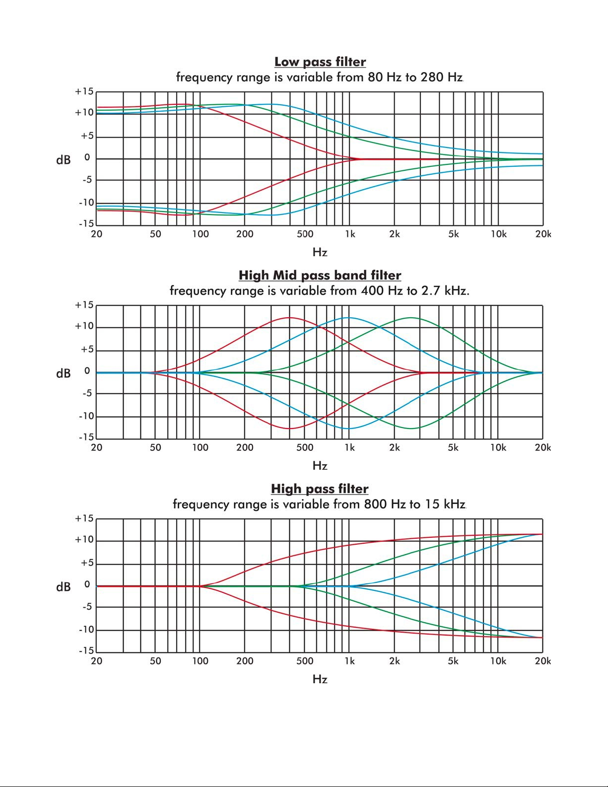
Each in ut contains a arametric equalizer at 4 bands, the gain can be varied within +/- 12dB, and,
in the intermediate bands, the bandwidth (Q) of 1/2 to 2 octaves.
The following diagrams show the filter behavior in question, at different frequencies.

Power su ly: 15 VDC
Signal to noise ratio:> 110dB
Mic Sensitivity: -40dB Out Ref. + 4dBV
Line (mono / stereo) Sensitivity: -20 dB Out Ref. + 4dBV
Maximum out ut signal: + 10dBV
Distortion: <0.02 @ +10 dBV
Total Power consum tion: 450mA
Weight MixLite: 800g
Power Su ly Weight: 330g
Dimensions: 210x150x50 mm. (L * W * H)
© 2004 Charlie Lab All trademarks mentioned are registered Charlie Lab s.r.l. reserves the right to
modify technical and / or aesthetic features of any roduct at any moment and without notice. The
informaction contained in this manual has been checked for accuracy at the time of writing, however,
we do not assume any liability for any included or excluded inaccuracies.
Table of contents


