Charlton & Jenrick Go Eco Bakechef User manual
Clean Air Act Exemption
C&J Go Eco Bakechef stoves have been exempted under the Clean Air Act 1993 to burn seasoned
wood logs in designated smokeless zones in the UK. This is subject to the correct fitting of the air
control plate (the part and fitting instructions are packed separately) maintaining the air wash control
at a minimum opening at all times. Instructions for wood burning MUST be followed in order to
ensure compliance at all times.
Charlton & Jenrick Ltd
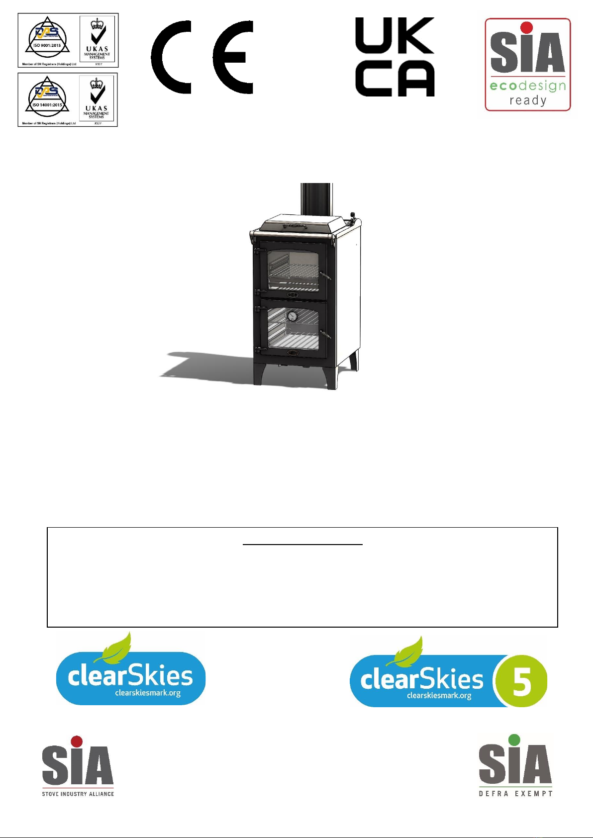
Go Eco Bakechef
Freestanding Woodburning Stove/Cooker Range
5kW Nominal Output.
Charlton & Jenrick Ltd
Unit D Stafford Park 2, Telford, Shropshire, TF3 3AR
T: 01952 200444 F: 01952 200480
A Charlton and Jenrick Group Company
Installation and Operating Instructions
Please hand these instructions to the stove user when the installation is complete. Leave the stove ready
for operation and instruct the user in the correct use of the appliance and operation of controls.
Important: –These products must be installed by a suitably qualified installer.

1Bakechef Range Issue 01 06/21
PLEASE READ ALL THESE INSTRUCTIONS CAREFULLY!
For safety reasons it is essential that your stove is correctly installed and operated. Charlton &
Jenrick cannot accept responsibility for any fault or consequential problems arising through
incorrect installation or operation.
TABLE OF CONTENTS
Section Page No
1. Contents 1
2. Component Identification and Controls 3-4
3. Preparation of Stove for Installation 5
4. Important Safety Information 6
4.1 Warnings and important safety information 6
4.1.1 Instructions 6
4.1.2 Chimney Warning 6
4.1.3 Extractor Fan Warning 6
4.1.4 Cleaning & Chimney Sweeping 6
4.1.5 Fuels 7
4.1.6 Maintenance 7
4.1.7 Ventilation 7
4.2 Health and Safety Information 7
4.2.1 Handling 7
4.2.2 Fire Cement 7
4.2.3 Asbestos 7
4.2.4 Metal Parts 7
5. Installation Information 6
5.1 Chimney & Flue 7
5.2 Ventilation 8
5.3 Flue Draught 8
5.4 Connection to Chimney 8
5.5 Material Clearance Dimensions 9
5.5.1 Distances from Combustible Materials 9
Combustibles above the appliance 9
5.5.2 Distances from Non Combustible Materials 10
5.6 Hearths 10
5.7 Commissioning & Handover 10
6. Technical Data & Declaration of Performance 12
7. Operating Instructions 13
7.1 Safety Notes for your guidance 13
7.1.1 Fireguards 13
7.1.2 Modifications 13
Cont’d………

2Bakechef Range Issue 01 06/21
7.1.3 Overfiring 13
7.1.4 Fume Emission 13
7.1.5 Chimney Fire 13
7.1.6 CO Alarms 13
7.2 Warnings 14
7.3 Clean Air Act (Smoke Control Zones) 14
7.4 Air controls 15
7.4.1 Air Control Operation 15
7.4.2 Air Wash 15
7.4.3 Tertiary Air 15
7.4.4 Wood burning Grate 15
7.4.5 Ashpan 15
7.5 Cleaning 16
7.6 Fuels 16
7.7 Important Notes for Wood Burning 16
7.7.1 Refuelling on to a low Firebed 17
7.7.2 Fuel Overloading 17
7.7.3 Operation with Door Left Open 17
7.8 Lighting the stove 18
7.9 Re-fuelling 19
7.10 Shutting down 19
7.11 Shutting down for prolonged periods 19
7.12 Hot Plate 19
7.13 Cooking Oven 20
7.14 Firebox Grilling Shelf 20
7.15 User Maintenance 21
8. Maintenance Guide 21
8.1 Removing Door 21
8.2 Removing Fuel Retainer 21
8.3 Removing Baffle Plate 21
8.4 Removing Firebox Liners 21
8.5 Removing Grate 21
8.6 Replacing Ceramic Glass Panel 21
8.7 Replacing Door Seals 22
8.8 Repainting 22
8.9 Stainless Steel Trims 22
8.10 Reassembly 22
8.11 Cleaning the Oven 22
8.12 Cleaning the Hot Plate 22
8.13 Cleaning the Flue Ways 23
8.14 Cleaning Access Points Diagrams 22-23
9. Dimensions 22
9.1 Bakechef Stove Principal Dimensions 22
10. Frequently Asked Questions 27

3Bakechef Range Issue 01 06/21
2.0 Component Identification and Controls
List of Components
Description of Parts Qty
Bakechef Stove Assembly 1
Operating/Service Tool 1
Flue Spigot Collar & Fixings 1
Operating Gloves 1
Flame Grill Shelf for Firebox 1
Flat Oven Shelf 1
Profiled Oven Shelf
1
Fig 2 –Go Eco Bakechef
Stove Assembly.
Fig 1: Operating/service Tool

4Bakechef Range Issue 01 06/21
Air Control (LEFT) “FIRE” Slider.
+to increase burn rate –to reduce.
Air is automatically supplied to the
fire and fire door glass air wash.
Oven Diverter (Right) Slider.
+to increase Oven Temp
–to ignite the fire and reduce Oven
Temp.
Fig 3 –Go Eco Bakechef
Controls for Operation.
Table of contents
Popular Wood Stove manuals by other brands


RAIS
RAIS attika NEXO 100 GAS installation guide

WoodPro
WoodPro WS-TS-1500 owner's manual

Contura
Contura C 586W installation instructions

Palazzetti
Palazzetti EVA GENERAL INFORMATION - WARNINGS - INSTALLATION - MAINTENANCE

Lopi
Lopi 1250 Republic owner's manual

Panadero
Panadero CAPRI 3V Usage and maintenance instructions