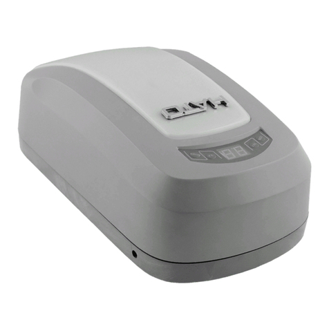
HATO 120 User manual

1
HATO 120/200
AUTOMATION MANUAL
FOR GARAGE DOORS

2
ATTENTION !!!
Please read the manual carefully
before installation and use.
The installation of a new door opener must be carried out
by a technically qualified or licensed person.
Attempting to install or repair a door opener without the
appropriate technical qualifications may result in serious
personal injury, death and / or property damage.

3
Table of Contents
1.Purpose and recommendations.................................................................................. 4
1.1.Purpose ................................................................................................................4
1.2.Recommendations................................................................................................ 4
2.Characteristics.............................................................................................................5
2.1.Device description................................................................................................ 5
2.2.Technical specification.......................................................................................... 6
2.3.Maximum working ranges.................................................................................... 6
2.4.External dimensions............................................................................................. 7
2.5.Elements included in the package:....................................................................... 8
3.Installation ..................................................................................................................9
3.1.Assembly ..............................................................................................................9
3.2.Operation buttons.............................................................................................. 14
3.3.External connector .............................................................................................14
3.4.Checking the corectness of assembly.................................................................15
4.Programming and adjustment ..................................................................................15
4.1.Programming the opening and closing posistions..............................................15
4.2.Adjusting the sensitivity of the overload sensor ................................................15
4.3.Installation of photocells .................................................................................... 16
4.4.Enable/disable auto closing................................................................................ 17
4.5.Gate lock function ..............................................................................................17
4.6.Programming the remote control.......................................................................17
4.7.Final steps........................................................................................................... 17
5.Environmental Protection......................................................................................18
6.Mintenance...............................................................................................................18
7.Troubleshooting........................................................................................................19
8.Recommendations for users .....................................................................................21
9.Emergency gate opening and closing .......................................................................21

4
Thank you for purchasing a sectional door drive designed to operate garage doors. These
installation and operating instructions must be read, understood and observed by the person
installing, operating and maintaining the drive..
1. Purpose and recommendations
1.1. Purpose
Sectional door drive is designed to open and close overhead garage doors in buildings.
1.2. Recommendations
•In accordance with the provisions of the Machinery Directive 2006/42 / EC, it is declared
that the product may not be put into operation until the final machine, into which it is built
or a subassembly of which it is built, obtains a declaration of compliance with the directives
and relevant regulations, which the final machine must meet.
•Installation must be performed by qualified personnel and in accordance with the
regulations in force.
•For the time of installation or service, secure the place of work against the entry of
unauthorized persons, especially minors and children.
•Before starting the installation, check the condition of the gate: it should not sway
excessively, it should move easily and smoothly. To do this, it must be opened and closed
manually.
•To avoid electric shock, always disconnect the drive from the mains before removing its
cover and starting repair or maintenance.
•The remote controls should be kept out of the reach of children to avoid accidental
activation.
•Do not walk or drive through the door while it is closing or opening.
•To avoid accidents, the doors should only be operated when they are within sight of the
actuator.
•The manufacturer reserves the right to change the design of the drive, and thus the
technical specifications, without prior notice.
•Check that the socket from which the drive will be powered has a ground connection and is
installed in an easily accessible place.
•The control buttons and the red emergency release knob must be more than 1.5 meters
high.
•The use of the products must be in accordance with their intended purpose. Any other use
is dangerous. The manufacturer is not liable for any damage caused by improper
installation, application or use.
•Children may not use the drive.
•People with limited sanity, with mental illness, with mental retardation cannot operate the
drive.
PURPOSE ND RECOMMENDATIONS

5
2. Characteristics
2.1. Device description
The drive is designed to operate overhead garage doors. The control panel regulates and provides
efficient operation of all functions such as automatic lighting control, memory, closing, reversing,
photocell function, ensuring efficient operation.
When using the gate, the light automatically turns on and goes off after 3 minutes.
The drive's control unit remembers the programmed end settings of the gate, and the unique braking
system, which reduces the speed of the gate's movement at the end positions, ensures quiet and
trouble-free operation. If the door encounters an obstacle while closing, it reverses automatically.
The control panel has a LOCK security system that prevents accidental remote opening of the gate.
In the event of a power cut, the release lever allows you to manually open and close the door. You
can also use the battery for emergency power. The drive has a special connector for its connection
and a charging system. Automated control unit and coding system (rolling code) allows you to
connect up to 25 control devices (pilots). The drive can also be controlled by a wall switch (optional).
A special emergency lock with a rope is used for emergency opening of the gate from the outside.
Switch, emergency lock with rope, battery and infrared photocells are not included
CHARACTERISTICS

6
2.2. Technical specification
HATO 120
HATO 200
Power
230V AC 50HZ
230V AC 50HZ
Engine
24V DC 80W
24V DC 120W
Standby power consumption
<4W (without
accessories)
<4W (without accessories)
Thrust
600N
1000N
Remote control range
Up to 30m
Up to 30m
Working temperature
-20°C - +50°C
-20°C - +50°C
Linear speed
0,1m/s
0,1m/s
Radio receiver frequency
433,92 MHz
433,92 MHz
Remote
HATO rolling code
(CR2032 battery - 1 pc *)
HATO rolling code (CR2032
battery - 1 pc *)
Garage lighting time
3 minutes
3 minutes
Fuse type
2,5A/250V
2,5A/250V
Level of security
IP30
IP30
Operating time factor
S3 25%
S3 25%
* The manufacturer reserves the right to change the model and number of pilots attached to the
HATO 120/200 engine set
2.3. Maximum working ranges
The length of the
guide
3,3m
3,6m
3,9m
Drive working range
2,4m
2,8m
3,1m
TECHNICAL SPECIFICATION

7
2.4. External dimensions
30mm
150mm
370mm
210mm

8
2.5. Elements included in the package
1. DRIVE HEAD
2. GUIDE DRIVE CHAIN
3. DISENGAGEMENT
4. DRIVE HEAD BRACKETS X2
5. GUIDE WALL BRACKET
6. GATE BRACKET (TWO ELEMENTS)
7. ARM L
8. STRAIGHT ARM
9. ANGLE (OPTIONAL)
10. BOLT KIT
11. REMOTE CONTROL X2
*The manufacturer reserves the right to change the pattern of the remote control included in the
set

9
3. Installation
ATTENTION !
Before starting the assembly, make sure that all the recommendations of section 1.2 are met
3.1. Assembly
Step 1.
Check that the door is well balanced and free to move by manually opening and closing it. Make
sure the center section of the wall above the door is strong enough to support the wall bracket.
Close the door. Measure the door width, mark the center with a pencil, then draw a line down the
door and up on the wall above it. Check the height at which the drive should be mounted. To do this,
slowly open the garage door and observe when the door reaches its highest point in its movement.
Close the door again and mark this point on the wall. Then draw it on the wall a horizontal line
crossing the vertical center line approximately 40 mm above the highest marked point. (Note: the
distance from the horizontal line to the ceiling should be 80mm. If there is not enough space, please
use the maximum possible height that allows you to properly fix the wall bracket.)
INSTALLATION

10
Attach the wall bracket above the
garage door with the center line
through the door aligned with the
center of the bracket. The bottom edge
of the bracket should be level with the
horizontal line. Attach the bracket with
expansion bolts.
Step 2.
Place the shuttle in the groove of the drive
chain guide (make sure it points with the
manual arm towards the drive). Tighten the 4
screws (M6 x 22mm).
In the case of a split guide, first put it together.
To do this, put the attached connector on the
place of dividing, and finally with the screw
and spring we put on the end of the guide. We
regulate the chain tension. The chain should
sag slightly but should not rub against the
guide bar.
Step 3.
Place the motor head on the floor with
cardboard underneath it so as not to scratch
the head. Place the drive against the drive chain guide, making sure that the drive spindle fits into
the guide, then fasten the drive brackets.

11
Step 4.
Close the door.
Place the drive unit in the center of the floor. Lift the front end of the runner up to the wall bracket
that is fitted above the garage door. Insert bolt and lock with nut.
M8 EXPANSION BOLTS
(NOT INCLUDED IN THE SET)
GUIDE END
WALL MOUNT
WALL MOUNTING
SCREW WITH A GUIDE

12
Step 5.
Lift and support the operator with a ladder at such a height that the guide is horizontal and aligned
with the center line drawn on the door. Secure the drive to the ceiling with the mounting brackets
(not included) and the angle bar, always making sure it is level. If necessary, check that the door does
not touch any part of the guide by opening and closing it by hand

13
Step 6.
Attach the door bracket to the top of the door with M8 x 55mm bolts and M8 bolt nuts. Connect the
L arm to the door bracket with the pin and the split pin. Connect the straight arm to the shuttle with
the pin and split pin, then connect the L arm to the straight two M8 x 16mm bolts and nuts, making
sure the door can move freely..
DEBITEUSE - DISENGAGEMENT
STRAIGHT ARM (M6x12 x2 screw)
BROKEN ARM (M6 x2 nut)
DOOR BRACKET
MANUAL
OPERATION
DOOR SUPPORT
FIXING TO A DOOR
- M8 x 55mm x2 SCREWS
- NUT M8 x2
FASTENING THE BREAKING ARM
- PIN AND PIN

14
NUT ADJUSTING THE
CHAIN TENSION
Manual operation
If it is necessary to manually operate the door due to a power cut or failure of the automatic system,
pull the release cord and open / close the door. To reconnect the door to the automatic system, slide
the door until it engages again with the shuttle. If the entrance to the garage is possible only through
the gate, it is necessary to use an emergency lock with a rope (option available at an additional cost).
Chain tension
Attention! Check chain tension. The chain
should hang slightly. Chain tension that is too
tight can damage the drive.
3.2 Operation buttons
(1) Programming button (SET).
Confirm and enter
(2) Remote control programming button (LEARN).
Set a remote control code
(3) UP button.
Programming the settings
(4) DOWN button.
Programming the settings
3.3 External connector
(1) (1) GDN & PB: to connect a `` bell '' type wall button (one contact of the button is connected
to the GDN, the other to the PB)
(2) 24V & GND & PE: for connecting photocells (GND & 24V - power supply)
GDN & PE: output contacts of the photocell receiver in NC mode
Before making any connections on the board, disconnect the power supply
button
photocells
earthing

15
3.4 Checking the correctness of assembly
After all cables are connected, the mechanism should be checked and tested.
1) Check that the arm works well and the door does not jam and does not fall out of the
guides.
2) Connect the power. As soon as the device is turned on, the 7-segment display will show
numbers from 9 to 0 and the bulb will turn on for 2 seconds. After the bulb goes out, the
display will show the sign '' - '' which means that the end positions should be
programmed. If the '' ׀׀ '' sign appears, it means that the end positions have been
programmed (they must be set anew for each gate).
3) After programming, check that the safety devices such as photocell and obstacle stop are
working properly. This very important test must be performed carefully, as the safety of
using the gate depends on the efficient operation of these devices. The overload sensor
contributes significantly to minimizing damage, but only the correct installation of the
photocells will ensure that the door can be stopped before it hits a person or vehicle. This
operation must be performed after programming the drive.
4. Programming and adjustment
4.1 Programming the opening and closing positions
•Press and hold the SET button until the display shows the number 1.
•Press and hold the UP button until the door is fully open.
•Press the SET button, the display will show the number 2.
•Press and hold the DOWN button until the door is fully closed. Releasing the DOWN button
should take place at the moment of touching the door to the threshold. Do not set the end
position to the so-called "pressure", because in normal operation the drive slows down
before the end position and may not reach such a set position and will not react until the
end positions are correctly set.
•Press the SET button to complete programming. The door will open and close automatically.
After closing, the display should show '' || '' If `` - '' appears, repeat programming, paying
attention to the above point.
•The door open and close positions have been set.
WARNING! Objects and people should not be near the gate during installation.
IMPORTANT! To ensure continued safety, safety systems should be checked regularly.
4.2 Adjusting the sensitivity oft he overload sensor
•If necessary, the maximum engine power may only be adjusted by a qualified mechanic.
•Press and hold the SET button until the display shows the number 3, release the button. The
device is in force regulation mode and shows the amount of force set.
•Press the UP button to increase the force by one step, press DOWN to decrease it one step.
The maximum rank is 9, the minimum rank is 1.
•Press the SET button to confirm the setting.
If it encounters an obstacle when closing the door, it will move back 15-20 cm.

16
4.3 Installation of photocells
Before setting the photocell function, make sure that the device is properly installed. The receiver
of the photocells must work in the NC mode - if there is no obstacle between the transmitter and
the receiver, the receiver's output contacts should be closed.
(1) Press and hold the DOWN button, the mark will appear on the display
" - " , followed by " H " or " | | "
" H " means that the drive supports the photocells
" | | " means that the drive does not react to the photocells
(2) Pressing the UP button activates the photocells (" H " lights up )
Pressing the DOWN button disables the photocells support ("| |" is lit)
(3) After setting the correct option, press the SET button and the system enters the normal
operation mode
Installing photocells prevents the gate from closing when there is an obstacle in its light (eg a car).
Use photocells specifically designed for garage doors.
4.4 Enable/disable auto closing.
(1) Press and hold the UP button, the display will show "-" followed by a number from 0 to 9.
(2) Pressing the UP button once extends the auto-close time by one minute. Pressing the DOWN
button once reduces the closing time by one minute. The current closing time is shown on
230 Vac
network
EMERGENCY
POWER SUPPLY
BATTERY
24Vdc
PHOTOCELL
TRNSMITTER
RECEIVER
SEQUENTIAL
CONTROL
MONOSTABLE
BUTTON

17
the display.
(3) The auto-close function is disabled when the auto-close time is 0.
(4) Press the SET button to confirm and exit.
4.5 Gate lock function
The gate lock function (LOCK system) protects against accidental opening (e.g. after putting the
remote control in your pocket). After activating this function, the gate can be opened only after
pressing the lock button on the remote control (it is a button that cannot be programmed to operate
the drive - button code 3), and then the appropriate button (directly after itself). To activate the gate
lock function:
(1) Press and hold the SET button, the display will show a number from 1 to 4. Release the
button. The display will show '' 0 '' or '' 1 ''.
(2) Press the UP button, the display will show the number 1 - the door locking function is
active. Press the DOWN button, the display will show the number 0 - the blocking function
is inactive.
(3) After setting the correct option, press the SET button and the system enters the normal
operation mode.
4.6 Programming the remote control
•Press the LEARN button - a dot will light up on the display. Then press the selected button on
the remote control twice. The dot should blink and the drive will go into normal operation.
The button on the remote control has been programmed.
•Repeat the above for all remotes. You can program up to 20 transmitters or buttons.
•To clear all memorized remotes, press and hold the LEARN button for more than 8 seconds
until the display shows C. All remotes have been cleared.
•The button code 3 cannot be used to operate the drive - it serves only for the blocking
function (the button generating the code 3 may be described differently on the remote
control housing).
4.7 Final steps
•Check that all bolts and nuts are tightened.
•Check that the control button and the emergency release knob are installed above a height
of 1.5 meters
•Check that the installation has been carried out in accordance with the applicable regulations
•Check the effectiveness of the safety and control devices.
•Check the balance of the garage door leaf.
•Carry out multiple attempts to close and open the garage door to make sure that all
mechanisms are working properly. Maintain the ratio of working time to rest time in the
proportion of 1: 2. Operating the drive without adequate idle time may result in damage.
•Check the effectiveness of the protective circuit of the residual current system.
•Mark the garage door with appropriate signs in potentially dangerous places.
•Stick a sticker on the door in a visible place with the text Warning!

18
5. Environmental protection
Disposing of packaging:
Packaging elements (cardboard, plastic, etc.) are classified as solid waste suitable for
recycling. Before disposing of the packaging, please check the local regulations for the material in
question.
Device scrapping:
The product consists of many types of different materials. Most of the materials used (aluminum,
plastic, steel, tubing, etc.) can be disposed of in normal recycling bins. Other materials (control units,
remote control batteries, etc.) may contain harmful substances and should be returned to
specialized companies for disposal.
6. Maintenance
In order to ensure the greatest possible safety measures and to extend the service life of all
components of the set, the user should perform maintenance on the drive once a month.
These are the maintenance operations while the power is off:
• disconnect the drive from the power supply
• check the condition of the garage door and the chain, especially in terms of stability
• metal, moving parts of the drive should be regularly lubricated to prevent their rusting and
to ensure failure-free operation of the device.
• clean the photocell housings with a damp cloth. Do not use solvents or any other chemical
products that may damage the device
• before changing the bulb, the device should be disconnected from the power source
• If the chain squeaks, lubricate it with chain oil
• maintenance activities must always be carried out according to the manufacturer's
recommendations

19
7. Troubleshooting
PROBLEM
POSSIBLE CAUSES
SOLUTIONS
Nothing is displayed on
the LED display. The gate
is down.
1. No power
1. Make sure the power is on
2. Blown fuse
2. Check the fuse and, if necessary,
replace it with a new one (2.5A)
After turning the supply
on, the drive does not
carry out the test (the
digits should change from
"9" to "1") the display
shows a different
character.
Defective microcontroller
Send the drive to the service with a
description of the fault and the
purchase document
The sign appeared on the
LED display
Photocells support function
enabled, no photocells
connected
Connect the photocells or disable
the photocell support function.
The gate moves slightly
End positions not set
Program the end positions anew in
accordance with the instructions
The selected button on
the remote control cannot
be logged in
1. The selected button is used
for the lock function
1. Select a different button for
logging in
2. Defective remote control
2. Send the remote control to the
service together with a description
of the fault and the purchase
document
After programming the
end position, the actuator
is inoperative
1. End positions incorrectly
set (LED displays "-").
1. Re-program the end positions.
Please note that we set the top
position first, and then the bottom
position. Neither position can be
set to pressure.
2. The gate lock function has
been activated (the display
shows "||" and yet the drive
does not work)
- if switching on the blocking
function was accidental, turn this
function off
- if the activation of the lock
function was intentional, first press
the button "3" on the remote
control and then the one that is
logged in.
3. Remote control button for
the drive not logged in
3. Log the remote control into the
drive according to the instructions.
The door opens but does
not close
1. The photocells support
function is enabled but the
photocells are not installed
1. Disable the photocell operation
function according to the
instructions
2. The path of infrared rays
has been interrupted
2. Remove the obstacle
3. Faulty photocells
3. Send the photocells to the
service together with a description
of the fault and the purchase
document
4. Insufficient drive force
4. Set the correct drive force in

20
accordance with the instructions
and standards.
When closing, the gate
stops suddenly and moves
backwards
1. Increased resistance to
door sliding
1. Unblock the drive and, by
manually moving the gate, check
that the gate moves easily and that
it is well balanced with springs.
2. Insufficient drive force
2. Set the correct drive force in
accordance with the instructions
and standards.
When closing the door,
the drive does not react
to the obstacle in the light
of the photocells
Incorrect photocells
If the gate is open and we cover
the photocells, the gate will not
close, and if the gate does not
respond to an obstacle, it means
that the photocells are not
compatible with the drive. Suitable
photocells for the HATO 200 model
must be used
The drive moves the gate
in steps of a few
centimeters
Engine speed sensor
defective.
Send the drive to the service with a
description of the fault and the
purchase document
The remote control does
not work
1. Battery discharged
1. Replace the battery
2. The remote control is not
logged into the drive
2. Log in the remote control
according to the instructions
3. Faulty remote control
3. Send the remote control to the
service together with a description
of the fault and the purchase
document
The range of the remote
control is too small
1. Drive located in a steel or
reinforced concrete garage
1. Installation of an external
antenna by a specialist
2. Battery running low
2. Battery replacement
3. Faulty remote control
3. Send the remote control to the
service together with a description
of the fault and the purchase
document
4. Defective radio module in
the drive
4. Send the drive to the service
together with a description of the
fault and the purchase document
After a power failure and
restarting, the drive
automatically moves the
gate
1. Wrong type of wall switch
to control the door
1. To control the gate with a wall
button, a "bell" type button with
normally open contacts should be
used. Replace the button with the
correct one.
2. Defective microcontroller
2. Send the drive to the service
with a description of the fault and
the purchase document
Other problem
Other causes
Send the drive to the service with a
description of the fault and the
purchase document.
This manual suits for next models
1
Table of contents
Other HATO Garage Door Opener manuals
Popular Garage Door Opener manuals by other brands

CAME
CAME VER-PLUS Series installation manual

Vicway
Vicway VT 1000E Installation instructions and user guide

Chamberlain
Chamberlain 8360 manual

Chamberlain
Chamberlain Power Drive Security+ PD612CDM owner's manual

Chamberlain
Chamberlain B500 owner's manual

Homentry
Homentry HE60R Installation and operating instructions