Chatsworth Products 37212-260 User manual

CPI KVM Switch
User Manual
Version 1.0
12/2016
©2016 Chatsworth Products, Inc. All rights reserved. CPI, CPI Passive Cooling, MegaFrame,
Saf-T-Grip, Seismic Frame, SlimFrame, TeraFrame, GlobalFrame, Cube-iT Plus, Evolution,
OnTrac, QuadraRack and Velocity are federally registered trademarks of Chatsworth
Products, Inc. Simply Efficient is a trademark of Chatsworth Products, Inc.
All other trademarks belong to their respective companies. Rev.2 12/16 MKT-60020-530

2
Table of Contents
Legal Information .............................................................................................................................. 3
Warranty ........................................................................................................................................... 3
Introduction ............................................................................................................ 4
Product Features – IP KVM Switch with DB15 Ports (P/N 37212-260) ........................................... 5
Product Features – Analog KVM Switch with DB15 Ports (P/N 37202-160) ................................... 6
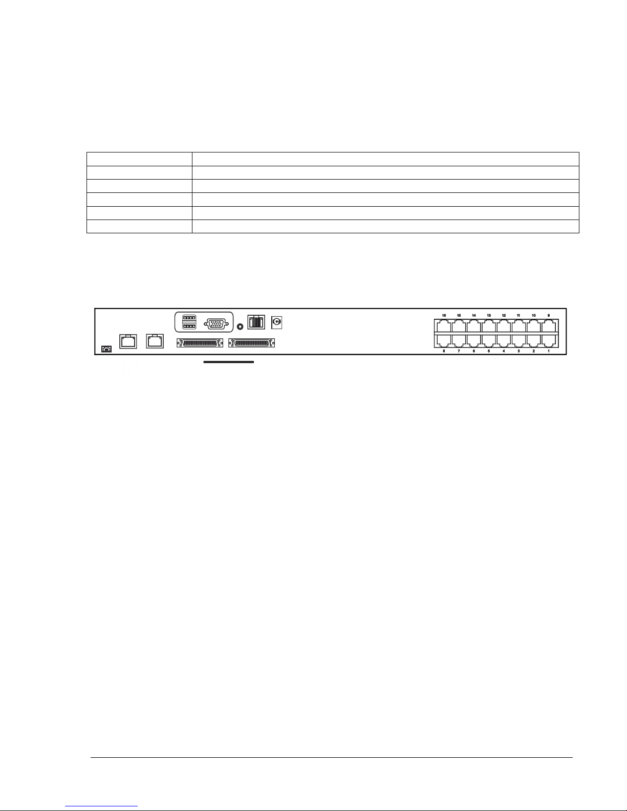
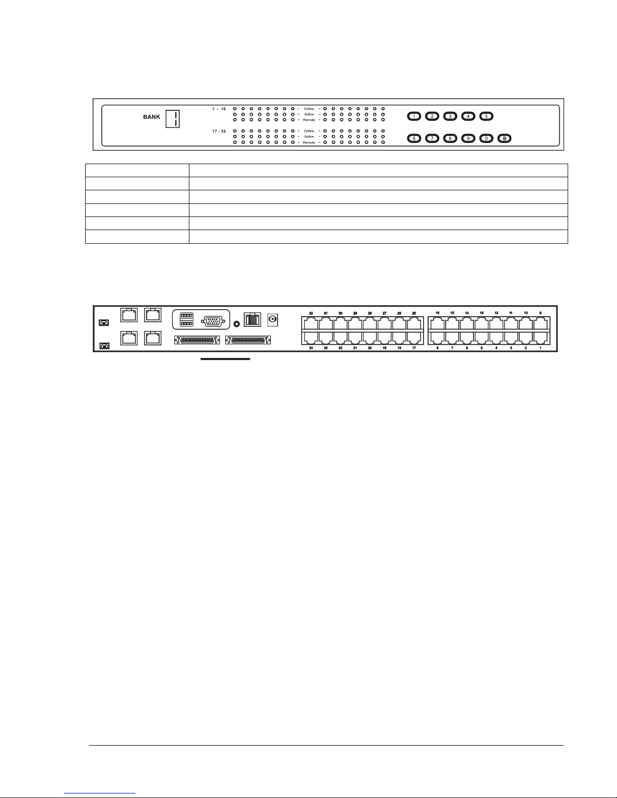
Product Features – IP KVM Switch with Cat5/6 Ports (P/N 37207-360, 37207-420) ...................... 7
Product Features – Analog KVM Switch with Cat5/6 Ports (P/N 37210-260, 37210-220) ............ 10
Important Safeguards .......................................................................................... 13
Safety Instructions .......................................................................................................................... 13
Federal Communications Commission (FCC) Regulatory Notices ................................................ 14
Installation ............................................................................................................ 15
Unpacking – Package Contents ..................................................................................................... 15
Rack/Cabinet Installation ................................................................................................................ 16
Cable Diagram for KVM Switches with DB15 Ports ....................................................................... 17
Cable Diagram for KVM Switches with Cat5/6 Ports ..................................................................... 18
Server Connections for KVM Switches with Cat 5/6 Ports ............................................................ 19
VGA-USB Dongle (P/N 37208-103, 37208-803, 37208-603) ........................................................ 19
VGA-PS/2 Dongle (P/N 37208-104, 37208-804, 37208-604) ........................................................ 19
Remote Console Connection for KVM Switches with Cat5/6 Ports ............................................... 20
Cascade – Expansion for KVM Switches with DB15 Ports ............................................................ 21
Cascade – Expansion for KVM Switches with Cat5/6 Ports .......................................................... 22
Use – KVM Switch ................................................................................................ 23
Power On ........................................................................................................................................ 23
Password Configuration for the Local/Remote Console ................................................................ 24
The On-Screen Display (OSD) Menu ............................................................................................. 25
The F1 Main Menu ......................................................................................................................... 26
Local Console Hotkeys ................................................................................................................... 27
Remote Console Hotkeys............................................................................................................... 27
Set-Up – IP Console ............................................................................................. 28
Troubleshooting Guide – KVM Switch .............................................................. 30
Appendices ........................................................................................................... 31
Factory Default Setting ................................................................................................................... 31
FAQ ................................................................................................................................................ 31
Specifications – KVM Switch with DB15 Ports ............................................................................... 33
Specifications – KVM Switches with Cat5/6 Ports ......................................................................... 34
Accessories for KVM Switches with DB15 Ports ........................................................................... 35
Accessories for KVM Switches with Cat5/6 Ports .......................................................................... 36

3
Chatsworth Products, Inc.
29899 Agoura Road, Suite 120
Agoura Hills, CA 91301
800-834-4969
CPI KVM Switch User Manual
©2011 Chatsworth Products, Inc. All rights reserved.
Legal Information
The information contained in this guide is subject to change without notice.
Chatsworth Products, Inc. shall not be liable for technical or editorial errors or omissions
contained herein; nor is it liable for any injury, loss, or incidental or consequential damages
resulting from the furnishing, performance, or use of this material and equipment.
Warranty
To review Chatsworth Products, Inc. (CPI’s) Standard Limited Warranty, click here.

4
Introduction
This document is the User’s Manual for KVM Switches from Chatsworth Products, Inc. (CPI).
It guides the user through installation, operation and maintenance of the equipment.
The KVM Switch is a standalone, rack-mount keyboard, video and mouse switch that allows
multiple server computers to be accessed using a single set of rack-mount peripherals. Some
models also support access for a remote computer and/or an Ethernet connection.
The table below lists the CPI Part Numbers for the standalone KVM Switches covered by this
manual. There is a separate manual for the 17” LCD KVM Drawers and Switches.
Part Numbers Covered in this Manual
Related Products
(Standalone)
Standalone
KVM Switch
KVM Switch
Description
LCD KVM
Drawer
LCD KVM Drawer
and Switch
DB15 ports
37212-260
IP KVM Switch, with 16 DB15 ports,
and
1 Local, no Remote, 1 IP Console
37200-111
37209-261
37200-112
37209-262
37202-160
Analog KVM Switch, with 16 DB15
ports, and 1 Local, no Remote, no IP
Console
37200-111
37203-161
37200-112
37203-162
37201-111
37204-161
37201-112
37204-162
Cat5/6 ports
37207-360
IP KVM Switch, with 16 Cat5/6 ports,
and 1 Local, 1 Remote, 1 IP Console
37200-111
37205-361
37200-112
37205-362
37201-111
37206-361
37201-112
37206-362
37207-420
IP KVM Switch, with 32 Cat5/6 ports,
and 1 Local, 1 Remote, 2 IP Consoles
37200-111
37205-421
37200-112
37205-422
37201-111
37206-421
37201-112
37206-422
37210-260
Analog KVM Switch, with 16 Cat5/6
ports, 1 Local, 1 Remote, no IP
Console
N/A
N/A
37210-220
Analog KVM Switch, with 32 Cat5/6
ports, 1 Local, 1 Remote, no IP
Console
N/A
N/A
Note that there are four basic configurations: Analog or IP switches with DB15 or Cat5/6
computer ports. Analog switches provide local only connections and are accessed using rack-
mount peripherals or a connected remote computer terminal. IP switches include an Ethernet
connection and can also be accessed through the IP network using a Java-enabled web
browser.
DB15 computer ports use a proprietary cable for computer connections and must be located
close to the computers. Cat5/6 computer ports use standard Cat5/6 UTP cables with RJ45
connectors to attach to computers. A dongle (ordered separately) is used to connect the
computer, which can be located up to 132 feet (40 meters) away from the KVM switch.

5
Product Features – IP KVM Switch with DB15 ports (P/N 37212-260)
16 DB15 KVM switch device ports which provide low-level keyboard, video and mouse
connectivity to equipment within a rack. KVM Switches with DB15 ports use a proprietary 6
feet (1.8 meters) or 10 feet (3.0 meters) long breakout cable to connect computers. Cables
are purchased separately (P/N 37203-161 or 37208-111).
Buttons on the front panel allows easy switching between computer ports. LED indicators on
the front panel to show if the computers are connected and powered on and which port is
selected. Users can also switch between ports using an intuitive on-screen display menu or
using keyboard hot keys.
A local console to connect external peripherals, like the 17” LCD KVM Drawer (P/N 37200-
11X or 37201-11X). Access to the switch can be password protected for eight user
accounts.
An IP console that provides remote management capability for one user over a 10/100
TCP/IP network. Users access equipment through a Java-compatible web browser, like
Microsoft Windows Internet Explorer, using a password protected logon and switch between
computers using an intuitive on-screen menu. Supports fifteen user accounts.
An expansion connection that allows up to eight switches to be connected together
(cascade) providing access to 128 computers from the Local Console or IP Console on the
first switch. KVM Switches with DB15 ports use a proprietary cascade cable to connect
together (P/N 37208-162). No device ports are used. KVM Switches with DB15 ports will not
connect to KVM Switches with Cat5/6 ports.
Front Panel - 16 Port IP KVM Switch with DB15 ports (P/N 37212-260)
Bank no.
7-Segment BANK LED indication
PC port LEDs
Online: Blue LED indicates a PC is connecting to the port
Active: Green LED indicates a selected channel
Channel button
Press to select from 01 to 16 (KVM ports)
Bank button
Select the bank from 1 to 8 (Expansion switches)
Rear Panel - 16 Port IP KVM Switch with DB15 ports (P/N 37212-260)
1 local console, no remote console, 1 IP console, 16 DB15 server connections, 1 DB15
expansion (cascade) connection (use Cascade Cable P/N 37208-162)

6
Product Features – Analog KVM Switch with DB15 ports (P/N 37202-160)
Used primarily as expansion switches for other KVM Switches with DB15 ports and 17” LCD
KVM Drawer and Switches with DB15 ports.
16 DB15 KVM switch device ports which provide low-level keyboard, video and mouse
connectivity to equipment within a rack. KVM Switches with DB15 ports use a proprietary 6
feet (1.8 meters) or 10 feet (3.0 meters) long breakout cable to connect computers. Cables
are purchased separately (P/N 37208-161 or 37208-111).
Buttons on the front panel allows easy switching between computer ports. LED indicators on
the front panel to show if the computers are connected and powered on and which port is
selected. Users can also switch between ports using an intuitive on screen display menu or
using keyboard hot keys.
A local console to connect external peripherals, like the 17” LCD KVM Drawer
(P/N 37200-11X or 37201-11X). Access to the switch can be password protected for eight
user accounts.
An expansion connection that allows up to eight switches to be connected together
(cascade) providing access to 128 computers from the Local Console on the first switch.
KVM Switches with DB15 ports use a proprietary cascade cable to connect together (P/N
37208-162). No device ports are used. KVM Switches with DB15 ports will not connect to
KVM Switches with Cat5/6 ports.
Front Panel - 16 Port Analog KVM Switch with DB15 ports (P/N 37202-160)
Bank no.
7-Segment BANK LED indication
PC port LEDs
Online: Blue LED indicates a PC is connecting to the port
Active: Green LED indicates a selected channel
Channel button
Press to select from 01 to 16 (KVM ports)
Bank button
Select the bank from 1 to 8 (Expansion switches)
Rear Panel - 16 Port IP KVM Switch with DB15 ports (P/N 37202-160)
1 local console, no remote console, no IP console, 16 DB15 server connections, 1 DB15
expansion (cascade) connection (use Cascade Cable P/N 37208-162)

7
Product Features – IP KVM Switch with Cat5/6 ports (P/Ns 37207-360, 37207-420)
16 or 32 Cat5/6 RJ45 KVM switch device ports which provide low-level keyboard, video and
mouse connectivity to equipment within a rack. KVM Switches with Cat5/6 ports use
standard Cat5/6 UTP cabling with RJ45 connectors and dongles to connect computers,
which allow computers to be located much farther from the switch, up to 132 feet (40
meters) away. Dongles (P/N 37208-103 or 37208-104) are purchased separately.
Buttons on the front panel that allow easy switching between computer ports. LED indicators
on the front panel to show if the computers are connected and powered on and which port is
selected. Users can also switch between ports using an intuitive on screen display menu or
using keyboard hot keys.
A local console to connect external peripherals, like the 17” LCD KVM Drawer
(P/N 37200-11X or 37201-11X). Access to the switch can be password protected for eight
accounts.
A remote console connection that provides access from a separate computer located
nearby. The remote console attaches to the switch using standard Cat5/6 UTP cabling with
RJ45 connectors which allows the computer to be located up to 500 feet (150 meters) away
from the switch.
An IP connection that provides remote management capability for one user over a 10/100
TCP/IP network. Users access equipment through a Java-compatible web browser, like
Microsoft Windows Internet Explorer, using a password protected logon and switch between
computers using an intuitive on screen menu. Supports fifteen user accounts.
An expansion connection that allows up to eight switches to be connected together
(cascade) providing access to 128 or 256 computers from the local, remote or IP consoles
on the first switch. KVM Switches with Cat5/6 ports use a proprietary cascade cable (P/N
37208-165) to connect together. No device ports are used. KVM Switches with Cat5/6 ports
will not connect to KVM Switches with DB15 ports.
See the next two pages for product diagrams.

8
Front Panel - 16 Port IP KVM Switch with Cat5/6 ports (P/N 37207-360)
Bank no.
7-Segment BANK LED indication
PC port LEDs
Online: Blue LED indicates a PC is connecting to the port
Active: Green LED indicates a selected channel
Remote: Orange LED indicates the port is selected by a remote console
Channel button
Press to select from 01 to 16 (KVM ports)
Bank button
Select the bank from 1 to 8 (Expansion switches)
Rear Panel - 16 Port IP KVM Switch with Cat5/6 ports (P/N 37207-360)
1 local console, 1 remote console, 1 IP console, 32 RJ45 (8P8C) server connections, 1
expansion (cascade) connection (use Cascade Cable P/N 37208-165)
Remote
Power
Local
console
out Cascade in
IP

9
Front Panel - 32 Port IP KVM Switch with Cat5/6 ports (P/N 37207-420)
Bank no.
7-Segment BANK LED indication
PC port LEDs
Online: Blue LED indicates a PC is connecting to the port
Active: Green LED indicates a selected channel
Remote: Orange LED indicates the port is selected by a remote console
Channel button
Press to select channel from 01 to 32
Bank button
Select the bank from 1 to 8
Rear Panel - 32 Port IP KVM Switch with Cat5/6 ports (P/N 37207-420)
1 local console, 1 remote console, 2 IP consoles, 32 RJ45 (8P8C) server connections, 1
expansion (cascade) connection (use Cascade Cable P/N 37208-165)
Remote
Local
console
IP 2
IP 1 out Cascade in

10
Product Features – Analog KVM Switch with Cat5/6 ports (P/Ns 37210-260, 37210-220)
Used primarily as expansion switches for other IP KVM Switches with Cat5/6 ports and 17”
LCD KVM Drawer and IP Switches with Cat5/6 ports.
16 or 32 Cat5/6 RJ45 KVM switch device ports which provide low-level keyboard, video and
mouse connectivity to equipment within a rack. KVM Switches with Cat5/6 ports use
standard Cat5/6 UTP cabling with RJ45 connectors and dongles to connect computers,
which allow computers to be located much farther from the switch, up to 132 feet (40
meters) away. Dongles (P/N 37208-103 or 37208-104) are purchased separately.
Buttons on the front panel that allow easy switching between computer ports. LED indicators
on the front panel to show if the computers are connected and powered on and which port is
selected. Users can also switch between ports using an intuitive on screen display menu or
using keyboard hot keys.
A local console to connect external peripherals, like the 17” LCD KVM Drawer (P/N 37200-
11X or 37201-11X). Access to the switch can be password protected for eight user
accounts.
A remote console connection that provides access from a separate computer located
nearby. The remote console attaches to the switch using standard Cat5/6 UTP cabling with
RJ45 connectors which allows the computer to be located up to 500 feet (150 meters) away
from the switch.
An expansion connection that allows up to eight switches to be connected together
(cascade) providing access to 128 or 256 computers from the local, remote or IP consoles
on the first switch. KVM Switches with Cat5/6 ports use a proprietary cascade cable (P/N
37208-165) to connect together. No device ports are used. KVM Switches with Cat5/6 ports
will not connect to KVM Switches with DB15 ports.
See the next two pages for product diagrams.

11
Front Panel - 16 Port Analog KVM Switch with Cat5/6 ports (P/N 37210-260)
Bank no.
7-Segment BANK LED indication
PC port LEDs
Online: Blue LED indicates a PC is connecting to the port
Active: Green LED indicates a selected channel
Remote: Orange LED indicates the port is selected by a remote console
Channel button
Press to select channel from 01 to 16 (KVM ports)
Bank button
Select the bank from 1 to 8 (Expansion switches)
Rear Panel - 16 Port Analog KVM Switch with Cat5/6 ports (P/N 37210-260)
1 local console, 1 remote console, no IP console, 16 RJ45 (8P8C) server connections, 1
expansion (cascade) connection (use Cascade Cable P/N 37208-165)

12
Front Panel - 32 Port Analog KVM Switch with Cat5/6 ports (P/N 37210-220)
Bank no.
7-Segment BANK LED indication
PC port LEDs
Online: Blue LED indicates a PC is connecting to the port
Active: Green LED indicates a selected channel
Remote: Orange LED indicates the port is selected by a remote console
Channel button
Press to select channel from 01 to 32 (KVM ports)
Bank button
Select the bank from 1 to 8 (Expansion switches)
Rear Panel - 32 Port Analog KVM Switch with Cat5/6 ports (P/N 37210-220)
1 local console, 1 remote console, no IP consoles, 32 RJ45 (8P8C) server connections, 1
expansion (cascade) connection (use Cascade Cable P/N 37208-165)

13
Important Safeguards
Please read all of these instructions carefully before you use the device.
Save this manual for future reference.
Safety Instructions
Unplug equipment before cleaning. Don’t use liquid or spray detergent;
use a moist cloth.
Keep equipment away from excessive humidity and heat. Preferably,
keep it in an air-conditioned environment with temperatures not
exceeding 40º Celsius (104º Fahrenheit).
When installing, place the equipment on a sturdy, level surface to
prevent it from accidentally falling and causing damage to other
equipment or injury to persons nearby.
When the equipment is in an open position, do not cover, block or in
any way obstruct the gap between it and the power supply. Proper air
convection is necessary to keep it from overheating.
Arrange the equipment’s power cord in such a way that others won’t trip
or fall over it.
If you are using a power cord that didn’t ship with the equipment, ensure
that it is rated for the voltage and current labeled on the equipment’s
electrical ratings label. The voltage rating on the cord should be higher
than the one listed on the equipment’s ratings label.
Observe all precautions and warnings attached to the equipment.
If you don’t intend on using the equipment for a long time, disconnect it
from the power outlet to prevent being damaged by transient over-
voltage.
Keep all liquids away from the equipment to minimize the risk of
accidental spillage. Liquid spilled onto the power supply or on other
hardware may cause damage, fire or electrical shock.
Only qualified service personnel should open the chassis. Opening it
yourself could damage the equipment and invalidate its warranty.
If any part of the equipment becomes damaged or stops functioning,
have it checked by qualified service personnel.
Slide rail mounted equipment is not to be used as a shelf or a
workspace.

14
Federal Communications Commission (FCC) Regulatory Notices
This equipment has been tested and found to comply with the limits for a Class B digital device,
pursuant to Part 15 of the FCC rules. These limits are designed to provide reasonable
protection against harmful interference in a residential installation.
Any changes or modifications made to this equipment may void the user’s authority to operate
this equipment. This equipment generates, uses, and can radiate radio frequency energy and, if
not installed and used in accordance with the instructions, may cause harmful interference to
radio communications.
However, there is no guarantee that interference will not occur in a particular installation. If this
equipment does cause harmful interference to radio or television reception, which can be
determined by turning the equipment off and on, the user is encouraged to try to correct the
interference by one or more of the following measures:
Re-position or relocate the receiving antenna.
Increase the separation between the equipment and receiver.
Connect the equipment into an outlet on a circuit different from that to which the receiver is
connected.

15
Installation
Unpacking/ Package Contents
Standalone KVM Switches come with the parts shown below. Check and make sure they are
included and in good condition. If anything is missing or damaged, please contact the supplier
immediately.
Items 7-10 are only included with KVM Switches (P/Ns 37207-XXX, 37210-XXX).
KVM Switch
Remote Receiver Kit
1. LCD KVM Switch x 1 pc
7. Remote receiver x 1 pc
2. Screw, M3 x 4.5 mm x 2 pc
8. Combo KVM Cable x 1 pc
3. Screw, M4 x 10mm x 8 pc
9. Power adapter x 1 pc
4. Mounting Brackets x 1 set
10. Power cord x 1 pc
5. Power adapter x 1 pc
(Not included with P/N 37202-160)
6. Power cord x 1 pc

16
Rack/Cabinet Installation
Attach the rack-mount brackets to the KVM switch using the included screws.
Attach the switch to a rack or cabinet. Rack-mount hardware is not included with the switch.

17
Cable Diagram for KVM Switches with DB15 ports
Each server connects to the KVM Switch with DB15 ports with a Combo KVM Cable
(P/N 37208-161 or 37208-111), ordered separately. Order one Combo KVM Cable per server.
Combo KVM Cables are available in two lengths and are sold individual, in packages of eight
and in packages of 16.
Note: Analog KVM Switch (P/N 37202-160) does not have IP connections.

18
Cable Diagram for KVM Switches with Cat5/6 ports
Each server connects to the KVM Switch with Cat5/6 ports with a Cat5/6 UTP cable that has
RJ45 connectors and an IP KVM Cable Dongle. Order one IP KVM Cable Dongle per server to
match the server’s keyboard and mouse type: PS/2 (P/N 37208-104) or USB (P/N 37208-103).
The switch also has a remote console connection and includes the receiver and cables for
attaching the remote computer. All switches have local consoles. Some switches also have IP
consoles.
Note: The diagram above shows IP KVM Switch P/N 37207-420, which has 32 server ports, 1 local
console, 1 remote console and two IP consoles. Other switches have different numbers of server ports
and IP consoles. P/N 37210-220 has no IP consoles. P/N 37207-360 has 16 server ports and 1 IP
console. P/N 37210-260 has 16 server ports and no IP consoles. Refer to pages 7 through 12 for features
and diagrams of the other switches.

19
Server Connections for KVM Switches with Cat5/6 ports
Servers connect to the KVM Switches with Cat5/6 ports using a dongle that makes the
connection between the server’s video, keyboard and mouse connections and the UTP cable
from the switch. Order the dongle to match the server’s video, mouse and keyboard connection.
VGA-USB dongle (P/N 37208-103, 37208-803, 37208-603)
Connect server with DB15 video connector and USB mouse and keyboard to the UTP cable
from the KVM Switch with Cat 5/6 ports.
Sold individually (P/N 37208-103), in packs of eight (P/N 37208-803) and in packs of 16
(P/N 37208-603)
VGA-PS/2 dongle (P/N 37208-104, 37208-804, 37208-604)
Connect server with DB15 video connector and PS/2 mouse and keyboard to the UTP cable
from the KVM Switch with Cat 5/6 ports.
Sold individually (P/N 37208-104), in packs of eight (P/N 37208-804) and in packs of 16
(P/N 37208-604)

20
Remote Console Connection for KVM Switches with Cat5/6 ports
Each KVM switch with Cat5/6 ports also has one remote console connection and includes a
remote console receiver to connect a separate set of peripherals or computer for switch
access. Connect the remote console with a Cat5/6 UTP cable.
This manual suits for next models
5
Table of contents
Popular Switch manuals by other brands

ABB
ABB UC Series Maintenance Guide

SMA
SMA Enwitec Sunny Island 4.4M manual

QSFPTEK
QSFPTEK S5600-24T8X quick start guide

Key Digital
Key Digital Champion SeriesKD-2x1CSK operating instructions

NetPing
NetPing GB322 user guide

Brocade Communications Systems
Brocade Communications Systems ICX 6430-C installation instructions