Chauvin Arnoux K Series User manual

F R A N Ç A I S
E N G L I S H
D E U T S C H
I T A L I A N O
Notice de fonctionnement
User's manual
Bedienungsanleitung
Manuale d’uso
Manual de instrucciones
K series
A100 series
MA100 series
MA200 series
Adaptateur secteur
Mains adapter
Netzadapter
Adattatore rete electrica

PR CAUTIONS D’EMPLOI
inammables.
pour mise au rebut.
Respectez les conditions environnementales d’utilisation.
CAT GORIES DE MESURE
tension.
Exemple : tableau de distribution, disjoncteurs, machines ou appareils industriels fxes.

English .......................................................................................................................... 7
Deutsch ...................................................................................................................... 12
Italiano ........................................................................................................................ 17
...................................................................................................................... 22
θ130°C
SOMMAIRE
1. PR SENTATION .............................................................................................................................4
2. UTILISATION ..................................................................................................................................4
3. CARACT RISTIqUES ...................................................................................................................5
........................................................................................... 5
. ...............................................................................................5
. Conditions d’environnement ...............................................................................................5
.............................................................................5
4. ENTRETIEN ....................................................................................................................................5
5. R PARATION .................................................................................................................................6
6. GARANTIE ......................................................................................................................................6
7. POUR COMMANDER ....................................................................................................................6
adaptateur secteur et nous vous remercions de votre confance.
Pour obtenir le meilleur service de votre appareil :
lisez attentivement cette notice de onctionnement ;
Fusible thermique.
Courant continu.
Courant alternati.

4
1
2
1. PR SENTATION
2. UTILISATION
3. Retirez la pile.
(Figure ci-dessus, rep.2) ;
2. Positionnez le commutateur sur OFF ;
(Figure ci-dessus, rep.1).

5
3. CARACT RISTIqUES
3.1 CARACT RISTIqUES CONSTRUCTIvES
coque rigide plastique noir
Dimension 103 x 64 x 28 mm
Masse 200 g environ
3.2 CARACT RISTIqUES LECTRIqUES
230 V AC / 50 Hz / 30 mA AC / 6,9 V A
Sortie 9 V DC / 150 mA DC / 1,35 W
3.3 CONDITIONS D’ENvIRONNEMENT
Utilisation
2
Altitude < 2000 m
3.4 CONFORMIT AUx NORMES INTERNATIONALES
V
Remarque :
Types d’appareils
300 V CAT II
600 V CAT III
FLEX A100
4. ENTRETIEN

5. R PARATION
votre distributeur.
6. GARANTIE
Notre garantie s’exerce, sau stipulation expresse, pendant douze mois
:
;
abricant ;
;
;
7. POUR COMMANDER
la notice de onctionnement
Adaptateur secteur Codes
P01101966
P01102086
P01102087
FLEX A100 P01101968

ENGLISH
PRECAUTIONS FOR USE
Failure to comply with the saety instructions described below can result in electric shock, fre, explosion,
destruction o the device and installations.
Do not use the device in an explosive atmosphere or in the presence o gas or ammable smoke.
Do not use the device i it appears to be damaged, incomplete or poorly closed.
Beore each use, check the integrity o the insulation on the cords, housing and accessories. Any
element where the insulation is damaged (even partially) must be sent or repair or discarded.
Observe the environmental conditions o use.
Do not modiy the device and do not replace components with similar ones. Repairs or modifcations
must be done by competent, accredited personnel.
MEASUREMENT CATEGORIES
Defnition o measurement categories:
Measurement category I corresponds to measurements taken on circuits not directly connected
to the network.
Example: protected electronic circuits.
Measurement category II corresponds to measurements taken on circuits directly connected to
low-voltage installations.
Example: power supply to electro-domestic devices and portable tools.
Measurement category III corresponds to measurements on building installations.
Example: distribution panel, circuit-breakers, machines or fxed industrial devices.
Measurement category IV corresponds to measurements taken at the source o low-voltage
installations.
Example: power eeders, counters and protection devices.

CONTENTS
1. PRESENTATION .............................................................................................................................9
2. USE .................................................................................................................................................9
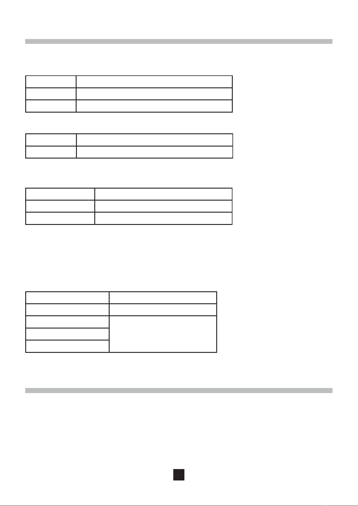
3. CHARACTERISTICS ...................................................................................................................10
.1 Characteristics o construction ........................................................................................10
. Electrical characteristics ................................................................................................... 10
. Environmental conditions..................................................................................................10
.4 Compliance with international standards .........................................................................10
4. MAINTENANCE ............................................................................................................................10
5. REPAIR .........................................................................................................................................11
6. WARRANTy ..................................................................................................................................11
7. TO ORDER ....................................................................................................................................11
Thank you or purchasing a mains adapter. To obtain the best service rom your unit:
read these operating instructions careully,
comply with the precautions or use.
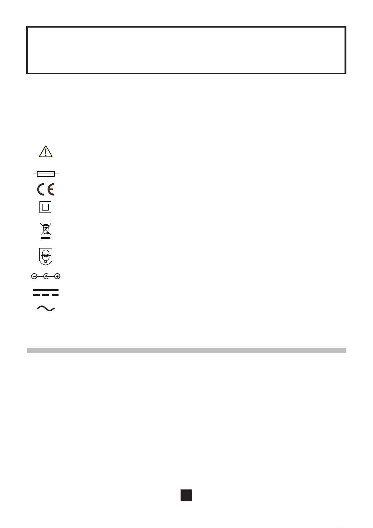
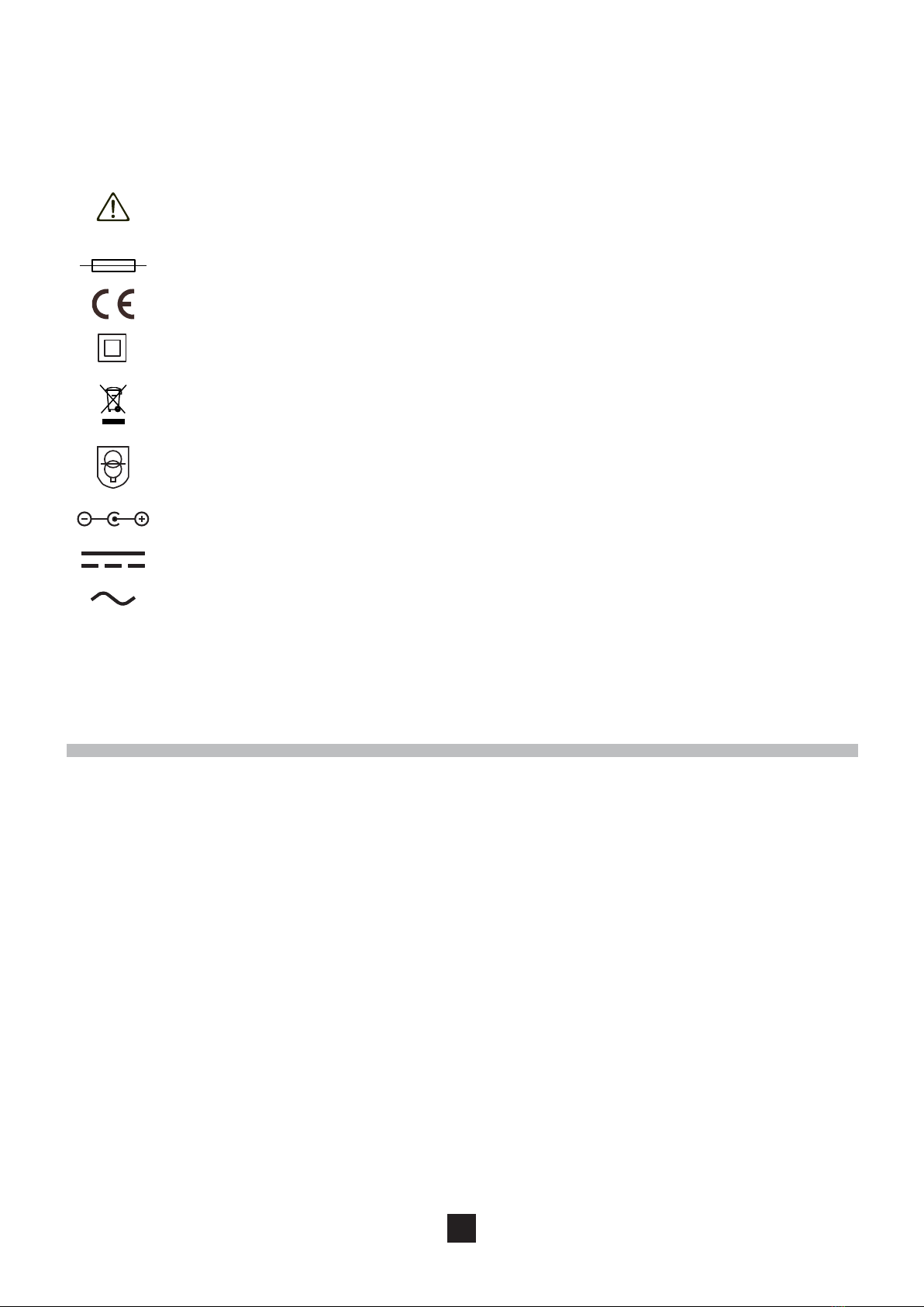
Meaning o symbols used on the device
Risk o danger. The operator must reer to these instructions whenever this danger
symbol appears.
Thermal use.
The CE marking guarantees conormity with European directives.
The device is protected throughout by double or reinorced insulation.
Selective sorting o waste or the recycling o electric and electronic material in the
European Union. In compliance with Directive WEEE 2002/96/EC, this material must not
be treated as household waste.
Saety transormer o circuits resistant to short-circuits.
Polarity o power connector as direct current.
Direct current.
Alternating current.
θ130°C

Outer side Inner side
1
2
1. PRESENTATION
The mains adapter is an accessory that is used to supply your sensor or probe rom a mains plug.
It consists o a mains unit, a connection cable and a semi-housing. This accessory is designed or use
on K housings.
Figure: the outer and inner sides o the adapter housing:
2. USE
To install the adapter, proceed as ollows:
Step 1:
Make sure that your device is not connected to an installation or measurement device.
Step 2: Remove the housing.
1. Use a screwdriver to unscrew the two screws at the back o the housing.
2. Open the housing.
3. Remove the battery.
Step 3: Install the adapter.
1. Connect the 9 V battery connector to the terminals inside the adapter housing (see above fgure, re.2).
2. Set the switch to OFF.
3. Close the housing and screw both screws back in.
4. Select the label in accordance with your model and afx the label to the ront o the housing
(see above fgure, re.1).

10
3. CHARACTERISTICS
3.1 CHARACTERISTICS OF CONSTRUCTION
Housing black plastic rigid shell
Dimension 103 x 64 x 28 mm
Mass approx. 200 g
3.2 ELECTRICAL CHARACTERISTICS
Input 230 V AC / 50 Hz / 30 mA AC / 6.9 V A
Output 9 V DC / 150 mA DC / 1.35 W
3.3 ENvIRONMENTAL CONDITIONS
The adapter must be used in the ollowing conditions:
Use indoors
Level o pollution 2
Altitude < 2000 m
3.4 COMPLIANCE WITH INTERNATIONAL STANDARDS
This instrument complies with the saety standard IEC 61010-1 (Ed. 2 o 2001) or 300 V installations in
category II on the mains supply side and up to 600 V in category III on the measurement device side.
Note:
The installation o the mains adapter does not change the standardised saety characteristics indicated
or the measurement device only. Below are the characteristics o the electrical housings:
Type o device Standardised characteristics
Series K 300 V CAT II
Series MA100
600 V CAT III
Series MA200
Series AmpFLEX A100
4. MAINTENANCE
To clean the mains adapter, proceed as ollows:
Disconnect everything connected to the device and set the switch to OFF.
Use a sot cloth, dampened with soapy water. Rinse with a damp cloth and dry rapidly with a dry cloth
or orced air.

11
5. REPAIR
For all repairs beore or ater expiry o warranty, please return the device to your distributor.
6. WARRANTy
Except as otherwise stated, our warranty is valid or twelve months starting rom the date on which the
equipment was sold. Extract rom our General Conditions o Sale provided on request.
The warranty does not apply in the ollowing cases:
inappropriate use o the equipment or use with incompatible equipment;
modifcations made to the equipment without the explicit permission o the manuacturer’s
technical sta;
work done on the device by a person not approved by the manuacturer;
adaptation to a particular application not anticipated in the defnition o the equipment or not
indicated in the user’s manual;
damage caused by shocks, alls or oods.
7. TO ORDER
The mains adapter is delivered in a cardboard box with:
a set o labels
the instruction sheet
Mains adapter Codes
Series K P01101966
Series MA100 P01102086
Series MA200 P01102087
Series AmpFLEX A100 P01101968

1
DEUTSCH
SICHERHEITSHINWEISE
Die Nichteinhaltung der im Folgenden beschriebenen Sicherheitsvorschriten kann die Risiken
ausgetauscht werden.
Respektieren Sie die Umweltbestimmungen bei der Nutzung.
MESSKATEGORIEN
Defnition der Messkategorien:
Die Messkategorie I bezieht sich au Messungen an Kreisen, die nicht direkt mit dem Stromnetz
verbunden sind.
an Niederspannungsinstallationen angeschlossen sind.
werden.
Die Messkategorie IV bezieht sich au Messungen, die an der Quelle von Niederspannungsinstallationen

1
INHALTSvERZEICHNIS
1. PR SENTATION ...........................................................................................................................14
2. vERWENDUNG ............................................................................................................................14
3. SPEZIFIKATIONEN .....................................................................................................................15
.1 Allgemeine Baudaten ........................................................................................................15
. Elektrische Spezifkationen ..............................................................................................15
. Umweltbedingungen .........................................................................................................15
..........................................................................15
4. PFLEGE ........................................................................................................................................15
5. REPARATUR .................................................................................................................................16
6. GARANTIE, SERvICE ..................................................................................................................16
7. BESTELLANGABEN .....................................................................................................................16
Sie haben ein
Lesen Sie aumerksam diese Bedienungsanleitung,
Beachten Sie genau die Benutzungshinweise.
Geahrenrisiko. Sobald dieses Geahrenzeichen autritt, ist der Bediener verpichtet, die
Anleitung zu Rate zu ziehen.
Thermische Sicherung.
Gleichstrom.
Wechselstrom.
θ130°C

14
Außenseite Innenseite
1
2
1. PR SENTATION
2. vERWENDUNG
Zur Montage des Adapters gehen Sie wie olgt vor:
Etappe 1:
ist.
3. Die Batterie enternen.
Etappe 3: Montage des Adapters.
Markierung 2) verbinden
2. Den Funktionsdrehschalter au OFF stellen
(Abbildung unten, Markierung 1).

15
3. SPEZIFIKATIONEN
3.1 ALLGEMEINE BAUDATEN
harte Schale aus schwarzem Plastik
Abmessungen 103 x 64 x 28 mm
Gewicht ca. 200 g
3.2 ELEKTRISCHE SPEZIFIKATIONEN
Eingang 230 V AC / 50 Hz / 30 mA AC / 6,9 V A
Ausgang 9 V DC / 150 mA DC / 1,35 W
3.3 UMWELTBEDINGUNGEN
Der Adapter muss unter den olgenden Bedingungen verwendet werden:
Verwendung
Verschmutzungsgrad 2
< 2000 m
3.4 KONFORMIT T MIT INTERNATIONALEN NORMEN
V in der
Kategorie II au der Netzanschlussseite und bis zu 600
Anmerkung:
Normspezifkationen
Serie K 300 V CAT II
Serie MA100
600 V CAT III
Serie MA200
Serie AmpFLEX A100
4. PFLEGE
Zum Reinigen des Netzadapters wie olgt vorgehen:
Mit einem leicht mit Seienwasser angeeuchteten Tuch reinigen. Mit einem euchten Lappen
abwischen und rasch mit einem trockenen Tuch oder in einem Lutstrom trocknen.

1
5. REPARATUR
6. GARANTIE, SERvICE
(Gesamttext au Anrage).
Herstellers;
-
dungszwecke;
7. BESTELLANGABEN
Der Netzadapter wird in einem Karton gelieert mit:
einem Satz Etiketten
der Bedienungsanleitung
Netzadapter Codes
Serie K P01101966
Serie MA100 P01102086
Serie MA200 P01102087
Serie AmpFLEX A100 P01101968

1
ITALIANO
ISTRUZIONI PER L’USO
elettrica, incendio, esplosione e distruzione dell’apparecchio e degli impianti.
Non utilizzare l’apparecchio in atmosera esplosiva o in presenza di gas o di umi infammabili.
Prima di ogni uso verifcare che gli isolanti di cavi, scatole e accessori siano in buono stato. Gli
elementi che presentino un isolante deteriorato (anche parzialmente) devono essere smontati per
riparazione o smaltimento.
Rispettare le condizioni ambientali d’uso.
Non modifcare l’apparecchio e non sostituirne i componenti con altri equivalenti. Le riparazioni o
le regolazioni devono essere eettuate da personale competente autorizzato.
CATEGORIE DI MISURA
Defnizione delle categorie di misura:
La categoria di misura I corrisponde alle misure eettuate su circuiti che non sono collegati
direttamente alla rete.
Esempio: circuiti elettronici protetti.
La categoria di misura II corrisponde alle misure eettuate sui circuiti che sono direttamente collegati
all’impianto a bassa tensione.
Esempio: alimentazione di elettrodomestici e attrezzi portatili.
La categoria di misura III corrisponde alle misure eettuate sull’impianto dell’edifcio.
Esempio: quadro di distribuzione, interruttori automatici, macchine o apparecchi industriali fssi.
La categoria di misura IV corrisponde alle misure eettuate alla onte dell’impianto a bassa
tensione.
Esempio: mandata di energia, contatori e dispositivi di protezione.

1
θ130°C
INDICE
1. PRESENTAZIONE ........................................................................................................................19
2. USO ...............................................................................................................................................19
3. CARATTERISTICHE ....................................................................................................................20
.1 Caratteristiche costruttive ................................................................................................. 0
. Caratteristiche elettriche ...................................................................................................0
. Condizioni ambientali ........................................................................................................0
................................................................................0
4. MANUTENZIONE .........................................................................................................................20
5. RIPARAZIONE ..............................................................................................................................21
6. SERvIZIO DI GARANZIA .............................................................................................................21
7. PER ORDINARE ...........................................................................................................................21
Ha acquistato un adattatore di rete. Vi ringraziamo per la fducia che ci avete accordato. Per ottenere
le migliori prestazioni dal vostro strumento:
Seguite attentamente le presenti istruzioni per l’uso.
Rispettate le precauzioni d’uso.
Signifcato dei simboli utilizzati sull’apparecchio
Pericolo. L’utilizzatore deve consultare il presente manuale ogni volta che incontra il
simbolo di pericolo.
Fusibile termico.
Apparecchio completamente protetto con doppio isolamento e isolamento rinorzato.
Selezione dei rifuti per il riciclo del materiale elettrico ed elettronico all’interno dell’Unione
essere smaltito come rifuto domestico.
Trasormatore di sicurezza dei circuiti resistenti al cortocircuito.
Corrente continua.
Corrente alternata.

1
Lato esterno Lato interno
1
2
1. PRESENTAZIONE
Figura: acciata interna ed esterna della scatola dell’adattatore:
2. USO
Per montare l’adattatore procedere come segue:
Fase 1:
Verifcare che l’apparecchio non sia connesso ad un impianto o ad uno strumento di misura.
Fase 2: Smontaggio della scatola.
1. Con un cacciavite svitare le due viti poste sul retro della scatola;
2. Aprire la scatola;
3. Togliere la pila.
Fase 3: Montaggio dell’adattatore.
1. Collegare il connettore della pila 9V ai morsetti posti all’interno della scatola dell’adattatore (fgura
in alto, ri. 2);
2. Posizionare il commutatore su OFF;
3. Richiudere la scatola e riavvitare le due viti;
4. Scegliere l’etichetta secondo il modello di cui si dispone ed incollarla sulla acciata anteriore della
scatola (fgura in alto, ri. 1).

0
3. CARATTERISTICHE
3.1 CARATTERISTICHE COSTRUTTIvE
Scatola scocca rigida in plastica nera
Dimensioni 103 x 64 x 28 mm
Peso 200 g circa
3.2 CARATTERISTICHE ELETTRICHE
Ingresso 230 V AC / 50 Hz / 30 mA AC / 6,9 V A
Uscita 9 V DC / 150 mA DC / 1,35 W
3.3 CONDIZIONI AMBIENTALI
L’adattatore deve essere utilizzato nelle seguenti condizioni:
Uso all’interno
Grado di inquinamento 2
Altitudine < 2000 m
3.4 CONFORMIT ALLE NORME INTERNAZIONALI
categoria II lato alimentazione di rete e fno a 600 V di categoria III lato strumento di misura.
Nota:
Il montaggio dell’adattatore di rete non modifca le caratteristiche normative di sicurezza indicate per
il solo strumento di misura. Caratteristiche delle centraline elettroniche:
Tipo di strumento Caratteristiche normative
Serie K 300 V CAT II
Serie MA100
600 V CAT III
Serie MA2100
Serie AmpFLEX A100
4. MANUTENZIONE
Per pulire l’adattatore di rete procedere come segue:
Scollegare tutte le connessioni dell’apparecchio e posizionare il commutatore su OFF;
Utilizzare un panno morbido leggermente imbevuto di acqua saponata. Risciacquare con un panno
umido ed asciugare subito con un panno asciutto o con un getto d’aria.
Other manuals for K Series
1
This manual suits for next models
3
Table of contents
Languages:
Other Chauvin Arnoux Adapter manuals
Popular Adapter manuals by other brands

Panasonic
Panasonic BLPA100KTA - HD-PLC ETHERNET ADAPT.2PK operating instructions

Hitachi
Hitachi HARC70-CE1 Installation and operation manual

Westermo
Westermo FD-10 installation manual

Belkin
Belkin F5U120-PC installation guide

US Robotics
US Robotics 5426 Quick installation guide

Segger
Segger J-Link user guide