manuals.online logo
Brands
  1. Home
  2. •
  3. Brands
  4. •
  5. CHD Elektroservis
  6. •
  7. Media Converter
  8. •
  9. CHD Elektroservis SH2-M User manual

CHD Elektroservis SH2-M User manual

7
Model 8-437
ver. 1.0 and 2.0
INSTALLATION MANUAL
©
2017 CHD Elektroservis
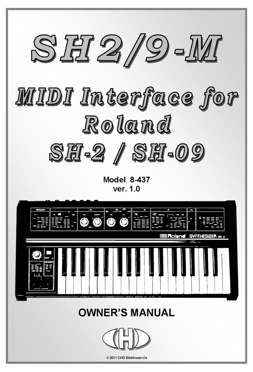
SH2/9-M
MIDI Interface for Roland SH-2 / SH-09
Model 8-437 ver. 1.0, 2.0
Copyright © 2017 CHD Elektroservis. All rights reserved.
No part of this publication may be reproduced in any form without the written permission of CHD Elektroservis.
2
Content
page
1. General information . . . . . . . . . . . . . . . . . . . . . . . . . . . . . . . . . . . 3
1.1. Parts of MIDI interface kit . . . . . . . . . . . . . . . . . . . . . . . . . . . . . . . . 3
2. MIDI interface installation . . . . . . . . . . . . . . . . . . . . . . . . . . . . . . . . 4
2.1. Instrument’s opening . . . . . . . . . . . . . . . . . . . . . . . . . . . . . . . . . . 5
2.2. Drilling of holes for MIDI sockets, switch and indication LED . . . . . . . . . . . . . . 5
2.3. Montage of MIDI sockets, switch and indication LED . . . . . . . . . . . . . . . . . . 6
2.4. Montage of power supply bunched cables . . . . . . . . . . . . . . . . . . . . . . . 7
2.5. Montage of signal bunched cables . . . . . . . . . . . . . . . . . . . . . . . . . . . 8
2.5.1. Bender panel . . . . . . . . . . . . . . . . . . . . . . . . . . . . . . . . . . . . . . 8
2.5.2. Jack connectors board . . . . . . . . . . . . . . . . . . . . . . . . . . . . . . . . . 9
2.5.3. Instrument’s boards . . . . . . . . . . . . . . . . . . . . . . . . . . . . . . . . . . . 10
2.6. Montage of interface’s board . . . . . . . . . . . . . . . . . . . . . . . . . . . . . . 12
2.7. Adjusting of interface . . . . . . . . . . . . . . . . . . . . . . . . . . . . . . . . . . 15
2.8. Finishing of installation . . . . . . . . . . . . . . . . . . . . . . . . . . . . . . . . . 16
3. Changes and new functions . . . . . . . . . . . . . . . . . . . . . . . . . . . . . . . 18
4. Limitation during instrument usage . . . . . . . . . . . . . . . . . . . . . . . . . . . 18
5. Tips for installation . . . . . . . . . . . . . . . . . . . . . . . . . . . . . . . . . . . 18
This manual in PDF form is available on supplemental CD-ROM or on manufacturer’s web-pages.
Manufacturer :
CHD Elektroservis
Nad kundratkou 27, 19000 Praha 9
Czech Republic
info@chd-el.cz
www.chd-el.cz
SH2/9-M
MIDI Interface for Roland SH-2 / SH-09
Model 8-437 ver. 1.0, 2.0
Copyright © 2017 CHD Elektroservis. All rights reserved.
No part of this publication may be reproduced in any form without the written permission of CHD Elektroservis.
3
1. GENERAL INFORM ATION
SH2/9-M MIDI interface allows full integration of Roland SH-2 and SH-09 instruments to MIDI
system. Interface affects some instrument’s circuits (BENDER, VCO, VCF, VCA a ENV) which can be
controlled via MIDI commands with help of the interface. However, all original features of SH-2 / SH-09
instrument stay unchanged after the interface installation and the instrument can be used by the same
way. Simplified block functional schematic of the instrument after the interface installation shows pic.
1.1.
Pic. 1.1 – Connection to instrument
Construction of SH2/9-M MIDI interface is a little bit different for SH-2 and SH-09 instrument.
Therefore check before the installation whether you have the right version of the interface. Version can
be checked on identification label on interface board (see pic. 1.2).
In course of time, software of the interface can be revised. Actual version of software be to detect
on identification label on interface’s processor (see pic. 1.2).
Pic. 1.2 – Identification of instrument model and SW version
1.1. PARTS OF MIDI INTERFACE KIT
Delivery of MIDI interface kit contents all parts necessary for installation inc. all support and
coupling elements. Parts of delivery are also manuals for installation, handling and interface’s SysEx
communication and CD-ROM with support software. Please check if the delivery is complete before
installation (see pic. 1.1.1).
SH2/9-M
MIDI Interface for Roland SH-2 / SH-09
Model 8-437 ver. 1.0, 2.0
Copyright © 2017 CHD Elektroservis. All rights reserved.
No part of this publication may be reproduced in any form without the written permission of CHD Elektroservis.
4
Pic. 1.1.1 – Parts of interface kit
The SH2/9-M interface kit delivery contents :
1. MIDI Interface board
2. 2x DIN-5 socket with cable
3. Bunched cables with tumbler switch and LED
4. Power supply bunched cable (4-wire)
5. Signal bunched cables (10-wire)
6. Coupling elements (screws, nuts, washers, LED holder, tightening strips, insulation tubes …)
7. CD-ROM with support software and manuals in PDF form
8. 3x manual in printed form
2. MIDI INTERFACE INSTALLATION
Mounting of the interface in the Roland SH-2 / SH-09 synthesizer is very easy. If you follow the
instructions from this manual, there should be no major problems during the installation. The interface
installation procedure is thoroughly described in the following chapters. Please follow these
instructions accurately to avoid any damage of the instrument.
Attention! Disconnect the instrument form the mains prior to the installation. There is
a risk of the electric shock!
Attention! Observe precautions for handling electrostatic discharge sensitive devices!
The producer is not responsible for any eventual mechanical or electrical damage of
the SH-2 / SH-09 instrument caused by the infringement of the described installation
procedure or by careless manipulation during the installation of the MIDI interface!
It is recommended to calibrate the SH-2 / SH-09 accordingly to the instructions in
service manual of the instrument prior the interface installation. This ensures trouble-
free operation of the interface.
SH2/9-M
MIDI Interface for Roland SH-2 / SH-09
Model 8-437 ver. 1.0, 2.0
Copyright © 2017 CHD Elektroservis. All rights reserved.
No part of this publication may be reproduced in any form without the written permission of CHD Elektroservis.
5
Most of installation procedures is common for both SH-2 and SH-09 models of the instrument.
Some differences are only in connection of signal bunched cables (chapter 2.5). Pass along
instructions for given model of the instrument during installation of these bunched cables!
2.1. OPENING OF THE INSTRUMENT
a) Unscrew six screws on top panel of the instrument (pic. 2.1.1) and three screws on rear panel
of the instrument (pic. 2.1.2). Keep the screws. They will be used again after the MIDI kit installation.
b) Carefully open the instrument - lift off the instrument’s panel. Now, all instrument’s parts and
boards needed for the interface installation are accessible see pic. 2.1.3.
Pic. 2.1.1 Pic. 2.1.2
Pic. 2.1.3
2.2. DRILLING OF HOLES FOR MIDI SOCKETS, SWITCH AND INDICATION LED
The interface has both MIDI input and output. Only MIDI input is implicitly necessary for the
interface working. MIDI output need not to be installed – see chapter 5. Of course, usage of both MIDI
input and output (MIDI-IN and MIDI-THRU/OUT sockets) is more convenient for easy interconnection
of parts of whole MIDI system.
There are two elements for the interface control - tumbler switch and two-color LED. They are not
necessary implicitly for the interface working. They need not to be installed – see chapter 5. Of course,
usage of them is more convenient for easier device control.
SH2/9-M
MIDI Interface for Roland SH-2 / SH-09
Model 8-437 ver. 1.0, 2.0
Copyright © 2017 CHD Elektroservis. All rights reserved.
No part of this publication may be reproduced in any form without the written permission of CHD Elektroservis.
6
Suitable place for MIDI sockets and control elements is on left side plate of the instrument (see
pic. 2.2.1). It is necessary to drill holes for them to the side plate.
a) Left side plate is fixed to bottom of the instrument with five screws (pic. 2.2.2). These screws
must be unscrewed and then it is possible remove the side plate.
Pic. 2.2.1 Pic. 2.2.2
b) Drill two holes with diameter 16 mm and four holes with diameter 3,5 mm (from side wall) – see
pic. 2.2.3. Use sharp drills and work carefully so that side plate was not damaged during drilling!
c) Drill one hole with diameter 6,5 mm and one hole with diameter 6 mm on top of the side plate -
see pic. 2.2.4. Work carefully again so that side plate was not damaged!
Pic. 2.2.3 Pic. 2.2.4
d) Clean the edge of all holes with small rasp or with point of bigger drill after drilling.
2.3. MONTAGE OF MIDI SOCKETS, SWITCH AND INDICATION LED
Pic. 2.3.1 Pic. 2.3.2
SH2/9-M
MIDI Interface for Roland SH-2 / SH-09
Model 8-437 ver. 1.0, 2.0
Copyright © 2017 CHD Elektroservis. All rights reserved.
No part of this publication may be reproduced in any form without the written permission of CHD Elektroservis.
7
a) Insert LED holder into 6,5 mm hole on top of the side plate. Plant lock ring of LED holder to
two-color LED on power supply bunched cables. Then insert two-color LED into holder and fix it by
overthrust of the ring on the holder (pic. 2.3.1).
b) Insert tumbler switch into the other hole on top of the side plate so that its not connected lead
was near to LED. Fix the switch to the side plate with help of nuts and washers (pic. 2.3.2).
c) Get flat connectors of MIDI cables through the holes in side wall of the side plate and insert
DIN sockets of the cables into the holes fully (pic. 2.3.3). Both cables are identical and they can be
swapped.
d) Fix DIN sockets to the side plate using screws, nuts and washers (pic. 2.3.4).
Pic. 2.3.3 Pic. 2.3.4
e) Insert side plate with installed MIDI sockets, switch and LED back to the instrument’s bottom
so that newly installed bunched cables are coming out at rear panel of the instrument (pic. 2.3.5).
Pic. 2.3.5
f) Fix the side plate back to bottom of the instrument with help of five screws (see pic 2.2.2).
g) It is suitable to label the DIN sockets ("MIDI IN", "M IDI THRU/OUT") – for example, with self-
adhesive foil glued near to the sockets on side plate of the instrument.
2.4. MONTAGE OF POWER SUPPLY BUNCHED CABLES
Pic. 2.4.1
Power supply bunched cables are
equipped with flat 4-pin connector on one
end (pic. 2.4.1). All wires outgoing from this
connector must be connected to
instrument’s power supply board as
displayed on pic. 2.4.2.
SH2/9-M
MIDI Interface for Roland SH-2 / SH-09
Model 8-437 ver. 1.0, 2.0
Copyright © 2017 CHD Elektroservis. All rights reserved.
No part of this publication may be reproduced in any form without the written permission of CHD Elektroservis.
8
Pic. 2.4.2
a) Solder the red wire Nr. 1 (+15V) to stabilized supply voltage +15V – to one of solder lugs
marked with “+15“ symbol, on the right on power supply board (pic. 2.4.2).
b) Solder the blue wire Nr. 2 (-15V) to stabilized supply voltage -15V – to one of solder lugs
marked with “-15“ symbol , on the right on power supply board (pic. 2.4.2).
c) Solder the black wire Nr. 3 (GND) to ground potential – to one of solder lugs marked with
“GND” symbol, , on the right on power supply board (pic. 2.4.2).
d) Solder the yellow wire Nr. 4 (+20V) to supply voltage +20V. Most suitable point is positive pole
terminal of electrolytic capacitor C45 on power supply board (pic. 2.4.2).
2.5. MONTAGE OF SIGNAL BUNCHED CABLES
Signal bunched cables are equipped with flat 10-pin connector on one end. Wires outgoing from
this connector must be connected to several places of the instrument (pic. 2.5).
Pic. 2.5
2.5.1. BENDER PANEL
a) Wires Nr. 1 and 2 of signal bunched cables will be connected to bender board (on the left of
the instrument’s keyboard). It is necessary do disassemble this board. Block of bender is fixed to
instrument’s bottom with four screws – they must be unscrewed (pic. 2.5.1.1).
b) After that, it is possible to lift off the bender panel (pic. 2.5.1.2).
SH2/9-M
MIDI Interface for Roland SH-2 / SH-09
Model 8-437 ver. 1.0, 2.0
Copyright © 2017 CHD Elektroservis. All rights reserved.
No part of this publication may be reproduced in any form without the written permission of CHD Elektroservis.
9
Pic. 2.5.1.1 Pic. 2.5.1.2
c) Unsolder yellow wire interconnecting sliding contact of bender potentiometer and solder pad
“2“ on bender board (pic. 2.5.1.3).
d) Solder the green wire Nr. 1 (BEND-IN) of signal bunched cables to sliding contact of bender
potentiometer (pic. 2.5.1.4).
e) Solder the yellow wire Nr. 2 (BEND-OUT) of signal bunched cables to solder pad “2“ on bender
board (pic. 2.5.1.4).
Pic. 2.5.1.3 Pic. 2.5.1.4
f) Place block of bender back to its original position and fix it to instrument’s bottom with four
screws (see pic. 2.5.1.1).
2.5.2. JACK CONNECTORS BOARD
Pic. 2.5.2.1 Pic. 2.5.2.2
SH2/9-M
MIDI Interface for Roland SH-2 / SH-09
Model 8-437 ver. 1.0, 2.0
Copyright © 2017 CHD Elektroservis. All rights reserved.
No part of this publication may be reproduced in any form without the written permission of CHD Elektroservis.
10
a) Wires Nr. 3, 4, 9 and 10 of signal bunched cables will be connected to Jack connectors board
on rear panel of top part of the instrument (pic. 2.5.2.1).
b) Unsolder white wire marked with “9” symbol from board of Jack connectors (pic. 2.5.2.2). The
wire is used to be glued on the board so it is necessary to unfasten it first.
c) Place a heat-shrink insulation tube φ 2 mm on green cable Nr. 3 (KBD-IN) of signal bunched
cables. Solder this wire to freed white wire coming originally to Jack connector board (pic. 2.5.2.3).
d) Isolate the connection with the insulation tube and heat it (with a hot-flue pistol for example)
until it shrinks tightly to the cables (pic. 2.5.2.4).
Pic. 2.5.2.3 Pic. 2.5.2.4
e) Solder the yellow wire Nr. 4 (KBD-OUT) of signal bunched cables to freed solder pad (9) on
board of Jack connectors (pic. 2.5.2.5).
f) Solder the black wire Nr. 9 (GND) of signal bunched cables to ground potential – to solder pad
(2) on board of Jack connectors (pic. 2.5.2.6).
g) Solder the red wire Nr. 10 (GATE) of signal bunched cables to solder pad (8) on board of Jack
connectors (pic. 2.5.2.6).
Pic. 2.5.2.5 Pic. 2.5.2.6
2.5.3. INSTRUMENT’S BOARDS
a) Wires Nr. 5 to 8 of signal bunched cables (they control VCF and VCA) will be connected to flat
cables which interconnect boards of the instrument. At tention – places of connection are different
for SH-2 and SH-09 instruments! In SH-2 instrument, used board has denotation 052H177A. It is
upper right (visible) board of block of the instrument’s panel (pic. 2.5.3.1). In SH-09 instrument, used
board has denotation 052H141. It is only one upper (visible) board of block of the instrument’s panel
(pic. 2.5.3.2).
SH2/9-M
MIDI Interface for Roland SH-2 / SH-09
Model 8-437 ver. 1.0, 2.0
Copyright © 2017 CHD Elektroservis. All rights reserved.
No part of this publication may be reproduced in any form without the written permission of CHD Elektroservis.
11
Pic. 2.5.3.1 - SH-2
Pic. 2.5.3.2 - SH-09
b) Method of montage is the same for both models of the instrument but placing of flat cables with
signals for VCF and VCA control is different for SH-2 and SH-09 instruments!
- in SH-2 instrument, wires Nr. 7 for VCA and Nr. 12 for VCF of flat cables will be used (pic. 2.5.3.3),
- in SH-09 instrument, wires Nr. 30 for VCA and Nr. 31 for VCF of flat cables will be used (pic. 2.5.3.4).
Wires of flat cables are numbered stepwise from the left from board margin.
Pic. 2.5.3.3 – SH-2 Pic. 2.5.3.4 – SH-09
Pic. 2.5.3.5 Pic. 2.5.3.6
SH2/9-M
MIDI Interface for Roland SH-2 / SH-09
Model 8-437 ver. 1.0, 2.0
Copyright © 2017 CHD Elektroservis. All rights reserved.
No part of this publication may be reproduced in any form without the written permission of CHD Elektroservis.
12
c) Incise insulating material of flat cables with sharp knife and detach necessary wires see
previous item (pic. 2.5.3.5).
d) Cut off (interrupt) these wires. Then carefully strip them for about ca 5 mm (insulating material
is fairly relatively adamant) and tin plate ends of the wires (pic. 2.5.3.6).
e) Adapt length of wires Nr. 5 to 8 of interface’s signal bunched cables as necessary and place
heat-shrink insulation tubes φ 4 mm on these wires. Then the wires solder to freed ends of wires of
instrument’s flat cables (pic. 2.5.3.7):
In SH-2 instrument:
- solder the green wire Nr. 5 (VCF-IN) of signal bunched cables to end of wire Nr. 12 of flat cable
outgoing from bottom instrument’s board (i.e. the board near to instrument’s panel),
- solder the yellow wire Nr. 6 (VCF-OUT) of signal bunched cables to end of wire Nr. 12 of flat cable
outgoing from upper instrument’s board (i.e. the visible board),
- solder the green wire Nr. 7 (VCA-IN) of signal bunched cables to end of wire Nr. 7 of flat cable
outgoing from bottom instrument’s board (i.e. the board near to instrument’s panel),
- solder the yellow wire Nr. 8 (VCA-OUT) of signal bunched cables to end of wire Nr. 7 of flat cable
outgoing from upper instrument’s board (i.e. the visible board),
In SH-09 instrument:
- solder the green wire Nr. 5 (VCF-IN) of signal bunched cables to end of wire Nr. 31 of flat cable
outgoing from bottom instrument’s board (i.e. the board near to instrument’s panel),
- solder the yellow wire Nr. 6 (VCF-OUT) of signal bunched cables to end of wire Nr. 31 of flat cable
outgoing from upper instrument’s board (i.e. the visible board),
- solder the green wire Nr. 7 (VCA-IN) of signal bunched cables to end of wire Nr. 30 of flat cable
outgoing from bottom instrument’s board (i.e. the board near to instrument’s panel),
- solder the yellow wire Nr. 8 (VCA-OUT) of signal bunched cables to end of wire Nr. 30 of flat cable
outgoing from upper instrument’s board (i.e. the visible board),
f) Isolate the connections with the insulation tubes and heat them (with a hot-flue pistol for
example) until they shrink tightly to the cables (pic. 2.5.3.8).
Pic. 2.5.3.7 Pic. 2.5.3.8
2.6. MONTAGE OF INTERFACE’S BOARD
Interface board will be placed on bottom plate of the instrument between transformer and power
supply board (pic. 2.6.1). So that there will be place for interface board, it is necessary to shift original
bunched cables fixed to instrument’s bottom plate.
SH2/9-M
MIDI Interface for Roland SH-2 / SH-09
Model 8-437 ver. 1.0, 2.0
Copyright © 2017 CHD Elektroservis. All rights reserved.
No part of this publication may be reproduced in any form without the written permission of CHD Elektroservis.
13
Pic. 2.6.1
a) Cut off tightening plastic strips and unfasten original bunched cables.
b) Unscrew plastic fixing lugs from bottom of the instrument and relocate them to another
opportune holes.
c) Now fix all bunched cables (including newly installed) back to fixing lugs with help of new
tightening plastic strips (pic. 2.6.2).
Pic. 2.6.2
e) Remove protective foil form the self-adhesive supports of interface’s board (pic. 2.6.3).
f) Put interface’s board to bottom of the instrument so that connectors X1 to X4 are pointed at
rear panel of the instrument (pic. 2.6.4) and then fix the self-adhesive supports by pressing down.
SH2/9-M
MIDI Interface for Roland SH-2 / SH-09
Model 8-437 ver. 1.0, 2.0
Copyright © 2017 CHD Elektroservis. All rights reserved.
No part of this publication may be reproduced in any form without the written permission of CHD Elektroservis.
14
Pic. 2.6.3 Pic. 2.6.4
g) Plug the 10-pin connector of signal bunched cables to X4 head on the left on the interface’s
board. Orientation of the connector is unambiguously given by the connector lock and it can’t be
plugged to the contrary (pic. 2.6.5).
h) Plug the 4-pin connector of bunched cables with switch and LED to X3 on the interface’s
board. Orientation of the connector is unambiguously given by the connector lock again (pic. 2.6.5).
i) Plug two 3-pin connectors of MIDI cables to X1 a X2 heads on the right on the interface’s
board. Orientation of the connectors is given by the connector lock again but be sure that the
connectors are not exchanged. MIDI input must be put to X1 head and MIDI output to X2 head (see
pic. 2.6.5).
j) Plug the 4-pin connector of power supply bunched cables to X5 head on the right on bottom
edge of the interface’s board. Orientation of the connector is unambiguously given by the connector
lock again (pic. 2.6.5).
Pic. 2.6.5
SH2/9-M
MIDI Interface for Roland SH-2 / SH-09
Model 8-437 ver. 1.0, 2.0
Copyright © 2017 CHD Elektroservis. All rights reserved.
No part of this publication may be reproduced in any form without the written permission of CHD Elektroservis.
15
2.7. ADJUSTMENT OF INTERFACE
It is necessary to adjust the interface after mechanical installation. It will be done with help of two
trimmers (BEND and TUNE) and jumper on the interface’s board (see pic. 2.7.1). Adjusting procedure
is following:
Pic. 2.7.1
a) Plug jumper to two-pin jumper head on interface’s board (see pic. 2.7.1).
b) Connect audio output of the instrument to amplifier or combo etc.
c) Set some of controllers on instrument’s panel to these positions:
For SH-2instrument:
• VCO (common) Æ MOD = 0, AUTO BEND = 0
• VCO-1 Æ RANGE = 8‘, WAVEFORM = Saw, BENDER = On
• AUDIO MIXER Æ VCO-1 SUB = 0, VCO-1 = 10, VCO-2 = 0
• VCF Æ CUTOFF FREQ = 10, RESONANCE = 0, ENV = UP/10, MOD = 0, KYBD = 0
• VCA Æ HOLD
• ENV Æ GATE, A = 0, D = 0, S = 10, R = 0
• PORTAMENTO = 0
• BENDER Æ VCO = 0, VCF = 0
For SH-09 instrument:
• VCOÆ MOD = 0, RANGE = 8, WAVEFORM = Saw
• AUDIO MIXER Æ VCO = 10, SUB OSC = 0, EXT = 0
• VCF Æ CUTOFF FREQ = 10, RESONANCE = 0, ENV = UP/10, MOD = 0
• VCA Æ HOLD
• ENV Æ GATE, A = 0, D = 0, S = 10, R = 0
• PORTAMENTO = 0
• BENDER Æ VCO = 0, VCF = 0
Positions of other controllers on instrument’s panel are not significant.
d) Plug instrument’s power supply cable to mains socket and switch on the instrument by main
switch POWER. Attention – work very carefully during whole adjusting procedure - there is a
risk of the electric shock!
e) Turn interface’s switch (newly installed on instrument’s side plate) to OFF position – indication
LED of the interface lights in red. Press key C2 on instrument’s keyboard (pic. 2.7.2). Now tone with
frequency ca 261,63 Hz is heard – this corresponds to VCO‘s control voltage +3V. Frequency and
control voltage depend on setting of TOTAL TUNE on panel of SH-2 instrument or TUNE on SH-09
instrument respectively.
SH2/9-M
MIDI Interface for Roland SH-2 / SH-09
Model 8-437 ver. 1.0, 2.0
Copyright © 2017 CHD Elektroservis. All rights reserved.
No part of this publication may be reproduced in any form without the written permission of CHD Elektroservis.
16
Pic. 2.7.2
f) Turn interface’s tumbler switch to ON position (indication LED of the interface lights in green).
By circumvolution of TUNE trimmer on the interface’s board, find position where the same tone sounds
as in previous item. It can be determined with help of tuner or by ear also.
g) Repeat items e) and f) as long as the same tone is heard in both positions of the switch. After
final adjusting of TUNE trimmer, turn interface’s tumbler switch to OFF position (indication LED of the
interface lights in red) and press key C2 on instrument’s keyboard again (see pic. 2.7.2).
h) Move BENDER-VCO slider on instrument’s panel between terminal positions (from “0“ position
to “10“ position and back) and, by circumvolution of BEND trimmer on the interface’s board, find
position where the same tone sounds in both “0” and “10” positions of the slider. It can be determined
with help of tuner or by ear also. Attention - BENDER controller (lever) on instrument’s panel must be
in quiescent (middle) position during whole adjusting procedure!
i) After final adjusting of BEND trimmer, switch the instrument off by main switch POWER and
disconnect power supply cable from mains socket.
j) Remove jumper from jumper head on interface’s board.
2.8. FINISHING OF INSTALLATION
Turn over the top panel of the instrument (close the instrument) and fix it with six screws to side
plates and with three screws to bottom part of the instrument. This is the reverse procedure of that
described in the chapter 2.1.
Pic. 2.8.1 Pic. 2.8.2
Installation of the MIDI interface kit is finished and the instrument is prepared for communication
via MIDI bus (pic. 2.8.3).
Please read carefully user manual of the interface before usage of modified instrument.
SH2/9-M
MIDI Interface for Roland SH-2 / SH-09
Model 8-437 ver. 1.0, 2.0
Copyright © 2017 CHD Elektroservis. All rights reserved.
No part of this publication may be reproduced in any form without the written permission of CHD Elektroservis.
17
Pic. 2.8.3a – Installation in SH-2 instrument:
Pic. 2.8.3b – Installation in SH-09 instrument:
SH2/9-M
MIDI Interface for Roland SH-2 / SH-09
Model 8-437 ver. 1.0, 2.0
Copyright © 2017 CHD Elektroservis. All rights reserved.
No part of this publication may be reproduced in any form without the written permission of CHD Elektroservis.
18
3. CHANGES AND NEW FUNCTIONS
If the interface is switched off and if it isn’t connected to M IDI system, Roland SH-2 / SH-09
instruments works exactly the same way as before the interface installation.
After the interface activation, it controls BENDER, VCO, VCF, VCA and ENV circuits of the
instrument via MIDI commands. More over, the interface includes internal software LFO which can be
used as next source for modulation of VCO.
Enhanced function for control of the instrument via MIDI communication are described in detail in
user manual of the interface.
4. LIMITATION DURING INSTRUMENT USAGE
When the interface is active, it is impossible to use own instrument’s keyboard. If a key on
instrument’s keyboard is pressed, instrument’s VCO will not be affected (detuned) but unadvisable
launching of envelope generator will occur.
Also portamento circuit (PORTAMENTO slider) of the instrument is totally functionless after the
interface activation! Unfortunately, instrument’s hardware design don’t allow usage of portamento if
instrument’s VCO is controlled by external voltage.
Function of BENDER controller on instrument’s panel depends on CONTROL - Bender Mode
parameter setting (see user manual of the interface):
• In “Instrument“ mode, manual controller BENDER on instrument’s panel stay fully functional and it
can be used by standard way.
• In “MIDI“ mode, manual controller BENDER is disconnected and it is substituted by D/A converter of
the interface. Then MIDI command Pitch Bend (Pitch Wheel) takes control over BENDER function.
All other control elements on SH-2 / SH-09 instrument’s panel stay fully functional although the
instrument is driven via MIDI bus with help of SH2/9-M interface. If the instrument is controlled via
MIDI, we recommend to disuse GATE+TRIG position of selector for choice of envelope generator
(ENV) launching. In this mode, unwanted triggering of envelope can occur. It is caused by influence of
frequency jumping if VCO is modulated by interface’s internal software LFO.
5. TIPS FOR INSTALLATION
a) Output MIDI – THRU/OUT
Interface SH2/9-M has both MIDI input and output. However, only MIDI input is unconditionally
necessary for basic work of the interface (i.e driving the instrument via MIDI commands). MIDI
THRU/OUT output connector need not to be installed at all if if you don’t require transfer of MIDI data
to another MIDI devices (THRU function ) or reverse communication of the interface with host system
(OUT function). It that case, connector X2 on interface board will stay unconnected (see pic. 2.6.5).
b) Switch and indication LED
Also installation of bunched cables of switch and indication LED isn’t unconditional. You need not
to install this bunched cables if you don’t want to infringe excessively to instrument’s panel by drilling.
however, jumper must be plugged on pins Nr. 1 and 2 of X3 connector in that case (see pic. 5.1).
SH2/9-M
MIDI Interface for Roland SH-2 / SH-09
Model 8-437 ver. 1.0, 2.0
Copyright © 2017 CHD Elektroservis. All rights reserved.
No part of this publication may be reproduced in any form without the written permission of CHD Elektroservis.
19
Pic. 5.1
Also it is possible to install only indication LED on instrument’s panel. In that case, remove (cut-
off) switch from bunched cables and connect (solder) together two black and one yellow wires lead to
the switch originally and insulate connection of the wires (see pic. 5.2).
Pic. 5.2
Then the interface works this way: Immediately after its switching on, the interface is activated but
it still doesn’t affect the instrument – the instrument can be used like original one without installed
interface. As lately as first MIDI command is coming to interface’s MIDI input, the interface takes
control over keyboard and other instrument’s circuits. So that own instrument’s keyboard can be used
again, the interface must be reset. It can be done by turning of and on the instrument or with help of
MIDI command “HW Reset” sent to the interface (see user manual of the interface).
7

This manual suits for next models

2

Other CHD Elektroservis Media Converter manuals

CHD Elektroservis 8-443 User manual

CHD Elektroservis

CHD Elektroservis 8-443 User manual

CHD Elektroservis K770-KBD User manual

CHD Elektroservis

CHD Elektroservis K770-KBD User manual

CHD Elektroservis JP4-KBD User manual

CHD Elektroservis

CHD Elektroservis JP4-KBD User manual

CHD Elektroservis SY2-KBD User manual

CHD Elektroservis

CHD Elektroservis SY2-KBD User manual

CHD Elektroservis K770-KBD User manual

CHD Elektroservis

CHD Elektroservis K770-KBD User manual

CHD Elektroservis CRX8-M User manual

CHD Elektroservis

CHD Elektroservis CRX8-M User manual

CHD Elektroservis KM500-KBD User manual

CHD Elektroservis

CHD Elektroservis KM500-KBD User manual

CHD Elektroservis SH101-M User manual

CHD Elektroservis

CHD Elektroservis SH101-M User manual

CHD Elektroservis MXC-56 User manual

CHD Elektroservis

CHD Elektroservis MXC-56 User manual

CHD Elektroservis VS-MIDI 8-434 User manual

CHD Elektroservis

CHD Elektroservis VS-MIDI 8-434 User manual

CHD Elektroservis SH2/9-M User manual

CHD Elektroservis

CHD Elektroservis SH2/9-M User manual

CHD Elektroservis 8-440 User manual

CHD Elektroservis

CHD Elektroservis 8-440 User manual

CHD Elektroservis K770-KBD User manual

CHD Elektroservis

CHD Elektroservis K770-KBD User manual

CHD Elektroservis MXC-200 User manual

CHD Elektroservis

CHD Elektroservis MXC-200 User manual

CHD Elektroservis P6-KBD User manual

CHD Elektroservis

CHD Elektroservis P6-KBD User manual

CHD Elektroservis P61-KBD User manual

CHD Elektroservis

CHD Elektroservis P61-KBD User manual

Popular Media Converter manuals by other brands

Lindy 41006 user manual

Lindy

Lindy 41006 user manual

VEVOR ZWE-ZSZ-01 user manual

VEVOR

VEVOR ZWE-ZSZ-01 user manual

Lindy 70469 user manual

Lindy

Lindy 70469 user manual

Amico R-HMA-VC-U110220 installation instructions

Amico

Amico R-HMA-VC-U110220 installation instructions

DirectOut Technologies EXBOX.MD user manual

DirectOut Technologies

DirectOut Technologies EXBOX.MD user manual

SIIG USB 2.0 Video Capture Device Quick installation guide

SIIG

SIIG USB 2.0 Video Capture Device Quick installation guide

Rotel RVE-1060 owner's manual

Rotel

Rotel RVE-1060 owner's manual

WI-BRIDGE 10/100M user manual

WI-BRIDGE

WI-BRIDGE 10/100M user manual

Puls CD10.242 installation manual

Puls

Puls CD10.242 installation manual

Extron electronics DAC 102 user guide

Extron electronics

Extron electronics DAC 102 user guide

PRO SIGNAL PSG3033 quick start guide

PRO SIGNAL

PRO SIGNAL PSG3033 quick start guide

J-Tech Digital JTD-657 user manual

J-Tech Digital

J-Tech Digital JTD-657 user manual

Renishaw ATOM installation guide

Renishaw

Renishaw ATOM installation guide

Ruris DL1000 manual

Ruris

Ruris DL1000 manual

Bosch VIP X1 Brochure & specs

Bosch

Bosch VIP X1 Brochure & specs

AMX AA-53 user manual

AMX

AMX AA-53 user manual

Steren 910-050 quick start guide

Steren

Steren 910-050 quick start guide

Case Communications 3611 manual

Case Communications

Case Communications 3611 manual

manuals.online logo
manuals.online logoBrands
  • About & Mission
  • Contact us
  • Privacy Policy
  • Terms and Conditions

Copyright 2025 Manuals.Online. All Rights Reserved.