Korg 770 MIDI Interface
Korg 770 MIDI InterfaceKorg 770 MIDI Interface
Korg 770 MIDI Interface
K770
K770 K770
K770-
--
-KBD
KBDKBD
KBD
Installation M
Installation MInstallation M
Installation Manual
anualanual
anual
8
88
8-
--
-430 / v. 1.00
430 / v. 1.00430 / v. 1.00
430 / v. 1.00
Copyright © 2019 CHD Elektroservis. All rights reserved.
No part of this publication may be reproduced in any form without the written permission of CHD Elektroservis.
12
1212
12
2.9
2.92.9
2.9
INTERFACE ADJUSTMENT
INTERFACE ADJUSTMENTINTERFACE ADJUSTMENT
INTERFACE ADJUSTMENT
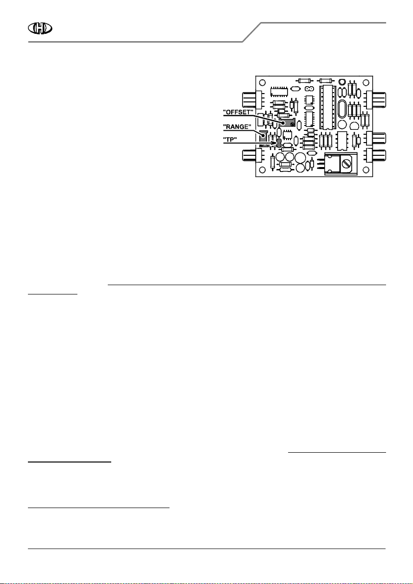
Figure 2.9.1
Figure 2.9.1Figure 2.9.1
Figure 2.9.1
There are two variable resistors on the interface board
labeled “OFFSET” and “RANGE” (fig. 2.9.1). They must be
adjusted before the interface is used. Adjustment
procedure is following
2
22
2
:
a) Leave the instrument open so there is an access for the
variable resistors adjustment with a small screwdriver.
b) Connect MIDI output of your MIDI master keyboard (or
PC / sequencer / DAW) to MIDI input of the interface
3
33
3
.
c) Connect audio output of the instrument to a tuner or to
a frequency meter.
d) Set all controllers on the instrument’s panel to a clear sound without any modulation:
• VCO I. Æ PITCH = 0, OCTAVE = 8’, MODE = Saw
• MIXER Æ knob fully counterclockwise, switch to VCO I.
• PORTAMENTO Æ switch to middle position (off)
• VCF Æ LOW PASS = 10, HIGH PASS = 0, EXPAND L.P = OFF, EXPAND H.P = OFF, BRIGHT = OFF, LFO = OFF
• ENVELOPE GENERATOR Æ ATTACK = 0, SINGING = 8, RANGE = x1, MODE = SUSTAIN, TRIGGER = KEY
• VCO MODULATOR Æ BEND switch to middle position (off), VIBRATO switch to middle position (off)
Positions of other controllers on instrument’s panel are not significant.
e) Plug instrument's power supply cable to a mains socket and switch the instrument on by main switch joined
with the VOLUME knob. Attention
Attention Attention
Attention -
--
- work very carefully during whole adjustment procedure
work very carefully during whole adjustment procedure work very carefully during whole adjustment procedure
work very carefully during whole adjustment procedure -
--
- there is a risk of
there is a risk of there is a risk of
there is a risk of
electric shock!
electric shock!electric shock!
electric shock!
f) Now, the interface is in "Stand-by" mode - the interface’s indication LED is off. If not, press the "RESET"
button of the interface.
g) Wait a few minutes
Wait a few minutesWait a few minutes
Wait a few minutes to stabilize the temperature of all instrument circuits.
h) Measure the voltage between pins of the "TP" jumper head (fig. 2.9.1) with a quality digital multimeter. It
should be zero volts exactly. If it is not, adjust it with "OFFSET” variable resistor on the interface board (fig.
2.9.1).
i) Press the highest key on the instrument’s keyboard (i.e. C4) - indication bi-color LED remains off.
j) Measure the output tone frequency by the tuner (frequency meter). It should be 2093 Hz approx. Remember
the measured tone frequency. Then release the C4 key.
k) Press the C4 key on the master keyboard (i.e. send MIDI Note Nr. 96 to the interface) and hold it. The
indication LED will light in green.
l) Check the output tone frequency by the tuner (frequency meter) again. It must be the same as the frequency
measured in paragraph j). If it is not, adjust it with "RANGE” variable resistor on the interface board (fig. 2.9.1).
m) Release the C4 key on the master keyboard. Switch the instrument off and disconnect the power supply
disconnect the power supply disconnect the power supply
disconnect the power supply
cable from mains socket
cable from mains socketcable from mains socket
cable from mains socket.
2
It is suppossed that the interface is in "Factory Reset" status before the adjustment procedure. If it is not, send the F0 00 20 21 7F 54 50 03 7F 5A
F0 00 20 21 7F 54 50 03 7F 5A F0 00 20 21 7F 54 50 03 7F 5A
F0 00 20 21 7F 54 50 03 7F 5A
F7 [hex]
F7 [hex]F7 [hex]
F7 [hex] SysEx message to the intarface first.
3
Set transmit MIDI Channel to number 1 on the master keyboard.


