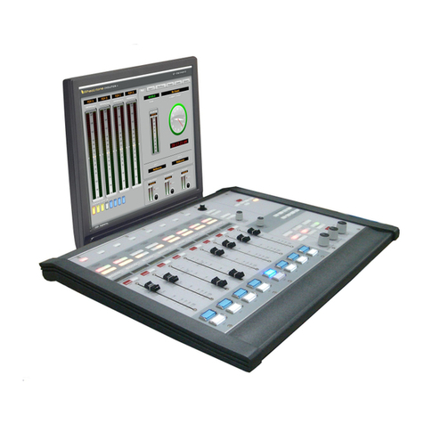
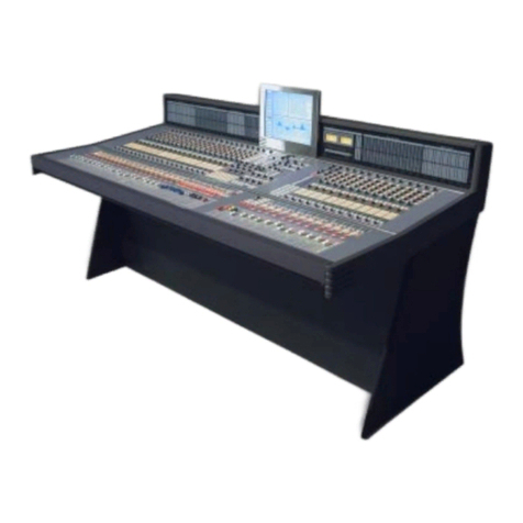
Wheatstone Corporation Dimension Three User manual

Dimension THREE
600 Industrial Drive, New Bern, North Carolina, USA 28562
Television Digital Control Surface
TECHNICAL MANUAL

WHEATSTONE CORPORATION
600 Industrial Drive
New Bern, North Carolina 28562
tel 252-638-7000 / fax 252-637-1285
DIMENSION THREE Television Digital Control Surface Technical Manual
©2015 Wheatstone Corporation
DIM THREE / July 2015

Attention
ReAd Me!
July 2015
Attention!
Federal Communications Commission (FCC) Compliance
Notice:
Radio Frequency Notice
NOTE: This equipment has been tested and found to comply with the
limits for a Class A digital device, pursuant to Part 15 of the FCC rules. These
limits are designed to provide reasonable protection against harmful inter-
ference when the equipment is operated in a commercial environment. This
equipment generates, uses, and can radiate radio frequency energy and, if
not installed and used in accordance with the instruction manual, may cause
harmful interference to radio communications. Operation of this equipment
in a residential area is likely to cause harmful interference in which case the
user will be required to correct the interference at his own expense.
This is a Class A product. In a domestic environment,
this product may cause radio interference, in which case,
the user may be required to take appropriate measures.
This equipment must be installed and wired properly in order to assure
compliance with FCC regulations.
Caution!
Any modications not expressly approved in writing by
Wheatstone could void the user's authority to operate this equipment.

Read Me!
July 2015
IMPORTANT!
Cleaning the Acrylic Surface
An acrylic surface is a beautiful, lustrous material that is outstanding in
durability and break resistance. With proper care, it will retain its attractive
appearance for many years to come. This care should include precautions against
scratching or contact with objects of high temperature that might mar the surface.
A few simple precautions will preserve the beauty of the acrylic.
• FIRST be sure the surface to be cleaned is powered off.
• NEVER spray or pour any liquid directly onto the surface.
• TO AVOID scratching these surfaces, use a soft brush or cloth to gently
brush away any larger dirt particles.Alternately the larger particles can be blown
from the surface with the use of canned air.
• USE a soft, clean lint free cloth or micro ber cloth and clean lukewarm
water to clean the surface. For stubborn dirt and stains use a mild, nonabrasive
soap and water mixture with the gentle cleaning cloth. Use only light pressure
when cleaning. Avoid rubbing dirt or grit into the surface. Turn the cloth often
and replace with a clean cloth frequently. Dry by blotting gently with a clean,
dry cloth.
• AVOID using kleenex, paper towels, sponges or other coarse shop towels,
as these materials may contain abrasives that can scratch acrylic surface.
• DO NOT USE ketones, aromatics, esters, halogens, window cleaning sprays,
alcohol, kitchen scouring compounds, or solvents (such as acetone, benzene,
gasoline, carbon tetrachloride, or thinners).
Caution! Do not use ammonia based cleaning solutions as they can cause
the surface to yellow, and became brittle and eventually cause structural damage
to the acrylic surface.
Wheatstone will not be liable for damage resulting from improper cleaning
and maintenance.

page Contents – 1
DIM THREE / July 2015
CONTENTS
Technical Manual
Table of Contents
Introduction....................................................................................1-2
Control Surface Placement...........................................................1-3
Power Supply.................................................................................1-4
Failsafe Dual Redundant Supply ................................................................................1-5
Energizing...................................................................................................................1-5
I/O Connections.............................................................................1-6
Dimension Three
Meterbridge LCD Screens at a Glance ...........1-7
Controls and Functions ................................................................2-2
Input Sources .............................................................................................................2-3
GAIN Control ..............................................................................................................2-3
Phantom Power..........................................................................................................2-3
SOFT ..........................................................................................................................2-3
Mapping SOFT Functions .....................................................................................2-4
Mode Selector Indicator.............................................................................................2-4
Pan/Balance Knob .....................................................................................................2-4
Bus Minus (BUS -) / Direct Output..............................................................................2-5
Main Bus Assign.........................................................................................................2-5
Dynamics and EQ.......................................................................................................2-5
MXM/SUB Indicators..................................................................................................2-5
AFV Button - Audio Follow Video...............................................................................2-6
AUTOMIX Button........................................................................................................2-6
Auto-Mix Overview................................................................................................2-6
Operation...............................................................................................................2-6
SPILL Button ..............................................................................................................2-6
Talkback .....................................................................................................................2-6
DCM (Digital Control Master) Indicators.....................................................................2-7
Source Display ...........................................................................................................2-7
Channel ON Switch ....................................................................................................2-7
SET Button .................................................................................................................2-7
PFL - Pre Fade Listen ................................................................................................2-7
AFL - After Fade Listen .............................................................................................2-7
Fader ..........................................................................................................................2-8
Chapter 1 - General Information
Chapter 2 - Input Panel (IS-D3)
Dimension Three

page Contents – 2
DIM THREE / July 2015
CONTENTS
Controls and Functions ................................................................3-3
Monitors .....................................................................................................................3-3
Control Room Section...........................................................................................3-4
Studio Section.......................................................................................................3-4
Speaker Muting .................................................................................................3-5
Headphone Section...............................................................................................3-5
Mode Control and Indicators ................................................................................3-6
Bus Assign Section ....................................................................................................3-6
Surround/PAN System ...............................................................................................3-7
Mode Select Section ..................................................................................................3-8
MUTE/DIM/PFL/AFL Section .....................................................................................3-8
Clear PFL....................................................................................................................3-9
AUX/MXM Masters Outputs.......................................................................................3-9
Mix-Minus Assign......................................................................................................3-10
DCM Assign ..............................................................................................................3-10
Switched Meters Section ..........................................................................................3-10
Copy Section.............................................................................................................3-10
Copy Multiples .....................................................................................................3-11
To Copy One and Paste Many .............................................................................3-11
To Copy One To All...............................................................................................3-11
Test Tones Oscillator .................................................................................................3-12
Controls................................................................................................................3-12
Routing Test Tones ...............................................................................................3-12
System Router Section .............................................................................................3-12
Selecting Input Channel Sources.........................................................................3-12
Selecting Output Mix Destinations.......................................................................3-13
Changing Output Mix Destinations ......................................................................3-13
Removing Output Mix Destinations .....................................................................3-13
X-Y SET Button ....................................................................................................3-13
Event Controller Section............................................................................................3-14
Storing an Event...................................................................................................3-14
Taking an Event ....................................................................................................3-14
Undoing an Event.................................................................................................3-14
Modifying the Currently Selected Event...............................................................3-14
Deleting an Event .................................................................................................3-14
Previewing an Event .............................................................................................3-15
Event Default Button ............................................................................................3-15
Establishing the Default Setting ...........................................................................3-15
Naming an Event ..................................................................................................3-15
Control Modes......................................................................................................3-15
EQ Section ................................................................................................................3-17
High-Pass Filter....................................................................................................3-17
Low-Pass Filter.....................................................................................................3-17
Equalizer...............................................................................................................3-18
Phase....................................................................................................................3-18
Chapter 3 - Control Panel (EFS-D3)

page Contents – 3
DIM THREE / July 2015
CONTENTS
Controls and Functions ................................................................4-2
Master Program Outputs............................................................................................4-2
Mix Destination 5.1 Surround................................................................................4-2
Master Mix Routing ...............................................................................................4-3
Channel Master ON/OFF.......................................................................................4-3
EQ..........................................................................................................................4-3
GATE......................................................................................................................4-4
COMP....................................................................................................................4-4
DCM Master Displays............................................................................................4-4
PFL - Pre Fade Listen............................................................................................4-4
Master Faders .......................................................................................................4-4
Submixes Output .......................................................................................................4-5
Output Destinations, Submix 1 Example ..............................................................4-5
Submixes Output Display......................................................................................4-5
SUB Button ...........................................................................................................4-5
EQ..........................................................................................................................4-6
GATE......................................................................................................................4-6
COMP....................................................................................................................4-6
DCM Submix Displays ..........................................................................................4-7
ON Switch .............................................................................................................4-7
PFL - Pre Fade Listen............................................................................................4-7
Submix Faders ......................................................................................................4-7
Controls and Functions ................................................................5-3
Audio Delay ................................................................................................................5-3
Gate............................................................................................................................5-4
Threshold...............................................................................................................5-4
Open and Close ....................................................................................................5-4
Depth.....................................................................................................................5-4
Compressor/Limiter....................................................................................................5-4
Threshold...............................................................................................................5-5
Attack ....................................................................................................................5-5
Ratio ......................................................................................................................5-5
Release..................................................................................................................5-5
Makeup Gain .........................................................................................................5-5
AUX Sends .................................................................................................................5-6
MXM Condence Feed...............................................................................................5-7
Condence All and Remote Trigger Switches.......................................................5-7
Making It All Work .................................................................................................5-7
Routing Condence Feed Audio ...........................................................................5-7
Info Button..................................................................................................................5-8
Talkback Preselects....................................................................................................5-8
Display Buttons ..........................................................................................................5-9
Programmable Buttons .............................................................................................5-10
Layers........................................................................................................................5-10
Conguring Layers ...............................................................................................5-10
Layer Setup Details ..............................................................................................5-11
Layer COPY - PASTE ...........................................................................................5-12
Layer Options .......................................................................................................5-12
Chapter 4 - Master Panel (MFS-D3)
Chapter 5 - Dynamic Processing Control Panel (DCM-D3)

page Contents – 4
DIM THREE / July 2015
CONTENTS
Audio Clip Player.......................................................................................................5-12
Open Clip Play Screen .........................................................................................5-12
Clip Player Control ...............................................................................................5-13
Track Start Control ...............................................................................................5-13
Sample Playlist File ..............................................................................................5-14
Page Subs Button .....................................................................................................5-14
MXM/Subs Button.....................................................................................................5-14
BS.1770-3 Loudness Monitor ...................................................................................5-14
The Multi-channel Loudness Algorithm................................................................5-14
Units and References ...........................................................................................5-15
Meter Components ..............................................................................................5-15
Audio Source...................................................................................................5-15
Bargraphs........................................................................................................5-16
Integrated Loudness .......................................................................................5-16
Gating..............................................................................................................5-16
Loudness Range .............................................................................................5-16
Program Duration Timer ..................................................................................5-16
Operation..............................................................................................................5-17
Logic Control........................................................................................................5-17
Using External Control ....................................................................................5-17
Logging ................................................................................................................5-17
Options Settings...................................................................................................5-18
Mute Groups .............................................................................................................5-18
Fader .........................................................................................................................5-18
Overview.........................................................................................6-2
HC-D2 BIOS Settings/Format .....................................................6-2
Ethernet IP Addressing .............................................................6-2
Ethernet Interface Wiring..............................................................6-2
Mixer Link Wiring...........................................................................6-3
Internal Programming Options.....................................................6-3
Switch Settings ..........................................................................................................6-3
SW1-SW4 - CAT5/CAT6 vs. Fiber & Transceiver Select........................................6-3
SW5 - Master Failover...........................................................................................6-3
SW6 - CPU Reset..................................................................................................6-3
SW7 Position 1 - Sample Rate..............................................................................6-3
SW7 Position 2 - Redundant CPU ........................................................................6-4
SW7 Position 3 - Not Used ...................................................................................6-4
SW7 Position 4 - CAT5/CAT6 vs. Fiber .................................................................6-4
Hook-Ups........................................................................................6-4
“ETH A” RJ-45 - Main Ethernet Connector................................................................6-4
“ETH B” RJ-45 - Optional Redundant Computer Ethernet Connector ......................6-4
“CAT5” RJ-45 - Mixer Link Connector .......................................................................6-4
Typical Straight-Through Cable ...................................................6-5
Typical Crossover Cable...............................................................6-5
All devices in the
system must be
set to the same
sample rate!
Chapter 6 - Host CPU (HC-D2)

page Contents – 5
DIM THREE / July 2015
CONTENTS
Optical Fiber Interface...................................................................6-6
Optical Transceiver.....................................................................................................6-6
Connector Types ........................................................................................................6-6
Optical Fiber Cable.....................................................................................................6-6
HC-D2 Pinouts Drawing ................................................................6-7
Options Text File ...........................................................................A-3
Introduction ................................................................................................................A-3
Modifying The Options Text File.................................................................................A-3
A Simple Example From The File ...............................................................................A-4
A Second Example.....................................................................................................A-5
An Example File - Complete.......................................................................................A-6
Replacement Parts List................................................................A-11
Appendices
Appendix 1
Appendix 2

page 1 – 1
DIM THREE / July 2015
GENERAL INFORMATION
Chapter Contents
General Information
Introduction....................................................................................1-2
Control Surface Placement...........................................................1-3
Power Supply.................................................................................1-4
Failsafe Dual Redundant Supply ................................................................................1-5
Energizing...................................................................................................................1-5
I/O Connections.............................................................................1-6
Dimension Three
Meterbridge LCD Screens at a Glance ...........1-7

page 1 – 2
DIM THREE / July 2015
GENERAL INFORMATION
General Information
Introduction
Wheatstone’s Dimension Three Digital Television Audio Control Surface is exactly the
control surface you need to make your show a success – day in and day out. Dimension Three
is the rst large‑format audio control surface that is so truly universal it can t into almost
any TV production environment, anywhere – whether it’s a Wheatstone TDM routed studio,
a MADI‑equipped stadium, a remote truck, or even the newest space in studio networking
based on IP connectivity. You will never run out of console with Dimension Three’s 16 true
submixes, each of each can be mono, stereo, or 5.1 surround. There are 16 stereo AUX sends
and 16 dedicated mix‑minus busses, plus a Bus‑Minus (N‑1) / Direct output for every input
channel (up to 128 in all). That’s on top of the two stereo and two 5.1 surround master busses.
The surface is layered, so that each physical fader controls 8 sources, each of which can
be mono, stereo, or full 5.1. Each fader also has a “spill” function, which allows its individual
channels to spill out onto two faders for stereo and six separate faders for 5.1 sources. The
control surface employs motorized faders that are recalled with Event snapshots. Each fader’s
alpha‑numeric LED display always indicate a fader’s current source to eliminate operator
confusion. Two programmable soft knobs per input – can be assigned any control functions
on the control surface. The Dimension Three gives your operators the added convenience of
four DCM/MUTE busses, and 100 Event memory locations accessed via a front panel storage
and recall system that doesn’t require an external computer to operate. Dimension Three
features Automatic microphone mixing ( AutoMix), which automatically optimizes the levels
of several microphones during dialogue, and Audio‑Follow‑Video (AFV), which allows the
control surface to automatically control input channels based on the video source currently
being taken. Up to 20 frames of Delay are available on any input or output fader. The control
surface incorporates programmable controls for talkback and miscellaneous routing and
switching functions. Digital audio processing is available on every input channel and on all
major output busses (EQ, compressor/limiter, gate, high/low pass lters).
Once congured, the system operates entirely independently of external computers.
Conguration is intuitive and carried out onsite by means of user‑friendly graphic interfaces
provided by Wheatstone XPoint router control software. The Dimension Three system also
takes full advantage of Wheatstone’s exclusive VDip conguration software, so that studio
functions (like mutes, fader and timer starts, tally, etc.) are easily accomplished right at your
desktop. Once completed, all settings are retained in non‑volatile storage, allowing the entire
system to run independently. Wheatstone’s ACI Automation Control Interface protocol is
built in, providing a streamlined interface with video switchers, automation, scheduling, and
hardware controllers as you require.

page 1 – 3
DIM THREE / July 2015
GENERAL INFORMATION
Control Surface Placement
The Dimension Three digital audio control surface is designed for countertop
mounting.Although the rubber feet on the bottom keep the surface from being easily
moved when simply placed on the counter, holes have been provided so that screws
may be used to mount the surface securely to the countertop. Carefully remove the
appropriate panels from the frame, screw the mainframe to the counter top, and
reinstall the removed panels. The three most common frame sizes dimensions are
shown in the drawings below. Larger frame sizes are available as well.
Do not connect the Dimension Three control surface to its power supply (and
do not connect the power supply to theAC power line) until instructed to do so.
27-1/4"
59-1/2"
14-1/2"
USE #8 SCREWS
8 HOLES, D=
3/16";
25-1/16" 17-11/16"
27-1/4"
11-7/8"
2-1/4"
DIMENSION THREE - 24 INPUTS FRAME
27-1/4"
72"
DIMENSION THREE - 32 INPUTS FRAME
18-3/4" 18-3/4" 17-11/16"12-1/8"
USE #8 SCREWS
10 HOLES, D=
3/16";
14-1/2"
27-1/4"
47"
24-5/8" 17-11/16"
DIMENSION THREE - 16 INPUTS FRAME
14-1/2"
USE #8 SCREWS
6 HOLES, D=
3/16";
2-3/16"
2-3/16"
2-3/16"
12-1/8"

page 1 – 4
DIM THREE / July 2015
GENERAL INFORMATION
If failsafe redundant sup-
plies have been ordered,
you will be installing two
SPS-400 units.
Power Supply
Power Supply
End
Control Surface
End
8
7
6
5
PIN
1
2
3
4
PIN
8-pin Connector
Male
5-pin Connector
Female
Power Supply EndConsole End
4
3
2
1
5
RED, YEL
BLU, BLK
N/C
N/C
N/C
N/C
N/C
N/C
PS Cable Pinou
t
RED
YEL
BLU
BLK
N/C
+V in
-V in
Front view of the PSR rackmount power supply
Rear view of the PSR with two SPS-400 units
Once the supply is rack‑mounted,
it should be connected to the control
surface using the factory supplied
cable. The cable has two different
types of connectors on it: a 5‑pin
female connector that connects to
the control surface’s power supply
connector, and an 8‑pin male
connector that plugs into the PSR
power supply. The control surface’s
two power supply connectors are
located at the rear of the control
surface, in the middle of the meter‑
bridge bottom pan. If you are using
one supply, connect it to one of the
control surface connectors (it doesn’t
matter which one). If you are using the
failsafe option, connect one end of a
power supply cable to either control
surface power connector and connect
the other end of the cable to one of
the two power supply connectors.
Then use the other cable to connect
the second power supply connector
to the remaining control surface power supply connector. Connect the cable(s) rst to the
control surface, then to the rear of the rackmount power supply.
The Dimension Three control surface is powered by an SPS‑400 power
supply installed in a Wheatstone Model PSR rackmount unit. Each PSR
houses up to two SPS‑400 power supply units. Mount the power supply in
a standard 19” equipment rack, keeping in mind that adequate ventilation
is necessary to prevent heat build‑up within the rack.
Note the power supplies should be mounted in an equipment rack within
fteen feet of the control surface.

page 1 – 5
DIM THREE / July 2015
GENERAL INFORMATION
Note each power supply is tted with a 3‑wire grounded AC cord
that should be plugged into a “clean” AC power source, that is, an AC
source that feeds only the control room audio gear. This source should
be a separate feed from those powering lighting, air‑conditioning, or any
other non‑audio machinery. The third pin ground wire of the AC source
should be tied to the central system ground point.
Failsafe Dual Redundant Supply
Wheatstone failsafe power supply systems use two SPS‑400 power
supplies for each piece of powered equipment. Though either is capable
of running a full load on its own, in failsafe operation both units run in
tandem: if one fails, the other takes over, assuring uninterrupted operation.
In order for failsafe systems to perform as designed, always have BOTH
power supplies powered up and connected to their associated equipment.
Energizing
Assuming the Dimension Three control surface mainframe is properly
placed, and its PSR power supply (or supplies) correctly rackmounted
and connected to the control surface, you may now energize the PSR
rackmount power supply by plugging it into the AC mains. The control
surface’s LCD displays will illuminate and individual module switches
will assume factory default settings.
Note: To de‑energize the control surface, unplug the rackmount power
supply’s AC cord from the AC mains. Never de-energize the control
surface by disconnecting the cable that connects the control surface
and power supply together.
Once you have veried proper power-up, unplug the rackmount power
supplies to de-energize the control surface. You may now proceed to
wire up audio and control connections
The power feed rec-
ommended in the text
is often installed and
referred to in studios as
an “isolated AC ground”
outlet. It is usually orange
in color.

page 1 – 6
DIM THREE / July 2015
GENERAL INFORMATION
I/O Connections
All user wiring to and from the Dimension Three control surface is made via
connectors located on the control surface’s rear panel.
On the left rear of the frame a Main CPU’s connectors: a Serial Port DB‑9 connector
(not used), an Ethenet RJ‑45 connector, a Keyboard PS2 connector and a VGA DB‑15
connector for factory use only.
MIXER LINK CAT5/CAT6 or multi‑mode optical FIBER connections are made
via RJ‑45 or LC type optical connectors. Two 5‑pin male connectors are for power
supply connections.
The photo below shows connector locations.
There is also a dual USB connector labeled AUDIO and
USER located in the right hand end of the meterbridge facing
the operator. The AUDIO port is for USB thumb drive containing
audio WAV les and M3U playlists les. The USER port provides
le and conguration access for future conguration software.
For all wiring pinout connections refer to Chapter 6.
NOTE: Keyboard
and VGA connectors
for factory use only.
POWER B
POWER A
MIXER LINK
CAT **
FIBER
SERIAL PORT
Not Used
ETHERNET
COMPACT
FLASH DRIVE
VGA*
MAIN CPU
BACKUP
CPU
KEYBOARD
*
1366x768 VGA default resolution. Plugging
in monitors with other resolutions will cause
surface screens to draw incorrectly.
**
IMPORTANT!
CAT5/CAT6 cables
crossover wired.

DIM THREE / July 2015
The MINI FLIP button on the DCM‑D3 panel toggles the lower portion of the input channels LCD display
to show EQ and dynamics curves instead of default submix and aux assigns.
Press LAYER SETUP on the DCM‑D3 to enter layer SETUPmode.
page 1 – 7
Dimension Three Meterbridge LCD Screens at a Glance
Loudness Monitor Screen
Tapping the SOURCE
knob at the top of the IS‑D3
panel opens a pop‑up Input
Sources List.
Tapping the SOURCE
knob at the top of the IS‑D3
panel at the Layer SETUP
mode opens a pop‑up
Layer Channel Select List.
Input Panel LCD Screen

DIM THREE / July 2015
Pressing the SET button on an input channel opens up detail view screen for any fader
on the control surface.
MXM/AUX button located on the DISPLAYsection
of the DCM‑D3 panel toggles the standard LCD
display to show metering for the 16 stereo AUX
send outputs or the 16 Mix‑Minus outputs.
CONF ZOOM button located on the DISPLAY
sectionoftheDCM‑D3panelzoomsthecondence
feed portion of the LCD display to double size.
CLIP PLAYbutton located on the DISPLAY section of
the DCM‑D3 panel switches the player into the lower
right corner of the Master LCD screen.
Pressing the INFO button on the DCM‑D3 panel will
bring up into the lower right corner of the Master LCD
screen the System Information window with techni‑
cal information about the surface’s software version
and connection status to its companion rack MT link,
Ethernet link, and automation interface.
page 1 – 8
Dimension Three Meterbridge LCD Screens at a Glance
Master Panel LCD Screen

page 2 – 1
DIM THREE / July 2015
INPUT PANEL
Input Panel (IS-D3)
Controls and Functions ................................................................2-2
Input Sources .............................................................................................................2-3
GAIN Control ..............................................................................................................2-3
Phantom Power..........................................................................................................2-3
SOFT ..........................................................................................................................2-3
Mapping SOFT Functions .....................................................................................2-4
Mode Selector Indicator.............................................................................................2-4
Pan/Balance Knob .....................................................................................................2-4
Bus Minus (BUS -) / Direct Output..............................................................................2-5
Main Bus Assign.........................................................................................................2-5
Dynamics and EQ.......................................................................................................2-5
MXM/SUB Indicators..................................................................................................2-5
AFV Button - Audio Follow Video...............................................................................2-6
AUTOMIX Button........................................................................................................2-6
Auto-Mix Overview................................................................................................2-6
Operation...............................................................................................................2-6
SPILL Button ..............................................................................................................2-6
Talkback .....................................................................................................................2-6
DCM (Digital Control Master) Indicators.....................................................................2-7
Source Display ...........................................................................................................2-7
Channel ON Switch ....................................................................................................2-7
SET Button .................................................................................................................2-7
PFL - Pre Fade Listen ................................................................................................2-7
AFL - After Fade Listen .............................................................................................2-7
Fader ..........................................................................................................................2-8
Chapter Contents

page 2 – 2
DIM THREE / July 2015
INPUT PANEL
Input Panel (IS-D3)
Source (X) Controllers
Controls and Functions
Each input panel of the Dimension Three digital
audio control surface has four identical strips.
A dedicated LCD monitor for every eight input faders
displays the currently selected DSP channel number,
Preset sources, Source and Gain reduction metering,
Automix status, Submix and Aux assignments, and
Programmable controller values.
The MINI FLIP button on the
DCM‑D3 panel toggles the lower
portion of the input channels
LCD display to show EQ and dy‑
namics curves instead of default
submix and aux assigns.
Pressing the SET button on an input channel opens up
detail view screen for any fader on the control surface.

page 2 – 3
DIM THREE / July 2015
INPUT PANEL
Input Sources
Dimension Three is a router based system so any input fader may
access any source wired to the Wheatstone router.
The D3Visibility setting in XPoint software limits
what the user “sees” when they scroll through the
signal list.
Select a Source for the Input fader by dobbying
the SOURCE knob. A pop‑up list displays all
available source signals. Scroll the list until the
desired source is highlighted. Signals may be
grouped into folders (MICS, TechCore, etc.) by lling in the Location
eld for each signal name in XPoint software.
Sources may be mapped into the PRESET1 or PRESET2 button.
Scroll the SOURCE knob until the desired source appears in the
SOURCE window, then press and hold the PRESET1 or PRESET2
button until the switch’s LED lights. Once loaded, this source can be
connected at any time by pressing the PRESET1 or PRESET2 button.
NOTE: Gain settings are NOT saved
with Events. This is to prevent accidental
changes in multi surface systems.
Phantom Power
The PHANT on/off switch applies phantom voltage to any selected
microphone. The phantom power attribute stays on even when the
microphone is not selected on the control surface.
SOFT
Each Input channel strip has two SOFT encoders/
switches. Each bank of these “soft” controls may be
mapped to control almost any input channel parameter
located in the central control section. For instance, you
could map the top bank of SOFT controls to be Aux
Send 1. Then map the lower bank to be DELAY.
SOFT Encoder – The SOFT encoder’s behavior
will change depending on which function is mapped
TIP:
DOBBY (pronounce dah-
bee) - means to quickly
press and release an en-
coder knob.
GAIN Control
The GAIN level control allows gain of an incoming source to
be trimmed. The relative gain setting can be read from the input
fader’s LCD screen or from the selected channel’s detail screen
if the channel’s SET button is pressed.
Table of contents
Other Wheatstone Corporation Recording Equipment manuals

Wheatstone Corporation
Wheatstone Corporation A-2000 User manual

Wheatstone Corporation
Wheatstone Corporation A-5000 User manual

Wheatstone Corporation
Wheatstone Corporation A-7000 User manual

Wheatstone Corporation
Wheatstone Corporation TV-1000 User manual

Wheatstone Corporation
Wheatstone Corporation D-5.1 User manual

Wheatstone Corporation
Wheatstone Corporation E-6 User manual

Wheatstone Corporation
Wheatstone Corporation DMX-8 User manual

Wheatstone Corporation
Wheatstone Corporation E-4 User manual

Wheatstone Corporation
Wheatstone Corporation EMX User manual

Wheatstone Corporation
Wheatstone Corporation A-32 User manual